Burkert 8644 AirLINE Operating Instructions Manual
Hide thumbs
Also See for 8644 AirLINE:
- Operating instructions manual (224 pages) ,
- Quick start manual (58 pages) ,
- Operating instructions manual (73 pages)

Related Manuals for Burkert 8644 AirLINE


Summary of Contents for Burkert 8644 AirLINE
- Page 1 Operating Instructions Bedienungsanleitung Instructions de service Type 8644 AirLINE with Point I/O System (Rockwell) mit Point I/O System (Rockwell) avec Point I/O System (Rockwell)
- Page 2 We reserve the right to make technical changes without notice. Technische Änderungen vorbehalten. Sous resérve de modification techniques. © 2002 Bürkert Werke GmbH & Co. KG Operating Instructions 0605/06_EU-EN_00804718...
- Page 3 Add-on dimension 11 mm...
- Page 4 Add-on dimension 16,5 mm...
-
Page 5: Table Of Contents
ONTENTS List of contents Type 8644 AirLINE -Rockwell GENERAL NOTES ..............................................Symbols ..................................................General safety notes ..........................................Scope of delivery ............................................Warranty conditions ............................................ Approvals ................................................. Assembly note ..............................................Information of the Internet ........................................INSTALLATION/COMMISSINONING ..................................Installation instructions ........................................... Illustration of the Valve block ...................................... - Page 6 ONTENTS SYSTEM DESCRIPTION ......................................... Bürkert-AirLINE modulare elektrical / pneumatic automation system ..............Valve block (variable configuration) ................................... Valve units ................................................Connector modules ..........................................Basic electrical module ........................................Basic pneumatic module ........................................Valves ..................................................Limitations for use in Zone 2 ......................................ANNEX ....................................................
-
Page 7: General Notes
ENERAL OTES General Notes SYMBOLS ..................................................GENERAL SAFETY NOTES ......................................Protection from damage by electrostatic charging ............................Safety notes for the valve ..........................................SCOPE OF DELIVERY ..........................................WARRANTY CONDITIONS ......................................... APPROVALS ................................................ASSEMBLY NOTE .............................................. INFORMATION ON THE INTERNET ..................................8644/Rockwell - 3... -
Page 8: Symbols
ENERAL OTES SYMBOLS The following symbols are used in these operating instructions: marks a work step that you must carry out ATTENTION! marks notes on whose non-observance your health or the functioning of the device will be endangered NOTE marks important additional information, tips and recommendations GENERAL SAFETY NOTES Please observe the notes in these operating instructions together with the conditions of use and permitted data that are specified in the data sheet, in order that the device will function perfectly and remain operab-... - Page 9 ENERAL OTES Safety notes for the valve ATTENTION! • Keep to standard engineering rules in planning the use of and operating the device! • Take suitable precautions to prevent inadvertent operation or damage by unauthorized action! • Note that in systems under pressure, piping and valves may not be loosened! 0 bar, psi, kPa •...
-
Page 10: Scope Of Delivery
ENERAL OTES SCOPE OF DELIVERY Immediately after receipt of the goods, make sure the contents are undamaged and agree with the scope of delivery stated on the packing slip. In case of irregularities, contact our customer service department at once: Bürkert Fluid Control Systems Service Department Chr.-Bürkert-Str. -
Page 11: Installation/Commissinoning
NSTALLATION OMMISSIONING Installation / Commissioning Installation instructions........................8 Illustration of the Valve block ......................8 Removing the valve block from the top-hat rail .................. 9 Installation of the AirLINE system ....................10 Fluidic installation ..........................11 Labelling of the connections ......................12 Electrical installation ........................ -
Page 12: Installation Instructions
NSTALLATION OMMISSIONING Installation instructions The valve block of the AirLINE-system Type 8644 is combined with the Point I/O System from the Rockwell company. Please observe the respective installation notes. ATTENTION! Before starting installation work, switch off the voltage in the vicinity and secure it against being switched on again. -
Page 13: Removing The Valve Block From The Top-Hat Rail
NSTALLATION OMMISSIONING Removing the valve block from the top-hat rail The valve block is firmly screwed to a standard rail. Additional electrical modules / terminals can be mounted on this. If present, release the adjacent modules / terminals! Unlock the Vavle block from the standard rail by turning the fixing screws anticlockwise as far as they will go. -
Page 14: Installation Of The Airline System
NSTALLATION OMMISSIONING Installation of the AirLINE system (e.g. in a control cabinet) ATTENTION! During work in the control cabinet, observe the relevant safety regulations! Before mounting, check whether the mounting rail is properly anchored in the control cabinet or in the system. Observe the sequence of installation specified in the configuration file(s). -
Page 15: Fluidic Installation
NSTALLATION OMMISSIONING Fluidic installation Safety notes ATTENTION! The pneumatic connections shall not be pressurized during installation! Make the connections with as large a volume as possible. Close off unused, open ports with screw caps! The ports for the pilot valve exhaust (x) shall not be closed off! Check allocation according to instructions of ports 1 and 3 or 5: these shall under no circumstances be swapped! Pneumatic connections - supply units... -
Page 16: Labelling Of The Connections
NSTALLATION OMMISSIONING Pneumatic connections - valve units NOTE With 3/2-way valves, the upper ports remain free! Labelling area Service ports with 5/2- way valves Service ports with 3/2- way valves 8-fold valve unit or 4 / 2-fold valve units Variants 5/2-way valves Variant 1 Variant 2... -
Page 17: Elektrical Installation
NSTALLATION OMMISSIONING Elektrical installation All the necessary steps for this should be taken from the Rockwell Operating Instructions Chapter 2 „Wiring the Adapter“. Fluidic commissioning Measures to be taken before fluidic initialization Check the connections, voltage and operating pressure! Make sure that the max. operating data (see rating plate) are not exceeded! Check allocation according to instructions of ports 1 and 3 or 5: these shall under no circumstances be swapped! For electrical operation, unlock the manual override! - Page 18 NSTALLATION OMMISSIONING Special features of commissioning On delivery, all valve islands possess a comparable configuration with regard to module addressing. The first addressable module after the field bus node has the address 62, all following modules the address 63. Reason: If a passive DeviceNet node (1734-PDN) is used, then automatic addressing can only be performed via the modules directly.
-
Page 19: Maintenance And Troubleshooting
AINTENANCE AND ROUBLESHOOTING Maintenance troubleshooting TROUBLESHOOTING ..........................................8644/Rockwell - 15... -
Page 20: Troubleshooting
AINTENANCE AND ROUBLESHOOTING TROUBLESHOOTING Fault Possible cause Remedy Valves do not switch: Operating voltage not present or insufficient; Check the electrical connection. Provide operating voltage acc. to nameplate. Manual override knob not in neutral position; Turn knob to zero position. Pressure supply insufficient or not present. -
Page 21: System Description
YSTEM ESCRIPTION System description MODULAR ELECTRICAL / PNEUMATIC AUTOMATION SYSTEM TYPE 8644 AIRLINE ............................ Features ....................................................Advantage .................................................... System structure ................................................. VALVE BLOCK ............................................... Connector modules / feeders ........................................Valve units .................................................... Technical data for the valve block ......................................Technical data for the overall system .................................... - Page 22 YSTEM ESCRIPTION Basic electronic module ME 02 / 8-fold 2 x monostable .......................... Basic electronic module ME03 / 2-fold monostable ............................Basic electronic module ME03 / 4-fold monostable ............................Basic electronic module ME03 / 3-fold 10 mm monostable ........................Basic electronic module ME03 / 2-fold bistable ..............................
-
Page 23: System Description
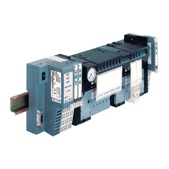
ESCRIPTION MODULAR ELECTIRCAL / PENUMATIC AUTOMATION SYSTEM TYPE 8644 AirLINE AirLINE Type 8644 is an electrical and pneumatic automation system which has been developed for use in control cabinets or boxes. In a through system, all electronic and pneumatic components are standardized so that if simple rules are complied with, electrical and electronic modules of differing functionality may be combined in a very simple manner. - Page 24 YSTEM ESCRIPTION System structure Schematic representation of the Bürkert AirLine system Illustration of the valve block Connector module left Manometer for indication of operating pressure at the station 8-fold valve unit Intermediate supply 2-fold valve unit Connector module right Supply and exhaust ports Service ports Supply and exhaust ports...
- Page 25 YSTEM ESCRIPTION System description In its minimal configuration, the system consists of field bus nodes and the valve block. The closing plate protects both the system and persons from improper contact. Terminals can be arranged before and after the valve block. Procedure for changing the electrical function module: ACHTUNG! Do not introduce foreign parts into the basic module (24V supply bus)-...
- Page 26 YSTEM ESCRIPTION VALVE BLOCK The valve block is composed of the following modules: • Connector modules/supply units (collective ports for supply, exhaust and auxiliary control air) • Valve units (service ports, miscellaneous vales) 8-fold valve Intermediate units supply Connector Connector module left module right Example of a valve block, schematic...
-
Page 27: Valve Units
YSTEM ESCRIPTION VALVE UNITS Construction Valve units are of modular construction and consist of: • Basic electronic modules • Basic pneumatic modules • Valves Valves Basic electronic module Service ports Basic pneumatic module (outputs) Modular construction of the valve units The digital outputs, on which the valves sit, are switched on the basic electronic module. - Page 28 YSTEM ESCRIPTION Technical data of the valve block ATTENTION! Observe current consumption of the modules! On project planning of an AirLINE station, observe the current consumption of the logic of each participant! This is given in each module-specific data sheet. It may differ from module to module.
- Page 29 YSTEM ESCRIPTION Technical data for the overall system Voltage supply: Rated voltage 24 V/DC Tolerance - 15% / + 20% Valve types 0460, 0461 - 10% / + 10% Valve type 6524 (2x 3/2-way) - 15% / + 10% Current carrying capacity: Logic area 24 V area 2.5 A...
-
Page 30: Connector Modules
YSTEM ESCRIPTION CONNECTOR MODULES Structure of the connector module (10) 8 + 9 Structure of the connector module Designation Description pneumatic supply Type MP11 / MP12 (left, middle, right) electrical connector Type ME02 / ME 03 (left, right) module Interface to electrical part of automation system (field bus nodes;... - Page 31 YSTEM ESCRIPTION Variants The supply units have been designed in various variants to take account of differing requirements. For simple commissioning and diagnosis, supply units are available with a manometer. You can obtain the fluidic connections with straight or conical screw connections as well as with fast coupling systems. For special functions the fluidic connections may be used for different purposes, e.g.
- Page 32 YSTEM ESCRIPTION Connector modules, pneumatic - left, type ME02 Variants Supply port (P) 1 Connection X Exhaust port (R/S) 3/5 without manometer G ¼ G ¼ D 10 D 10 NPT ¼ NPT ¼ with manometer G ¼ G ¼ D 10 D 10 NPT ¼...
- Page 33 YSTEM ESCRIPTION Technical data Housing dimensions (width x height x depth) 61 mm x 71 mm x 130 mm (incl. snap-on hooks) Weight 220 g Permissible temperature (storage/transport) -20 °C to +60 °C Permissible air humidity 75% mean, 85% occasionally ATTENTION! In the range of 0 to +55 °C, suitable precautions must be taken against elevated humidity (>...
- Page 34 YSTEM ESCRIPTION Conector modules, pneumatic - left, type ME03 Variants Supply port (P) 1 Connection X Exhaust port (R/S) 3/5 without manometer G 3/8 G 1/8 G 3/8 NPT 3/8 NPT 1/8 NPT 3/8 with manometer G 3/8 G 1/8 G 3/8 NPT 3/8 NPT1/8...
- Page 35 YSTEM ESCRIPTION Technical data Housing dimensions (width x height x depth) 78 mm x 93 mm x 143 mm (incl. snap-on hooks) Weight 400 g Permissible temperature (storage/transport) -20 °C to +60 °C Permissible air humidity 75% mean, 85% occasionally ATTENTION! In the range of 0 to +55 °C, suitable precautions must be taken against elevated humidity (>...
- Page 36 YSTEM ESCRIPTION Connector modules, pneumatic - middle, type ME02 Variants Supply port (P) 1 Connection X Exhaust port (R/S) 3/5 without manometer G ¼ G ¼ D 10 D 10 NPT ¼ NPT ¼ with manometer G ¼ G ¼ D 10 D 10 NPT ¼...
- Page 37 YSTEM ESCRIPTION Technical data Housing dimensions (width x height x depth) 52 mm x 71 mm x 119 mm (incl. snap-on hooks) Weight 118 g Permissible temperature (storage/transport) -20 °C to +60 °C Permissible air humidity 75% mean, 85% occasionally ATTENTION! In the range of 0 to +55 °C, suitable precautions must be taken against elevated humidity (>...
- Page 38 YSTEM ESCRIPTION Connector modules, pneumatic - middle, TYPE ME03 Variants Supply port (P) 1 Connection X Exhaust port (R/S) 3/5 without manometer G 3/8 G 1/8 G 3/8 NPT 3/8 NPT 1/8 NPT 3/8 with manometer G 3/8 G 1/8 G 3/8 NPT 3/8 NPT1/8...
- Page 39 YSTEM ESCRIPTION Technical data Housing dimensions (width x height x depth) 66 mm x 93 mm x 142 mm (incl. snap-on hooks) Weight 335 g Permissible temperature (storage/transport) -20 °C to +60 °C Permissible air humidity 75% mean, 85% occasionally ATTENTION! In the range of 0 to +55 °C, suitable precautions must be taken against elevated humidity (>...
- Page 40 YSTEM ESCRIPTION Connector modules, pneumatic - right, type ME02 Variants Supply port (P) 1 Connection X Exhaust port (R/S) 3/5 without manometer G ¼ G ¼ D 10 D 10 NPT ¼ NPT ¼ with manometer G ¼ G ¼ D 10 D 10 NPT ¼...
- Page 41 YSTEM ESCRIPTION Technical data Housing dimensions (width x height x depth) 61 mm x 71 mm x 130 mm Weight 220 g Permissible temperature (storage/transport) -20 °C to +60 °C Permissible air humidity 75% mean, 85% occasionally ATTENTION! In the range of 0 to +55 °C, suitable precautions must be taken against elevated humidity (>...
- Page 42 YSTEM ESCRIPTION Connector modules, pneumatic - right, type ME03 Variants Supply port (P) 1 Connection X Exhaust port (R/S) 3/5 without manometer G 3/8 G 1/8 G 3/8 NPT 3/8 NPT 1/8 NPT 3/8 with manometer G 3/8 G 1/8 G 3/8 NPT 3/8 NPT1/8...
- Page 43 YSTEM ESCRIPTION Technical data Housing dimensions (width x height x depth) 63 mm x 93 mm x 143 mm Weight 390 g Permissible temperature (storage/transport) -20 °C to +60 °C Permissible air humidity 75% mean, 85% occasionally ATTENTION! In the range of 0 to +55 °C, suitable precautions must be taken against elevated humidity (>...
- Page 44 YSTEM ESCRIPTION BASIC ELECTRONIC MODULES Functional module LED display General description The basic electronic module is connected to the adjacent modules via its electrical interface. In this Labelling area way it receives both voltage supply and control signals for the valves on the plug-on positions. The basic electronic modules and hences the valve units may be controlled as digital output modules/terminals.
-
Page 45: Basic Electronic Module Me 02 / 8-Fold 2 X Monostable
YSTEM ESCRIPTION Basic electronic module ME02 / 2-fold monostable Construction An electric base module consists of a distribution module (backplane bus) and a function module. The two modules are connected by a 14-pin board-to-board plug. Function display of LEDs Display of module status (only 1st valve position) Display of network status (only 2nd valve position) reed / green LED no function... -
Page 46: Basic Electronic Module Me03 / 2-Fold Monostable
YSTEM ESCRIPTION Basic electronic module ME02 / 8-fold monostable Construction A basic electronic module consists of a distributor module (back-wall bus) and a function module. Both modules are contacted via a 14-pole board-to-board connector. Function display of LEDs Module status (only 1st valve position) Network status (only 2nd valve position) red / green LED no function... - Page 47 YSTEM ESCRIPTION Basic electronic module ME02 / 2-fold bistable Construction A basic electronic module consists of a distributor module (back-wall bus) and a function module. Both modules are contacted via a 14-pole board-to-board connector. Function display of LEDs Module status (only 1st valve position) Network status (only 2nd valve position) red / green LED yellow LED...
- Page 48 YSTEM ESCRIPTION Basic electronic module ME02 / 2-fold 2 x monostable Construction An electric base module consists of a distribution module (backplane bus) and a function module. The two modules are connected by a 14-pin board-to-board plug. Function display of LEDs Display of module status (only 1st valve position) Display of network status (only 2nd valve position) red / green LED...
- Page 49 YSTEM ESCRIPTION Basic electronic module ME02 / 8-fold bistable Construction An electric base module consists of a distribution module (backplane bus) and a function module. The two modules are connected by a 14-pin board-to-board plug. Function display of LED Display of module status (only 1st valve position) Display of network status (only 2nd valve postion) red / green LED yellow LED...
- Page 50 YSTEM ESCRIPTION Basic electronic module ME02 / 8-fold 2x monostable Construction An electric base module consists of a distribution module (backplane bus) and a function module. The two modules are connected by a 14-pin board-to-board plug. Function display of LEDs Display of module status (only 1st valve position) Display of network status (only 2nd valve position) red / green LED...
-
Page 51: Basic Electronic Module Me03 / 4-Fold Monostable
YSTEM ESCRIPTION Basic electronic module ME03 / 2-fold monostable Construction A basic electronic module consists of a distributor module (back-wall bus) and a function module. Both modules are contacted via a 14-pole board-to-board connector. Function display of LEDs Module status (only 1st valve position) Network status (only 2nd valve position) red / green LED no function... - Page 52 YSTEM ESCRIPTION Basic electronic module ME03 / 4-fold monostable Construction A basic electronic module consists of a distributor module (back-wall bus) and a function module. Both modules are contacted via a 14-pole board-to-board connector. Function display of LEDs Module status (only 1st valve position) Network status (only 2nd valve position) red / green LED no function...
-
Page 53: Basic Electronic Module Me03 / 3-Fold 10 Mm Monostable
YSTEM ESCRIPTION Basic electronic module ME03 / 3-fold 10 mm monostable Construction A basic electronic module consists of a distributor module (back-wall bus) and a function module. Both modules are contacted via a 14-pole board-to-board connector. Function display of LEDs Module status (only 1st valve position) Network status (only 2nd valve position) red / green LED... -
Page 54: Basic Electronic Module Me03 / 2-Fold Bistable
YSTEM ESCRIPTION Basic electronic module ME03 / 2-fold bistable Construction A basic electronic module consists of a distributor module (back-wall bus) and a function module. Both modules are contacted via a 14-pole board-to-board connector. Function display of LEDs Module status (only 1st valve position) Network status (only 2nd valve position) red / green LED yellow LED... -
Page 55: Basic Pneumatic Module
YSTEM ESCRIPTION BASIC PNEUMATIC MODULE General description On the basic pneumatic module are to be found the service ports for subsequent applications. Several basic modules may be built up in a row by interlocking. Sealing from the outside is maintained. By unsing a bulkhead fitting, the P port may be sealed. -
Page 56: Basic Pneumatic Module With Integral Pressure Shut-Off
YSTEM ESCRIPTION Basic pneumatic module with integral pressure shut-off General description For the basic pneumatic module MP 11 in the 2-way and 8-way versions, an integral pressure shut-off is available as an option. With this option, a faulty valve may be exchanged under pressure without relieving the pressure in the entire valve island or system. -
Page 57: Valves
YSTEM ESCRIPTION Valves Types 6524 (2 x 3/2-way) / 6524 / 6525 Type 0460 / 0461 Type 6526 / 6527 EEx approval II 3 G EEx nA II T4 for the Types 6524 / 6525 [Exception Type 6524 (2x 3/2-way)]. General description Automation systems are increasingly used in all areas where control duties are to be performed. - Page 58 YSTEM ESCRIPTION Variants With AirLINE Type 8644, valves with the following circuit functions may be integrated: Valves Circuit function Actuation Width Type 3/2-way C (NC) internal control air 6524 D (NO) C (NC) auxiliary control air D (NO) C-vaccum (NC) 2 x 2/3-way 2 x C (NC) internal control air...
-
Page 59: Limitations For Use In Zone 2
YSTEM ESCRIPTION Limitations for use in Zone 2 ATTENTION! For valve types 6526 and 6527, for use in Zone 2 with temperature class T4, the limitation ≥ ≥ ≥ ≥ ≥ 0.2 s must be strictly complied with under the following (valve switch-off time) T conditions: •... - Page 60 YSTEM ESCRIPTION NOTES 56 - 8644/Rockwell...
- Page 61 PPENDIX APPENDIX EC-Declaration of Conformity ......................................Certificate of Conformity ..........................................8644/Rockwell - A1...
- Page 62 PPENDIX EC DECLARATION OF CONFORMITY Bürkert Werke GmbH & Co. KG hereby declares as the manufacturer that these products comply with the requirements listed in the Guidelines of the Council for Harmonization of the Regulation of the Member States. in respect of electromagnetic compatibility (89/336/EEC) and are stipulated for devices and protective systems for intended use in potentially explosive zones (ATEX, 94/9EC).
- Page 63 PPENDIX 8644/Rockwell - A3...
- Page 64 PPENDIX A4 - 8644/Rockwell...
- Page 65 Fax + 49 (0) 7940 - 10 91 448 E-mail: info@de.buerkert.com International Contact addresses can be found on the internet at: Die Kontaktadressen finden Sie im Internet unter: Les adresses se trouvent sur internet sous : www.burkert.com Bürkert Company Locations...
- Page 66 The smart choice The smart choice of Fluid Control Systems of Fluid Control Systems www.buerkert.com...
Need help?
Do you have a question about the 8644 AirLINE and is the answer not in the manual?
Questions and answers