YOKOGAWA UT32A Technical Information
Setup procedure utadvanced quick setting (controlling flow with inverters)
Hide thumbs
Also See for UT32A:
- User manual (236 pages) ,
- Technical information (3 pages) ,
- Operation manual (13 pages)
Advertisement
Quick Links
Technical
Information
TI 04L01L01-04EN
Foreword
The contents of this document are subject to change without prior notice as a result of improvements in performance or functionality.
Copying or reproduction by any means of all or any part of the contents of this document without permission is strictly prohibited.
Use of this document is at the users risk.
■ Overview
This is an example of wiring and settings using the UTAdvanced Quick Setting function for "flow control
with inverters." For more details, see the user's manual.
■ Relevant models
Standard models of the UT32A, UT35A, UT52A, and UT55A.
■ System
RUN/STOP
Stops at ON
Power board
■ Wiring
Pump Interlock
Operation stops at DI2=ON
Operation starts at DI2=OFF
100–240 VAC power supply
Power
supply
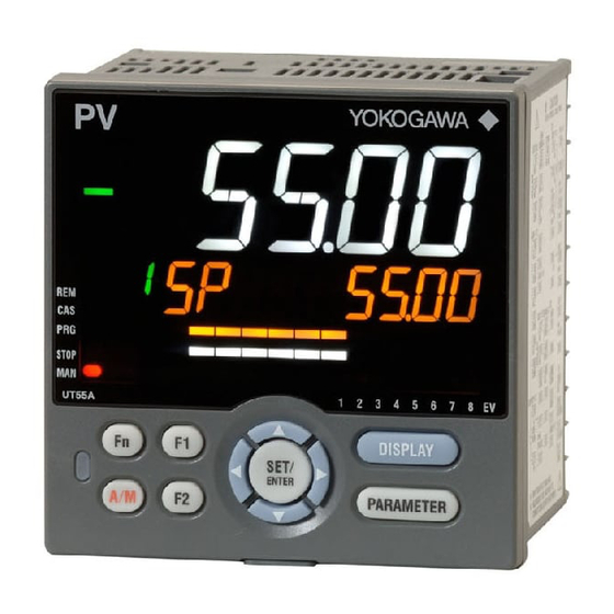
Setup Procedure
UTAdvanced Quick Setting
(Controlling Flow with Inverters)
Current input 4–20 mA
0.0–10.0 m3/h
Current output
4–20 mA
Inverter
Di2
COM
L
N
This document is subject to change without notice.
Electromagnetic
flow meter
Current input 4–20 mA
+
PV
-
Current output
4–20 mA
+
OUT
-
Electromagnetic
flow meter
Inverter
TI04L01L01-04EN
2011.12.16 1st Edition (YK)
Advertisement

Related Manuals for YOKOGAWA UT32A


Summary of Contents for YOKOGAWA UT32A
- Page 1 This is an example of wiring and settings using the UTAdvanced Quick Setting function for "flow control with inverters." For more details, see the user's manual. ■ Relevant models Standard models of the UT32A, UT35A, UT52A, and UT55A. ■ System Current input 4–20 mA 0.0–10.0 m3/h...
- Page 2 ■ Settings To set PID control, the input signal (4 to 20 mA), and current control output (4 to 20 mA), set the following parameters. (1) Select the desired parameter with the UP or DOWN key (2) Press SET/ENTER (the setting value blinks) (3) Change the setting with the UP or DOWN key Press SET/ENTER to set the new value (the setting value stops blinking but remains bright)
- Page 3 MAXIMUM MAXIMUM Set RH (maximum value of PV input range) to 20.00 mA (the initial value). VALUE OF PV VALUE OF PV INPUT RANGE INPUT RANGE 20.00 20.00 Set RL (minimum value of PV input range) to 4.00 mA (the initial value). MINIMUM MINIMUM VALUE OF PV...
- Page 4 Revision Information Document name: Setup Procedure: UTAdvanced Quick Setting (Controlling Flow with Inverters) Document number: TI 04L01L01-04EN First edition: December, 2011 Newly released TI 04L01L01-04EN 2011.12.16-00 This document is subject to change without notice.
Need help?
Do you have a question about the UT32A and is the answer not in the manual?
Questions and answers