Sign In
Upload
Manuals
Brands
YOKOGAWA Manuals
Controller
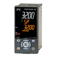
UTAdvanced UT32A
YOKOGAWA UTAdvanced UT32A Manuals
Manuals and User Guides for YOKOGAWA UTAdvanced UT32A. We have
8
YOKOGAWA UTAdvanced UT32A manuals available for free PDF download: User Manual, Technical Information, Operation Manual
YOKOGAWA UTAdvanced UT32A User Manual (236 pages)
Digital Indicating Controller
Brand:
YOKOGAWA
| Category:
Controller
| Size: 7 MB
Table of Contents
Introduction
4
Target Readers
4
Notice
5
Safety Precautions
5
Handling Precautions for the Main Unit
7
Checking the Contents of the Package
8
Model and Suffix Codes of UT32A (for Entry Model)
9
Symbols Used in this Manual
12
How to Use this Manual
13
Table of Contents
14
Chapter 1 Introduction to Functions
18
Quick Setting Function
18
Input/Output Function
19
Control Functions
20
Display and Key Functions
21
Communication Functions
22
Definition of Main Symbols and Terms
24
Chapter 2 Ut32A Operating Procedures
26
Chapter 3 Part Names
28
Names and Functions of Display Parts
28
Names and Functions of Keys
29
List of Display Symbols
31
Brief Description of Setting Details (Parameters)
33
Chapter 4 Basic Operation
34
Overview of Display Switch and Operation Keys
34
How to Set Parameters
37
Chapter 5 Quick Setting Function
42
Setting Using Quick Setting Function
42
Restarting Quick Setting Function
47
Chapter 6 Monitoring And Control Of Regular Operations
48
Monitoring and Control of Operation Displays
48
Operation Display Transitions
48
Setting Target Setpoint
52
Performing and Canceling Auto-Tuning
54
Adjusting PID Manually
57
Setting Alarm Setpoint
62
Selecting Target Setpoint Number (SPNO)
63
Switching Operation Modes
64
Switching between AUTO and man
64
Switching between STOP and RUN
66
Switching between REM (Remote) and LCL (Local)
68
Manipulating Control Output During Manual Operation
69
Releasing On-State (Latch) of Alarm Output
70
Chapter 7 Input (Pv) Functions
72
Setting Functions of PV Input
72
Setting Input Type, Unit, Range, Scale, and Decimal Point Position
72
Setting Burnout Detection for Input
74
Setting Reference Junction Compensation (RJC) or External Reference
75
Junction Compensation (ERJC)
75
Correcting Input Value
76
Setting Bias and Filter
76
Chapter 8 Control Functions
78
Control Function Block Diagrams
78
Single-Loop Control
78
Setting Control Type (CNT)
80
PID Control
81
ON/OFF Control (1 Point of Hysteresis / 2 Points of Hysteresis)
82
PD Control (Stable Control in Which a Setpoint Is Not Exceeded)
84
Setting PID Control Mode (ALG)
85
Switching PID
87
Switching PID According to Target Setpoint Number (SPNO)
87
Switching PID According to PV
88
Switching PID According to SP
90
Switching PID According to Target SP
92
Switching PID According to Deviation (Reference Deviation)
94
Setting Hysteresis at Time of PID Switch
95
Suppressing Overshoot (Super Function)
96
Suppressing Hunting (Super2 Function)
98
Suppressing Integral Action (Anti-Reset Wind-Up)
100
Adjusting Auto-Tuning Operation
101
Chapter 9 Auxiliary Control Functions
102
Setting SP Limiter
102
Changing SP at a Fixed Rate (SP Ramp-Rate Setting Function)
103
Forcing SP to Track PV (PV Tracking)
105
Forcing SP to Track Remote Input (SP Tracking)
106
Setting Controller Action at Power on (Restart Mode)
107
Setting Time between Powering on Controller and Starting Control (Restart Timer)
108
Chapter 10 Control Output Functions
110
Control Output Functions
110
Setting Control Output Cycle Time
111
Setting Limiter to Control Output
112
Disabling Output Limiter in man Mode
113
Setting Velocity Limiter to Control Output
114
Reducing 4-20 Ma Current Output to 0 Ma (Tight Shut Function)
115
Setting ON/OFF Control Hysteresis
116
Canceling Offset of PV and SP (Manual Reset)
118
Setting Preset Output Value
119
Setting Output Value in STOP Mode (Preset Output)
119
Setting Output Value When Switched to man Mode (Manual Preset Output)
120
Setting Output Value When Error Occurs (Input Error Preset Output)
121
Changing Current Output Range
122
Chapter 11 Alarm Functions
124
Setting Alarm Type
124
Setting Number of Alarm Groups to Use
135
Setting Hysteresis to Alarm Operation
136
Delaying Alarm Output (Alarm Delay Timer)
137
Setting Alarm Action According to Operation Mode
138
Chapter 12 Contact Output Functions
140
Contact Output Functions
140
Setting Function of Contact Output
140
Changing Contact Type of Contact Output
143
Chapter 13 Display, Key, And Security Functions
144
Setting Display Functions
144
Setting Active Color PV Display Function
144
Masking Arbitrary Display Value in Operation Display
147
Registering SELECT Display (up to 5 Displays)
148
Changing Event Display
149
Registering SELECT Parameter Display (up to 10 Displays)
150
Setting Bar-Graph Display Function
152
Masking Least Significant Digit of PV Display
154
Setting Economy Mode
155
Selecting the Initial Operation Display that Appears at Power on
155
Switching Guide Display Language
156
Changing Guide Scroll Speed
156
Turning Guide Display ON/OFF
156
Setting Automatic Return to Operation Display
157
Setting Brightness and Contrast Adjustment of LCD and Display Update Cycle
157
Assigning Function to User Function Key and A/M Key
158
Setting Security Functions
161
Setting/Canceling a Password
161
Setting Parameter Display Level
161
Locking (Hiding) Parameter Menu Display
162
Key Lock
163
Setting Display/Non-Display of Operation Display
163
Prohibiting Writing Via Communication
163
Confirmation of Key and I/O Condition and Version
164
Confirmation of Key and I/O Condition
164
Confirmation of Version
165
Chapter 14 Parameter Initialization
166
Initializing Parameter Settings to Factory Default Values
166
Registering and Initializing User Default Values
167
Registering as User Setting (Default) Values
167
Initializing to User Setting (Default) Values
167
Chapter 15 Power Failure Recovery Processing / Power Frequency Setting
168
Remedies if Power Failure Occurs During Operations
168
Power Frequency Setting
169
Chapter 16 Troubleshooting, Maintenance, And Inspections
170
Troubleshooting
170
Troubleshooting Flowchart
170
Errors at Power on
172
Maintenance
182
Cleaning
182
Packaging When Shipping the Product for Repair
182
Replacing Parts
182
Periodic Maintenance
183
Disposal
184
Chapter 17 Installation And Wiring
186
Installation Location
186
Mounting Method
188
External Dimensions and Panel Cutout Dimensions
189
Wiring
190
Important Information on Wiring
190
PV Input Wiring
192
Control Output (Relay, Current, and Voltage Pulse) Wiring
193
Contact Output Wiring
195
DC Loop Power Supply Wiring
196
Communication Interface Wiring
196
Coordinated Operation Wiring
198
Power Supply Wiring
200
Attaching and Detaching Terminal Cover
201
Chapter 18 Parameters
202
Parameter Map
202
List of Parameters
209
Operation Parameters
209
Setup Parameters
214
Revision Information
234
Advertisement
YOKOGAWA UTAdvanced UT32A User Manual (178 pages)
920 MHz Wireless Communication
Brand:
YOKOGAWA
| Category:
Other
| Size: 8 MB
Table of Contents
Introduction
3
Notes
5
Revisions
5
Trademarks
5
How to Use this Manual
6
Recorder Version and Functions Described in this Manual
6
What this Manual Explains
6
Conventions Used in this Manual
8
Revision History
9
Table of Contents
11
Chapter 1 Overview and Specifications
13
Overview
13
Specifications
14
Wireless Communication Function
14
Chapter 2 Configuration and Connection
17
Configuration
17
Preparation, Configuration, and Operation Check
17
Default Settings
19
Configuration Example (GX/GP-GM)
21
App
21
Configuration Example (GX/GP-UT)
25
Connection
29
Status LED Indication
29
Connecting an External Antenna
30
Chapter 3 Network Overview
33
Wireless Communication Option
33
Network Join Mode
33
When Wireless Devices Are Used as Low-Speed Moving Bodies
34
Multidrop Connection
35
Packet Filtering Setup
35
Functions
36
Network Numbers and Network Names
37
Channel Numbers
37
PAN ID (Group Number)
38
Network Names
38
Multi-Hop Communication
39
Network Participation and Route Configuration
39
Network Scale Setup
40
Monitoring Unit Time of Radio Transmission
40
Chapter 4 Using the Maintenance Console
41
Overview of the Maintenance Console
41
Configuration Function of the Maintenance Console
41
Installation
42
System Requirements
42
Installing the Maintenance Console
42
Connection and Startup
43
Connection Configuration
43
Starting and Closing the Maintenance Console
43
Maintenance Console's Main Window
44
Configuring the Maintenance Console Environment
45
Environment Setup Window
45
MAC Address List Window (Sub Window)
59
Station Number List Window (Sub Window)
62
Status Window
64
Setting the Network Scale (Network Scale Setup)
65
Configuring Router Modules
67
Setup Procedure
67
Router Configuration Selection Window
68
Router Configuration Window
69
Status Window
78
Setting the Network Scale (Network Scale Setup)
80
Configuring the Coordinator Module
82
Setup Procedure
82
Configuring the Coordinator Module (Low-Speed Moving Body)
82
Coordinator Configuration Selection Window
83
Coordinator Configuration Window
84
MAC Address List Window (Sub Window)
93
Station Number List Window (Sub Window)
97
Status Window
99
Setting the Network Scale (Network Scale Setup)
101
Configuring the Router Module (Low-Speed Moving Body)
103
Setup Procedure
103
Router Configuration Selection Window
104
Router Configuration Window
105
Status Window
112
Setting the Network Scale (Network Scale Setup)
114
Other Functions (Tool Menu)
116
Measurement Tool
123
Channel Noise Scan Tool
123
Communication Test Tool
128
Chapter 5 List of Settings
133
Overview of Configuration Files
133
Basic Configuration Items
134
Communication Setup Items
135
Protocol Setup Items
135
Packet Filtering Setup Items
135
Station Number Setup Items
136
Fixed Route Setup Items
136
Password Setup Items
136
Appendix
137
YOKOGAWA UTAdvanced UT32A Operation Manual (13 pages)
Digital Indicating Controllers
Brand:
YOKOGAWA
| Category:
Controller
| Size: 7 MB
Table of Contents
Hardware Specifications
2
IM 05P01D31-11En
2
Terminal Wiring Diagrams
3
Names and Functions of Display Parts
5
Setup Procedure
5
Setting Alarm Setpoint
6
Switching between AUTO and man
6
Performing/Canceling Auto-Tuning
7
Troubleshooting
8
Switching between REM (Remote) and LCL (Local
8
Operation Parameters
9
Press the SET/ENTER Key to Start the
9
Setup Parameters
10
Advertisement
YOKOGAWA UTAdvanced UT32A Technical Information (18 pages)
Digital Indicating Controller
Brand:
YOKOGAWA
| Category:
Controller
| Size: 0 MB
Table of Contents
Names and Functions of Display Parts
3
List of Display Symbols
8
Setup Parameter Map
10
Setup Parameters
13
YOKOGAWA UTAdvanced UT32A Technical Information (3 pages)
Setup Procedure UTAdvanced Quick Setting (Controlling Tank Temperature)
Brand:
YOKOGAWA
| Category:
Controller
| Size: 0 MB
Table of Contents
Foreword
1
Overview
1
Relevant Models
1
System
1
Wiring
1
Settings
2
Redoing the Quick Setting
2
Maximum Value of PV Input Range
3
Minimum Value of PV Input Range
3
Output Type Selection
3
Control Output Cycle Time
3
Revision Information
3
YOKOGAWA UTAdvanced UT32A Technical Information (3 pages)
Controlling Furnace Temperature with a Motorized Valve
Brand:
YOKOGAWA
| Category:
Controller
| Size: 0 MB
Table of Contents
Overview
1
Relevant Models
1
System
1
Wiring
1
Settings
2
Redoing the Quick Setting
2
Maximum Value of Pv Input Range
3
Minimum Value of Pv Input Range
3
Finish
3
Revision Information
3
YOKOGAWA UTAdvanced UT32A Technical Information (3 pages)
Setup Procedure UTAdvanced Quick Setting (Controlling Furnace Temperature with a Thyristor)
Brand:
YOKOGAWA
| Category:
Controller
| Size: 0 MB
Table of Contents
Overview
1
Relevant Models
1
System
1
Wiring
1
Settings
2
Redoing the Quick Setting
2
Revision Information
3
YOKOGAWA UTAdvanced UT32A Technical Information (4 pages)
Setup Procedure UTAdvanced Quick Setting (Controlling Flow with Inverters)
Brand:
YOKOGAWA
| Category:
Controller
| Size: 0 MB
Advertisement
Related Products
YOKOGAWA UT320
YOKOGAWA UT32A/RSP
YOKOGAWA UT32A-V
YOKOGAWA UT32A-R
YOKOGAWA UT32A-C
YOKOGAWA UT32A-D
YOKOGAWA UT321
YOKOGAWA UT351
YOKOGAWA UT35A-L
YOKOGAWA UT350
YOKOGAWA Categories
Measuring Instruments
Test Equipment
Transmitter
Controller
Media Converter
More YOKOGAWA Manuals
Login
Sign In
OR
Sign in with Facebook
Sign in with Google
Upload manual
Upload from disk
Upload from URL