
Related Manuals for YOKOGAWA UT321


Summary of Contents for YOKOGAWA UT321
- Page 1 User’s Manual Model UT351/UT321 Digital Indicating Controllers User’s Manual IM 05D01D12-41E IM 05D01D12-41E 4th Edition...
- Page 2 Blank Page...
-
Page 3: Introduction
(2) Read this manual carefully to gain a thorough understanding of how to operate this product before starting operation. (3) This manual describes the functions of this product. Yokogawa M&C Corporation (hereinafter simply referred to as Yokogawa) does not guarantee the application of these functions for any particular purpose. - Page 4 Draws attention to information that is essential for understanding the operation and/or features of the controller. Regarding Force Majeure Yokogawa M&C Corporation assumes no liability for any loss or damage, direct or indirect, caused by the use of or unpredictable defects of the product. IM 05D01D12-41E...
-
Page 5: Table Of Contents
Toc-1 <Int> <Rev> Model UT351/UT321 Digital Indicating Controllers User’s Manual IM 05D01D12-41E 4th Edition CONTENTS Introduction......................i Installation ....................1-1 Model and Suffix Codes .................. 1-1 How to Install ....................1-2 How to Connect Wires ..................1-5 Hardware Specifications ................1-7 Terminal Wiring Diagrams ................ - Page 6 Toc-2 <Int> <Rev> Parameters ....................5-1 Parameter Map ....................5-1 Lists of Parameters ..................5-4 Function Block Diagram and Descriptions..........6-1 Revision Information .................... i IM 05D01D12-41E 4th Edition : Sep 01,2003-00...
-
Page 7: Installation
Before using the controller, check that the model and suffix codes match your order. Model Suffix Code Description UT351 Digital indicating controller (provided with retransmission output and 15 V DC loop power supply as standard) UT321 Standard type Type Heating/cooling type Standard type (with 24 V DC loop power supply) None Optional functions... -
Page 8: How To Install
<Toc> <1. Installation> How to Install NOTE To install the controller, select a location where: no one may accidentally touch the terminals, mechanical vibrations are minimal, 150mm corrosive gas is minimal, temperature can be maintained at about 23 C and 150mm 150mm the fluctuation is minimal,... - Page 9 145 min. "N" stands for the number of controllers to be installed. However, the measured value applies if N +0.8 +0.8 (25) UT321 Unit: mm Small bracket Small bracket 1 to 10 mm (Panel thickness) General installation Side-by-side close installation 70 min.
- Page 10 <Toc> <1. Installation> How to Install Turn off the power to the controller before installing it on the panel because there is a possibility of electric shock. CAUTION After opening the mounting hole on the panel, follow the procedures below to install the controller: Insert the controller into the opening from the front of the panel so that the terminal board on the rear is at the far side.
-
Page 11: How To Connect Wires
When there is possibility of being struck by external lightening surge, use the arrester to protect the instrument. For DC Relay Wiring For AC Relay Wiring UT351/UT321 External AC power supply UT351/UT321 External DC power supply Diode (Mount it directly UT’s contact... - Page 12 Power supply, grounding, relay contact outputs 600 V PVC insulated wires, JIS C 3307, 0.9 to 2.0 mm Thermocouple Shielded compensating lead wires, JIS C 1610, (See Yokogawa Electric's GS 6B1U1-E.) Shielded wires (three conductors), UL2482 (Hitachi Cable) Other signals Shielded wires...
-
Page 13: Hardware Specifications
21.6 to 28.0 V DC, max. 30 mA (only for models with 24 V DC loop power supply) When using the 24 V DC loop power supply of the UT321, keep the operating ambient temperature between 0 C and 40 C. - Page 14 <Toc> <1. Installation> Retransmission Output Either PV, target setpoint, or control output is output. Either the retransmission output or the loop power supply can be used with terminals • Number of outputs: 1 (terminals • Output signal: 4-20 mA DC •...
- Page 15 UT351: 4-digit, 7-segment green or red LED display, character height of 20 mm UT321: 4-digit, 7-segment green or red LED display, character height of 12 mm • Setpoint display: 4-digit, 7-segment red LED display, character height of 9.3 mm (for both UT351 and UT321) •...
- Page 16 1-10 <Toc> <1. Installation> Power Supply Specifications • Power supply: Rated voltage of 100 to 240 V AC ( 10%), 50/60 Hz • Power consumption: Max. 20 VA (8.0 W max.) • Internal fuse rating: 250 V AC, 1.6A time-lug fuse •...
- Page 17 Ambient temperature: 0 to 50 C (40 C or less for side-by-side close installation) The operating ambient temperature range is between 0 C and 40 C when the 24 V DC loop power supply of the UT321 is used. Temperature change rate: 10 C/h or less...
-
Page 18: Terminal Wiring Diagrams
1-12 <Toc> <1. Installation> Terminal Wiring Diagrams NOTE Do not use unassigned terminals as relay terminals. Terminal wiring diagrams are shown on and after the next page. IM 05D01D12-41E 4th Edition : Sep 01,2003-00... -
Page 23: Initial Settings
<Toc> <2. Initial Settings> Initial Settings This chapter describes examples of setting PV input types, control output types, and alarm types. Carrying out settings described herein allows you to perform basic control. Refer to examples of various settings to understand how to set parameters required. -
Page 24: Names And Functions Of Front Panel Parts
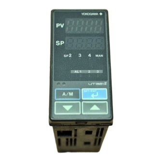
<Toc> <2. Initial Settings> Names and Functions of Front Panel Parts UT351 UT321 1. Process 1. Process variable (PV) variable (PV) 3. Target setpoint 2. Setpoint display display (SP) number display 2. Setpoint 4. Status indicator lamps display indicator lamp 3. -
Page 25: Setting Pv Input Type (Setting First At Power-On)
<Toc> <2. Initial Settings> Setting PV Input Type (Setting First at Power-on) NOTE • The controller displays the operating display when the power is turned on. However, if PV input type has not been set, “IN” appears. In this case, first use the key to display the input range code to use, then press the key to register it. - Page 26 <Toc> <2. Initial Settings> Press the key once to register the Press the key once to display the SET/ENT SET/ENT required setpoint. parameter “RL” (minimum value of PV input range). Displays parameter “RL”. A / M SET/ENT A / M SET/ENT Press the SET/ENT...
- Page 27 <Toc> <2. Initial Settings> Instrument Input Range Codes Select the unit from the UNIT parameter. Instrument Input Instrument Input Type Measurement Accuracy Range Code Input Range Set the data item PV Input Type "IN" to the OFF option to leave the PV input Unspecified type undefined.
-
Page 28: Changing Pv Input Type
<Toc> <2. Initial Settings> Changing PV Input Type The following operating procedure describes an example of changing the K-type thermo- couple (-199.9 C to 500.0 C) to a Pt100 resistance temerature detector (-199.9 C to 500.0 C) and setting the measurement range of 0.0 C to 200.0 C. PV input terminal Thermocouple/mV/V input...... - Page 29 <Toc> <2. Initial Settings> Press the key once to register the Press the key once to display the SET/ENT SET/ENT setpoint. parameter “RL” (minimum value of PV input range). Displays parameter “RL”. A / M SET/ENT A / M SET/ENT Press the SET/ENT key once to display the...
-
Page 30: Setting Control Output Type
<Toc> <2. Initial Settings> Setting Control Output Type The following operating procedure describes an example of changing time proportional PID relay output (0: factory-set default) to current output (2). Control output terminal Values in parentheses are setpoints Time proportional PID relay (0)/on-off(3) output......Current (2)/time proportional PID voltage pulse (1) output..... -
Page 31: Changing Alarm Type
<Toc> <2. Initial Settings> Press the key once to register the Press the key for more than 3 sec- SET/ENT SET/ENT setpoint. onds. This returns you to the display shown at power-on (figure below). Displays PV. Displays A / M target setpoint. - Page 32 2-10 <Toc> <2. Initial Settings> Press the key once to display the Press the key once to register the SET/ENT SET/ENT menu “FUNC”. setpoint. You can take the same steps for alarm-2 type (AL2), and alarm-3 type (AL3) that are Displays displayed after this.
- Page 33 2-11 <Toc> <2. Initial Settings> List of Alarm Types The table below shows the alarm types and alarm actions. In the table, codes 1 to 10 are not provided with stand-by actions, while codes 11 to 20 are provided with stand-by actions. Alarm type code Alarm type code Alarm action...
- Page 34 2-12 <Toc> <2. Initial Settings> It is effective in the following cases where; Stand-by Action - the power is turned on - the target setpoint is changed - the target setpoint number is switched (however, except for remote setpoint) Normal Abnormal Treated The alarm...
-
Page 35: Setting The Pv Display Color Changing Function "Active Color Pv Display"2-13
2-13 <Toc> <2. Initial Settings> Setting the PV Display Color Changing Function “Active Color PV Display” The following operating procedure describes an example of changing PV color mode (factory-set default : Fixed in red mode) to Link to alarm 1 mode. Bring the operating display into view (appears at Press the key several times to display the... -
Page 36: Setting The High Limit And Low Limit For Pv Color Change
SET/ENT Description of Multiple Setpoints and PID The UT351/UT321 controllers have a maximum of four target setpoint (SP) parameters and has PID for each of these setpoints. The following shows the correspondence between the target setpoint numbers (SP.NO), target setpoints (SP), and PID parameters. -
Page 37: Operations
<Toc> <3. Operations> Operations This chapter describes key entries for operating the controller. For operations using external contact inputs, see “1.5 Terminal Wiring Diagrams.” If you cannot remem- ber how to carry out an operation during setting, press the key for more than 3 SET/ENT seconds. - Page 38 <Toc> <3. Operations> Operating Displays for a Heating/Cooling Controller SP Display The PV input value appears on the PV display. The target setpoint (1.SP) appears on the Setpoint display. Heating/Cooling OUT Display The PV input value appears on the PV display. The heating (H) and cooling (C) sides control output values appears on the Setpoint dis- play.
-
Page 39: Setting Target Setpoint (Sp)
<Toc> <3. Operations> Setting Target Setpoint (SP) The following operating procedure describes an example of setting 120.0 to a target setpoint. In automatic operation, the controller starts control using set target setpoints. NOTE When the target setpoint is set through communication, the target setpoint cannot be changed by keystroke. -
Page 40: Performing/Canceling Auto-Tuning
<Toc> <3. Operations> Performing/Canceling Auto-tuning Auto-tuning should be carried out after setting a target setpoint (SP). Make sure the control- ler is in automatic operation mode (AUTO) and running state (RUN) before carrying out auto-tuning. See “ 3.8 Switching between AUTO and MAN,” to change to AUTO and “ 3.7 Switching between Run and Stop,”... -
Page 41: Setting Pid Manually
<Toc> <3. Operations> Press the key once to register the During auto-tuning, the panel indications SET/ENT setpoint. (This starts auto-tuning.) become as shown below. If the key is pressed when AT = OFF, SET/ENT auto-tuning will be cancelled. In this case, PID contains the value existing before auto-tuning. -
Page 42: Setting Alarm Setpoints
<Toc> <3. Operations> [TIP] Press the key to display the The PID parameter numbers set in step 4. required setpoint. should be set as follows: In case of PID for 1.SP, PID = 1Gr In case of PID for 2.SP, PID = 2Gr In case of PID for 3.SP, PID = 3Gr In case of PID for 4.SP, PID = 4Gr Blinks during... -
Page 43: Selecting Target Setpoint Numbers (Sp.no)
<Toc> <3. Operations> Press the key twice to display the Press the key once to register the SET/ENT SET/ENT parameter “A1”. setpoint. Displays parameter “A1”. A / M A / M SET/ENT SET/ENT Also configure the Alarm-2 Setpoint (A2) and Alarm-3 Setpoint (A3) parameters that Press the key to display the follow this step. -
Page 44: Switching Between Run And Stop
<Toc> <3. Operations> Press the key several times to Press the key once to register the SET/ENT SET/ENT display the parameter “SP.NO”. setpoint. Displays parameter “SP.NO”. A / M A / M SET/ENT SET/ENT Press the SET/ENT key for more than 3 sec- Press the key to display the onds. -
Page 45: Switching Between Auto And Man
<Toc> <3. Operations> Switching between AUTO and MAN NOTE If AUTO and MAN have been switched using contact input, when the contact input is ON, switching between AUTO and MAN cannot be achieved by keystroke. Bring the operating display into view (display appears at power on). Displays PV. -
Page 46: Manipulating Control Output In Manual Operation
3-10 <Toc> <3. Operations> Manipulating Control Output in Manual Operation NOTE Control output cannot be changed if the controller is stopped. In this case, the preset output value (setup parameter PO) will be output. A control output value is linked with a display value changed using the key. - Page 47 3-11 <Toc> <3. Operations> Controller Behavior and Control Output Manipulation when the Dead Band is Positive The following is an example when the DB parameter is set at 12.4%. If you hold down the key with the heating-side output under manipulation (i.e., cooling- side output C = 0.0%), the heating-side output (H =) decreases.
- Page 48 Blank Page...
-
Page 49: Troubleshooting And Maintenance
<Toc> <4. Troubleshooting and Maintenance> Troubleshooting and Maintenance Troubleshooting Troubleshooting Flow If the operating display does not appear after turning on the controller’s power, follow the measures in the procedure below. If a problem appears complicated, contact our sales representative. Is the instrument defective? Is key... - Page 50 <Toc> <4. Troubleshooting and Maintenance> Errors at Power on The following table shows errors that may be detected by the fault diagnosis function when the power is turned on. Error indication Description Control Alarm Retransmission Communi- Remedy (on PV display unit) of error output output...
- Page 51 The Controller does not Show the measured input (PV). • The UT351/UT321 controllers have a universal input. The type of PV input can be set/changed using the parameter “IN”. At this point, the controller must be wired correctly according to the selected type of PV input.
-
Page 52: Maintenance
<Toc> <4. Troubleshooting and Maintenance> Maintenance This section describes the cleaning and maintenance of the UT351/UT321. 4.2.1 Cleaning The front panel and operation keys should be gently wiped with a dry cloth. NOTE Do not use alcohol, benzine, or any other solvents. - Page 53 <Toc> <4. Troubleshooting and Maintenance> Attaching Terminal Cover The procedure for attaching the terminal cover is as follows. Do not touch the terminals on the rear panel when power is being supplied to the controller. Doing so may result in electric shock. Before attaching the terminal cover, turn off the source circuit breaker and use a tester to CAUTION check that the power cable is not conducting any electricity.
-
Page 54: Replacing Parts With A Limited Service Life
<Toc> <4. Troubleshooting and Maintenance> 4.2.4 Replacing Parts with a Limited Service Life The following UT351/UT321 parts have a limited service life. The service life given in the table assume that the controller is used under normal operating conditions. Part... -
Page 55: Replacing Control Output Relays
<Toc> <4. Troubleshooting and Maintenance> 4.2.5 Replacing Control Output Relays This subsection describes how to replace the control output relays. The replacement must be performed by an engineer qualified for the work. Always turn off the power before starting the work in order to avoid electric shock. Do not pull out the internal unit for any other purpose other than to replace the control output relays. - Page 56 Confirm the location of the control output relay to be replaced before pulling out the relay. Upper Relay (UT351-0 or UT321-0 ) Pull out the relay to be replaced. The control output relays are easy to remove and mount, since they are connected via a socket onto the print boards.
- Page 57 <Toc> <4. Troubleshooting and Maintenance> Insert the internal unit into the housing. Apply power to the controller and confirm that the initial operating display is shown. If the operating display is not shown properly, turn off the controller and pull out the internal unit.
- Page 58 Blank Page...
-
Page 59: Parameters
<Toc> <5. Parameters> Parameters This chapter contains a parameter map as a guideline for setting parameters, and lists of parameters for recording User Settings. Parameter Map IM 05D01D12-41E 4th Edition : Sep 01,2003-00... - Page 60 <Toc> <5. Parameters> UT351/UT321 Parameter Map Operating Display SP display OUT display SET3S SET3S SET3S Menu OP.PA To switch the parameter display, press the SET/ENT key. Not displayed when OT parameter set to 4 to 6. Displayed in automatic Pressing the...
- Page 61 <Toc> <5. Parameters> SET/ENT Press the key once. SET/ENT SET3S Press the key for 3 seconds. Press the key once. STUP Password input Password (No password is required check display when PWD = 0.) Setup Parameter Setting Display Control function Input/Output related related...
-
Page 62: Lists Of Parameters
<Toc> <5. Parameters> Lists of Parameters * Parameters relating to PV or setpoints should all be set in real numbers. For example, use temperature values to define target setpoints and alarm setpoints for temperature input. * The “User Setting” column in the table is provided for the customer to record setpoints. * The column “Target Item in CD-ROM”... - Page 63 <Toc> <5. Parameters> Parameter Target Item Name of Parameter Setting Range and Description Initial Value User Setting Symbol in CD-ROM PV input filter OFF (0), 1 to 120 second. OFF (0) Used when the PV input fluctuates. (FL) Ref.1.1(1) PV input bias -100.0% to 100.0% of PV input 0.0% of PV input range range span...
- Page 64 <Toc> <5. Parameters> PID-related Parameters The following parameters are displayed when “1Gr” is set to PID parameter display number (PID). In this case, the corresponding target setpoint is 1.SP (target setpoint-1). To set PID corresponding to target setpoint 2 to 4, set “2Gr”, “3Gr”, or “4Gr” to PID. The relevant parameters will then be displayed.
- Page 65 PID constants. This function does not work when the controller is performing on-off control. The UT351/UT321 employ the “Limit Cycle Method.” As shown in the figure below, the controller temporarily changes its control output in a step-waveform manner.
- Page 66 <Toc> <5. Parameters> Hysteresis (for Target Setpoints (On-Off Control) and Alarm Setpoints) Hysteresis can be set in on-off control setpoints and alarm setpoints as well. With the hysteresis settings, it is possible to prevent relays from chattering. • When hysteresis is set in a target setpoint Point of on-off action Output (Target setpoint)
- Page 67 <Toc> <5. Parameters> The figure below shows an example when the Target Setpoint Number (SP.NO) parameter is switched. The 1.SP and 2.SP parameters are set to 500°C and 640°C, respectively. Thus, there is a temperature difference of 140°C between the 1.SP and 2.SP parameters. This example shows how the temperature is changed by as much as this temperature difference over a period of two minutes.
- Page 68 5-10 <Toc> <5. Parameters> Setup Parameters Control Function-related Parameters Parameter Target Item Name of Parameter Setting Range and Description Initial Value User Setting Symbol in CD-ROM Target setpoint limiter 0.0 to 100.0% of PV input range where, SPL < SPH 100.0% of upper limit Places a limit on the range within which the target...
- Page 69 5-11 <Toc> <5. Parameters> Parameter Target Item Name of Parameter Setting Range and Description Initial Value User Setting Symbol in CD-ROM PID control mode 0: Standard PID control (with output bump at SP change) 1: Fixed Point control (without output bump at SP change) Ref.2.1(2) (C.MD) Choose “Fixed Point Control”...
- Page 70 5-12 <Toc> <5. Parameters> Input-/Output-related Parameters Parameter Target Item Name of Parameter Setting Range and Description Initial Value User Setting Symbol in CD-ROM PV input type (PV INPUT OFF (0), 1 to 18, 30, 31, 35 to 37, 40, 41, 50, 51, 55, 56 OFF (0) terminals) See “Instrument Input Range Codes”...
- Page 71 5-13 <Toc> <5. Parameters> Parameter Target Item Name of Parameter Setting Range and Description Initial Value User Setting Symbol in CD-ROM Retransmission output 1: PV, 2: SP, 3: OUT, 4: Loop power supply for sensor (15 V) type In heating/cooling control, an output value before allocation to heating and cooling control (0 to 100%) is transmitted if setpoint “3”...
- Page 72 5-14 <Toc> <5. Parameters> Functions of Active Color PV Display This part describes the functions of “Active Color PV Display.” PV display color is changed by the following four actions. PV display is selectable from red-to-green or green-to-red changing action, or fixed color. Link to alarm 1 mode (when PCMD = 2, 3) (Setting example-1) Link to alarm 1 and 2 mode (when PCMD = 4, 5) is the same.
- Page 73 5-15 <Toc> <5. Parameters> Setting Example-3 : Link to PV Set high limit “70°C” for PCCH, and low limit “20°C” for PCCL. PV display color is changed from green to red when PV input value is out of the range. The red-to-green changing action is selectable.
- Page 74 External RJC is not a compensation function built in a controller but a compensation func- tion working outside the controller. External RJC is used when input is thermocouple, and RJC=OFF. Using External RJC makes the accuracy of RJC higher and shortens the compensating wire.. UT351/UT321 Terminal block Compensating wire Thermocouple Furnace...
- Page 75 5-17 <Toc> <5. Parameters> Useful Operating Displays (SELECT Display) Registering frequently changed parameters in the SELECT display after ordinary operating displays will allow you to change settings easily. A maximum of four displays can be regis- tered. Useful operating display (SELECT display) Ordinary operating displays (example) S E T / E N T...
- Page 76 5-18 <Toc> <5. Parameters> Heating/Cooling Control (for a Heating/Cooling Controller Only) In heating/cooling control, the controller outputs the result of computation after splitting it into heating-purpose and cooling-purpose signals. In addition, the controller can perform PID control or on-off control on the heating and cooling sides separately. When performing on-off control, set the proportional band to “0”.
- Page 77 5-19 <Toc> <5. Parameters> Cycle Time A cycle time can only be set if the type of control output is time proportional PID relay output or time proportional voltage pulse output. A cycle time refers to one period consisting of on-and off-state time lengths. The ratio of the on-state time to the off-state time differs according to the value of the control output.
- Page 78 Blank Page...
-
Page 79: Function Block Diagram And Descriptions
<Toc> <6. Function Block Diagram and Descriptions> Function Block Diagram and Descriptions This chapter contains the function block diagrams for “Standard type,” and “Heat- ing/cooling type.” For details on these function block diagrams, refer to the descrip- tions mentioned later. IM 05D01D12-41E 4th Edition : Sep 01,2003-00... - Page 80 <Toc> <6. Function Block Diagram and Descriptions> Function Block Diagram for Standard Type PV input terminals Communication terminals Contact input PV INPUT RS485 Input selection Unit selection Input range conversion Input bias Input filter SP.NO Target setpoints 1 to 4 REMOTE LOCAL SP.NO=0...
- Page 81 <Toc> <6. Function Block Diagram and Descriptions> Function Block Diagram for Heating/Cooling Type PV input terminals Communication terminals Contact input PV INPUT RS485 Input selection Unit selection Input range conversion Input bias Input filter SP.NO Target setpoints 1 to 4 REMOTE LOCAL SP.NO=0...
- Page 82 <Toc> <6. Function Block Diagram and Descriptions> Functions and Parameters for “Standard Type” in Initial State (Factory-set default) Functions and parameters in initial state are given in the tables below. For details on each parameter, refer to “5.2 Lists of Parameters.” PV Input PV input (INPUT) is a universal input, which can receive signals from thermocouple, RTD, or DC voltage signals.
- Page 83 <Toc> <6. Function Block Diagram and Descriptions> Contact Input Changing the setpoint of the parameter DIS (DI function selection) allows you to change the function of contact input. When DIS=OFF No function for contact input. When DIS=1 (factory-set default) Target setpoint 2 (ON)/Target setpoint 1 (OFF) switching function is assigned to DI1 (con- tact input 1).
- Page 84 <Toc> <6. Function Block Diagram and Descriptions> Target Setpoint and PID It is possible to use a maximum of four groups of target setpoints and PID parameters. The target setpoint can be selected by key operation or contact input. For selection by contact input, refer to “Contact Input.”...
- Page 85 <Toc> <6. Function Block Diagram and Descriptions> Control Output Control output (OUTPUT1) selects the output type among the current output, voltage pulse output, and relay contact output signal. Preset output value is output when the operation is stopped by key operation or contact input, which takes priority over the manual operation.
- Page 86 <Toc> <6. Function Block Diagram and Descriptions> Retransmission Output PV, target setpoint, or control output can be output to retransmission output (OUTPUT2/ RET). Each function can be set by the following parameters. Setup Parameters Function Parameter Menu Retransmission output type Retransmission output scale RTH, RTL 15 V DC Loop Power Supply...
-
Page 87: Revision Information
Complies with safety and EMC standards. Jun 2003/3rd Edition Addition of Model UT321. Sep 2003/4th Edition Complies with safety and EMC standards for Model UT321. Written by Yokogawa M&C Corporation Published by Yokogawa M&C Corporation 2-9-32 Nakacho, Musashino-shi, Tokyo 180-8750, JAPAN... - Page 88 Blank Page...
- Page 89 Sales Branch Offices / Houten (Netherlands), Wien (Austria), Zaventem (Belgium), Ratingen (Germany), Madrid (Spain), Bratislava (Slovakia), Runcorn (United Kingdom), Milano (Italy), Velizy villacoublay(France), Johannesburg(Republic of South Africa) YOKOGAWA AMERICA DO SUL S.A. Headquarters & Plant Praca Acapulco, 31-Santo Amaro, Sao Paulo/SP, CEP-04675-190 BRAZIL Phone: +55-11-5681-2400 Facsimile: +55-11-5681-1274/4434 YOKOGAWA ENGINEERING ASIA PTE.
Need help?
Do you have a question about the UT321 and is the answer not in the manual?
Questions and answers