Sign In
Upload
Manuals
Brands
YOKOGAWA Manuals
Temperature Controller
UTAdvanced UT55A
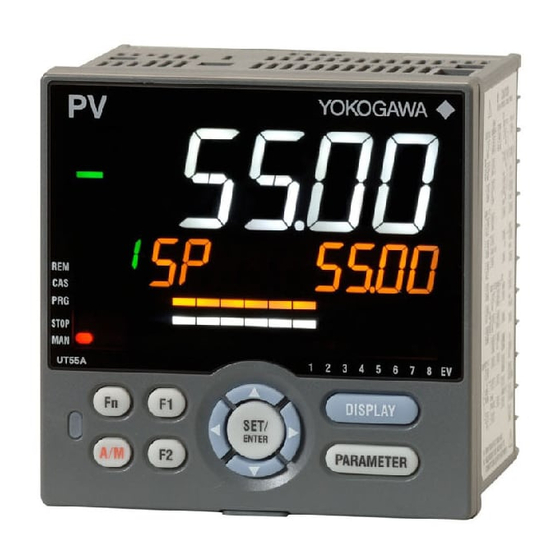
YOKOGAWA UTAdvanced UT55A Controller Manuals
Manuals and User Guides for YOKOGAWA UTAdvanced UT55A Controller. We have
7
YOKOGAWA UTAdvanced UT55A Controller manuals available for free PDF download: User Manual, Operation Manual, Technical Information
YOKOGAWA UTAdvanced UT55A User Manual (476 pages)
Digital Indicating Controllers
Brand:
YOKOGAWA
| Category:
Temperature Controller
| Size: 12 MB
Table of Contents
Contents
4
Trademarks
5
Safety Precautions
5
Handling Precautions for the Main Unit
7
Waste Electrical and Electronic Equipment (WEEE), Directive 2002/96/EC
7
Checking the Contents of the Package
8
Model and Suffix Codes of UT55A (for Standard Model)
9
Model and Suffix Codes of UT52A (for Standard Model)
10
Model and Suffix Codes of UT55A (for Detailed Model)
11
Model and Suffix Codes of UT52A (for Detailed Model)
12
Symbols Used in this Manual
15
How to Use this Manual
16
Table of Contents
18
Introduction
4
Notice
4
Target Readers
4
Chapter 1 Introduction To Functions
26
Quick Setting Function
26
Input/Output Function
27
Control Functions
29
Control Mode
29
Display and Key Functions
33
Ladder Sequence Function
34
Communication Functions
35
Definition of Main Symbols and Terms
39
Chapter 2 UT55A/UT52A Operating Procedures
40
UT55A/UT52A Operating Procedures
40
Chapter 3 Part Names
42
Names and Functions of Display Parts
42
Names and Functions of Keys
45
List of Display Symbols
48
Brief Description of Setting Details (Parameters)
50
Chapter 4 Basic Operation
52
Overview of Display Switch and Operation Keys
52
How to Set Parameters
55
Chapter 5 Quick Setting Function App
60
Setting Using Quick Setting Function
60
Restarting Quick Setting Function
65
Chapter 6 Monitoring And Control Of Regular Operations
66
Monitoring and Control of Operation Displays
66
Operation Display Transitions in Single-Loop Control, Cascade Primary-Loop Control, Cascade Secondary-Loop Control, Loop Control for Backup, and Loop Control with PV-Hold Function
66
Standard Type
66
Position Proportional Type
67
Heating/Cooling Type
68
Single-Loop Two-Position Two-Level Control
69
Operation Display Transitions in Loop Control with PV Switching and Loop Control with PV Auto-Selector
70
Standard Type
70
Position Proportional Type
71
Heating/Cooling Type
72
Operation Display Transitions in Cascade Control
73
Standard Type
73
Position Proportional Type
75
Heating/Cooling Type
77
Analog Input
83
Setting Target Setpoint
84
Operation in the Operation Display
84
Operation in Parameter Setting Display
85
Performing and Canceling Auto-Tuning
86
Adjusting PID Manually
89
Setting Alarm Setpoint
95
Selecting Target Setpoint Number (SPNO)
96
Switching Operation Modes
97
Switching between AUTO and man
97
Direct Operation by A/M Key
97
Switching between cas (Cascade), AUTO, and man
99
Switching between STOP and RUN
101
Switching between REM (Remote) and LCL (Local)
103
Manipulating Control Output During Manual Operation
105
Releasing On-State (Latch) of Alarm Output
106
Chapter 7 Input (Pv, Remote, And Auxiliary Analog) Functions
108
Setting Functions of PV Input, Remote Input, and Auxiliary Analog Input
108
Setting Input Type, Unit, Range, Scale, and Decimal Point Position
108
Setting Burnout Detection for Input
112
Compensation (ERJC)
113
Setting Reference Junction Compensation (RJC) or External Reference Junction Compensation (ERJC)
113
Correcting Input Value
114
Setting Bias and Filter
114
Setting Square Root Extraction and Low Signal Cutoff Point
116
Setting 10-Segment Linearizer
117
Setting Ratio Bias/Filter
119
Setting Input Sampling Period (Control Period)
120
Using 4-Wire RTD as PV Input
121
Using Larger, Smaller, Average, or Difference of Two to Four Inputs as PV
122
Setting Remote Input Method
123
Adjusting PV Range for Loop Control with PV Switching or Loop Control with PV Auto-Selector
124
Setting PV Switching Methods of Loop Control with PV Switching
125
Chapter 8 Control Functions
130
Setting Control Mode (CTLM)
130
Single-Loop Control, Single-Loop Heating/Cooling Control, Single-Loop Position Proportional Control, and Single-Loop Two-Position Two-Level Control
130
Single-Loop Control Function Block Diagram
131
Single-Loop Heating/Cooling Control Function Block Diagram
133
Single-Loop Position Proportional Control Function Block Diagram
135
Single-Loop Two-Position Two-Level Control Function Block Diagram
137
Cascade Primary-Loop Control
140
Cascade Primary-Loop Control Function Block Diagram
141
Cascade Secondary-Loop Control, Cascade Secondary-Loop Heating/Cooling Control, and Cascade Secondary-Loop Position Proportional Control
144
Cascade Secondary-Loop Control Function Block Diagram
145
Cascade Secondary-Loop Heating/Cooling Control Function Block Diagram
147
Cascade Secondary-Loop Position Proportional Control Function Block Diagram
149
Cascade Control, Cascade Heating/Cooling Control, and Cascade Position Proportional Control
152
Cascade Control Function Block Diagram
153
Cascade Heating/Cooling Control Function Block Diagram
155
Cascade Position Proportional Control Function Block Diagram
157
Loop Control for Backup, Heating/Cooling Loop Control for Backup, and Position Proportional Loop Control for Backup
160
Loop Control for Backup Function Block Diagram
161
Heating/Cooling Loop Control for Backup Function Block Diagram
163
Position Proportional Loop Control for Backup Function Block Diagram
165
Loop Control with PV Switching, Heating/Cooling Loop Control with PV Switching, and Position Proportional Loop Control with PV Switching
168
Loop Control With Pv Switching Function Block Diagram
169
Heating/Cooling Loop Control With Pv Switching Function Block Diagram
171
Position Proportional Loop Control With Pv Switching Function Block Diagram
173
Loop Control with PV Auto-Selector, Heating/Cooling Loop Control with PV Auto-Selector, and Position Proportional Loop Control with PV Auto-Selector
176
Loop Control With Pv Auto-Selector (2 Inputs) Function Block Diagram
177
Heating/Cooling Loop Control With Pv Auto-Selector (2 Inputs) Function Block Diagram
179
Position Proportional Loop Control With Pv Auto-Selector (2 Inputs) Function Block Diagram
181
Loop Control With Pv Auto-Selector (4 Inputs) Function Block Diagram (Only For Ut55A)
183
Heating/Cooling Loop Control with PV Auto-Selector (4 Inputs) Function Block Diagram (Only for UT55A)
185
Position Proportional Loop Control with PV Auto-Selector (4 Inputs) Function Block Diagram (Only for UT55A)
187
Loop Control with PV-Hold Function, Heating/Cooling Loop Control with PV-Hold Function, and Position Proportional Loop Control with PV-Hold Function
190
Loop Control With Pv-Hold Function Function Block Diagram
191
Heating/Cooling Loop Control With Pv-Hold Function Function Block Diagram
193
Position Proportional Loop Control With Pv-Hold Function Function Block Diagram
195
Setting Control Type (CNT)
197
PID Control
198
ON/OFF Control (1 Point of Hysteresis / 2 Points of Hysteresis)
199
Heating/Cooling Control
201
Two-Position Two-Level Control
207
PD Control (Stable Control in Which a Setpoint Is Not Exceeded)
209
Sample PI Control (Controlling a Process with Long Dead Time)
210
Batch PID Control (Performing Control with Rapidly Settling Setpoints)
212
Feedforward Control
214
Setting PID Control Mode (ALG)
216
Switching PID
218
Switching PID According to Target Setpoint Number (SPNO)
218
Switching PID According to PV
219
Switching PID According to SP
221
Switching PID According to Target SP
223
Switching PID According to Deviation (Reference Deviation)
225
Setting Hysteresis at Time of PID Switch
226
Switching PID by Contact Input
226
Suppressing Overshoot (Super Function)
227
Suppressing Hunting (Super2 Function)
229
Suppressing Integral Action (Anti-Reset Wind-Up)
231
Performing Non-Linear PID Control
232
Adjusting Auto-Tuning Operation
233
Chapter 9 Auxiliary Control Functions
234
Setting SP Limiter
234
Changing SP at a Fixed Rate (SP Ramp-Rate Setting Function)
235
Forcing SP to Track PV (PV Tracking)
237
Forcing SP to Track Remote Input (SP Tracking)
238
Setting Controller Action at Power on (Restart Mode)
239
Setting Time between Powering on Controller and Starting Control (Restart Timer)
240
Chapter 10 Output (Control And Retransmission) Functions
242
Setting Control Output Type
242
Setting Control Output Cycle Time
246
Setting Limiter to Control Output
247
Disabling Output Limiter in man Mode
248
Setting Velocity Limiter to Control Output
249
Reducing 4-20 Ma Current Output to 0 Ma (Tight Shut Function)
250
Setting ON/OFF Control Hysteresis
251
Canceling Offset of PV and SP (Manual Reset)
253
Setting Hysteresis and Dead Band for Heating/Cooling Control Output
254
Setting Hysteresis and Dead Band for Position Proportional Control Output
256
Setting Retransmission Output Terminal, Type, and Scales
257
Setting Preset Output Value
260
Setting Output Value In Stop Mode (Preset Output)
260
Setting Output Value When Switched To Man Mode (Manual Preset Output)
262
Setting Output Value When Error Occurs (Input Error Preset Output)
264
Setting 10-Segment Linearizer For Output
265
Changing Current Output Range
267
Setting Split Computation Output Function
268
Adjusting Motor-Operated Valve Position (Position Proportional Output)
270
Setting Valve Operation Mode
271
Adjusting Valve Position Automatically
271
Adjusting Valve Position Manually
272
Setting Valve Traveling Time (Estimating Type)
273
Selecting Feedback Input (Resistor/Current)
273
Using 15 V DC Loop Power Supply
274
Chapter 11 Alarm Functions
276
Setting Alarm Type
276
Setting Number of Alarm Groups to Use
290
Setting Hysteresis to Alarm Operation
291
Delaying Alarm Output (Alarm Delay Timer)
292
Setting Alarm Output to Control Relay Terminal
293
Setting Alarm Action According to Operation Mode
294
Setting Heater Break Alarm
295
Chapter 12 Contact Input/Output Functions
298
Setting Contact Input Function
298
Setting Contact Input Function
305
Changing Contact Type of Contact Input
307
Setting Contact Output Function
308
Setting Function of Contact Output
308
Changing Contact Type of Contact Output
314
Chapter 13 Display, Key, and Security Functions
316
Setting Display Functions
316
Setting Active Color Pv Display Function
316
Masking Arbitrary Display Value In Operation Display
319
Registering SELECT Display (up to 5 Displays)
320
Changing Event Display
321
Registering SELECT Parameter Display (up to 10 Displays)
323
Setting Bar-Graph Display Function
325
Masking Least Significant Digit Of Pv Display
327
Changing Deviation Display Lamp Action
328
Setting Economy Mode
329
Selecting the Initial Operation Display that Appears at Power on
330
Setting Message Function
331
Switching Guide Display Language
331
Changing Guide Scroll Speed
332
Turning Guide Display ON/OFF
332
Setting Automatic Return to Operation Display
332
Setting Brightness And Contrast Adjustment Of Lcd And Display Update Cycle
333
Assigning Function to User Function Key and A/M Key
334
Setting Security Functions
337
Setting a Password
337
Setting Parameter Display Level
337
Locking (Hiding) Parameter Menu Display
338
Key Lock
340
Setting Display/Non-Display of Operation Display
340
Prohibiting Writing Via Communication
341
Confirmation of Key and I/O Condition and Version
342
Confirmation of Key and I/O Condition
342
Confirmation Of Version
347
Chapter 14 Parameter Initialization
348
Initializing Parameter Settings To Factory Default Values
348
Registering And Initializing User Default Values
349
Registering As User Setting (Default) Values
349
Initializing To User Setting (Default) Values
349
Remedies if Power Failure Occurs During Operations
350
Power Frequency Setting
351
Chapter 16 Troubleshooting, Maintenance, And Inspections
352
Troubleshooting
352
Troubleshooting Flowchart
352
Errors at Power on
354
Errors During Operation
361
Maintenance
366
Cleaning
366
Packaging When Shipping the Product for Repair
366
Replacing Parts
366
Periodic Maintenance
367
Disposal
368
Installation Location
370
Mounting Method
372
External Dimensions and Panel Cutout Dimensions
373
Wiring
374
Important Information on Wiring
374
Pv Input Wiring
376
Remote (Auxiliary Analog) Input Wiring
377
Control Output (Relay, Triac, Current, And Voltage Pulse) Wiring
379
Valve Position Output And Feedback Input Wiring
382
Contact Input Wiring
383
Contact Output Wiring
389
Retransmission Output Wiring
392
DC Loop Power Supply Wiring
393
Heater Break Alarm Wiring
394
Communication Interface Wiring
395
Coordinated Operation Wiring
397
Peer-To Peer Communication Wiring
399
Ethernet Communication Interface Wiring
401
PROFIBUS-DP Communication Interface Wiring
403
Devicenet Communication Interface Wiring
405
CC-Link Communication Interface Wiring
407
Power Supply Wiring
409
Attaching and Detaching Terminal Cover
410
Chapter 18 Parameters
412
Parameter Map
412
List of Parameters
419
Operation Parameters
419
Setup Parameters
427
Chapter 19 Specifications
454
Hardware Specifications
454
Input Specifications
455
Analog Output Specifications
457
Step Response Time Specifications
457
Relay Contact Output Specifications
457
Triac Output Specifications (for Detailed Model)
458
Position Proportional Output Specifications
458
Retransmission Output Specifications
458
DC Loop Power Supply Specifications
458
Contact Input Specifications
458
Transistor Contact Output Specifications
459
Heater Break Alarm Specifications
459
DC Loop Power Supply Specifications
459
Safety and EMC Standards
460
Construction, Installation, and Wiring
460
Power Supply Specifications and Isolation
461
Environmental Conditions
462
Appendix Input and Output Table
464
Appendix 1 Input And Output Table
464
Input and Output Table (for Standard Model)
464
Appendix
467
Input and Output Table (for Detailed Model)
467
Appendix 2 Input and Output Table (for Detailed Model)
468
Revision Information
474
Advertisement
YOKOGAWA UTAdvanced UT55A Operation Manual (13 pages)
Digital Indicating Controller (Panel Mounting Type)
Brand:
YOKOGAWA
| Category:
Controller
| Size: 4 MB
Table of Contents
Hardware Specifications
2
IM 05P01C31-15En
2
How to Connect Wires
3
Terminal Wiring Diagrams
3
Names and Functions of Display Parts
5
Setup Procedure
5
Setting Alarm Type
6
Setting Alarm Setpoint
6
Switching between AUTO and man
6
Performing/Canceling Auto-Tuning
7
Troubleshooting
8
Switching between REM (Remote) and LCL (Local
8
Operation Parameters
9
Press the SET/ENTER Key to Start the
9
Setup Parameters
10
YOKOGAWA UTAdvanced UT55A Technical Information (3 pages)
Setup Procedure UTAdvanced Quick Setting (Controlling Tank Temperature)
Brand:
YOKOGAWA
| Category:
Controller
| Size: 0 MB
Table of Contents
Foreword
1
Overview
1
Relevant Models
1
System
1
Wiring
1
Settings
2
Redoing the Quick Setting
2
Maximum Value of PV Input Range
3
Minimum Value of PV Input Range
3
Output Type Selection
3
Control Output Cycle Time
3
Revision Information
3
Advertisement
YOKOGAWA UTAdvanced UT55A Technical Information (3 pages)
Controlling Furnace Temperature with a Motorized Valve
Brand:
YOKOGAWA
| Category:
Controller
| Size: 0 MB
Table of Contents
Overview
1
Relevant Models
1
System
1
Wiring
1
Settings
2
Redoing the Quick Setting
2
Maximum Value of Pv Input Range
3
Minimum Value of Pv Input Range
3
Finish
3
Revision Information
3
YOKOGAWA UTAdvanced UT55A Technical Information (3 pages)
Setup Procedure UTAdvanced Quick Setting (Controlling Furnace Temperature with a Thyristor)
Brand:
YOKOGAWA
| Category:
Controller
| Size: 0 MB
Table of Contents
Overview
1
Relevant Models
1
System
1
Wiring
1
Settings
2
Redoing the Quick Setting
2
Revision Information
3
YOKOGAWA UTAdvanced UT55A Technical Information (4 pages)
Setup Procedure UTAdvanced Quick Setting (Controlling Flow with Inverters)
Brand:
YOKOGAWA
| Category:
Controller
| Size: 0 MB
YOKOGAWA UTAdvanced UT55A Technical Information (4 pages)
Setup Procedure UTAdvanced Quick Setting (pH Control)
Brand:
YOKOGAWA
| Category:
Controller
| Size: 0 MB
Advertisement
Related Products
YOKOGAWA UP150
YOKOGAWA UT150
YOKOGAWA UT155
YOKOGAWA UT152
YOKOGAWA UTAdvanced UT52A
YOKOGAWA UT130
YOKOGAWA UD320
YOKOGAWA UD350
YOKOGAWA UT550
YOKOGAWA UT520
YOKOGAWA Categories
Measuring Instruments
Test Equipment
Transmitter
Controller
Media Converter
More YOKOGAWA Manuals
Login
Sign In
OR
Sign in with Facebook
Sign in with Google
Upload manual
Upload from disk
Upload from URL