YOKOGAWA UTAdvanced UT35A Technical Information
Digital indicating controller
Hide thumbs
Also See for UTAdvanced UT35A:
- Operation manual (13 pages) ,
- Technical information (4 pages) ,
- Technical information (3 pages)

Related Manuals for YOKOGAWA UTAdvanced UT35A


Summary of Contents for YOKOGAWA UTAdvanced UT35A
- Page 1 UTAdvanced UT35A/UT32A Digital Indicating Controller Parameter Maps and Lists TI 05P01D31-01EN ©Copyright July. 2011 1st Edition July. 2011 Page 1 / 18...
- Page 2 UTAdvanced UT35A/UT32A Introduction Brief Description of Sheets This sheet provides a brief description of the following sheets entitled "Names and Functions of Display Parts," "Operation Parameter Map," "Setup Parameter Map," and "List of Parameters." "Names and Functions of Display Parts"...
-
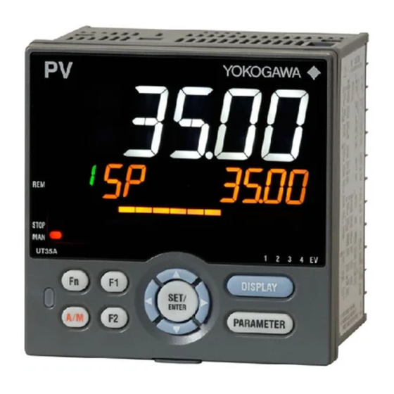
Page 3: Names And Functions Of Display Parts
UTAdvanced UT35A/UT32A Names and Functions of Display Parts UT35A Display Parts UT32A Display Parts Name Description No. in figure PV display Displays PV. Displays an error code if an error occurs. Displays the scrolling guide in the (white or red) Menu Display and Parameter Setting Display when the guide display ON/OFF is set to ON. - Page 4 UT35A Key Parts UT32A Key Parts Name Description No. in figure Used to switch the Operation Displays. UT35A: DISPLAY key Press the key in the Operation Display to switch the provided Operation Displays. UT32A: DISP key Press the key in the Menu Display or Parameter Setting Display to return to the Operation Display.
- Page 5 Brief Description of Parameter Map The parameter display level is a function to control the parameters to be displayed. The factory setting is LEVL=STD. The control prevents unintentional change of the function. The parameter display level is just a function to hide the display so the set function works. Changing of parameter display level The parameters to be displayed can be controlled by changing the setting value for setup parameter LEVL.
- Page 6 The following operating procedure describes an example of setting alarm setpoint (A1). <In case of UT35A> 1. Hold down the PARAMETER key for 3 seconds in the Operation Display to call up the [MODE] Menu Display. 2. Press the Right arrow key to display the [SP] Menu Display. 3.
- Page 7 How to Set Parameter Setpoint Numeric Value Setting Selection Data Setting Time (minute.second) Setting Page 7 / 18...
-
Page 8: List Of Display Symbols
List of Display Symbols The following shows the parameter symbols, menu symbols, alphanumeric of guide, and symbols which are displayed on the UT35A/UT32A. Figure (common to all display area) PV display (14 segments): Alphabet Symbol display and Data display (11 segments): Alphabet Group display (7 segments): Alphabet PV display (14 segments): Symbol Page 8 / 18... - Page 9 UTAdvanced UT35A/UT32A Operation Parameter Map * Some parameters are not displayed according to the model and suffix codes or the setting of CNT parameter. For details, refer to the User's Manual. Parameters for setting If you cannot remember how to carry out an operation during setting,...
-
Page 10: Setup Parameter Map
UTAdvanced UT35A/UT32A Setup Parameter Map * Some parameters are not displayed according to the model and suffix codes or the setting of CNT parameter. For details, refer to the User's Manual. Parameters for setting the basic functions of the Operation... - Page 11 UTAdvanced UT35A/UT32A List of Parameters * Some parameters are not displayed according to the model and suffix codes or the setting of CNT parameter. For details, refer to the User's Manual. Operation Parameters Operation Mode Menu Symbol Name Display level...
- Page 12 Group 1 Group 2 Group 3 Group 4 PID Setting (PIDN=1) (PIDN=2) (PIDN=3) (PIDN=4) Menu Symbol Name Display level Setting range Initial value User setting User setting User setting User setting Proportional band 0.0 to 999.9% Heating-side proportional band (in EASY When 0.0% is set, it operates as 0.1%.
-
Page 13: Setup Parameters
Setup Parameters Control Function Setting Menu Symbol Name Display level Setting range Initial value User setting PID: PID control ONOF: ON/OFF control (1 point of hysteresis) Standard type: PID Control type EASY ONOF2: ON/OFF control (2 points of hysteresis) Heating/cooling type: H/C 2P2L: Two-position two-level control H/C: Heating/cooling control 0: Standard PID control mode... - Page 14 Output Setting Menu Symbol Name Display level Setting range Initial value User setting Control output or Heating-side control output (Lower two digits) 00: OFF 01: OUT terminals (voltage pulse) 02: OUT terminals (current) 03: OUT terminals (relay/triac) 06: OUT2 terminals (relay) 07: RET/OUT2 terminals (voltage pulse) Standard type: 00.03 Output type selection...
- Page 15 PROFIBUS-DP Communication Setting Menu Symbol Name Display level Setting range Initial value User setting 9.6K: 9.6k bps 19.2K: 19.2k bps 93.75K: 93.75k bps 187.5K: 187.5k bps 0.5M: 0.5M bps PROF Baud rate EASY 1.5M: 1.5M bps AUTO 3M: 3M bps 6M: 6M bps 12M: 12M bps AUTO...
- Page 16 Display Function Setting Menu Symbol Name Display level Setting range Initial value User setting 0: Fixed in white 1: Fixed in red 2: Link to alarm 1 (Alarm OFF: white, Alarm ON: red) 3: Link to alarm 1 (Alarm OFF: red, Alarm ON: white) 4: Link to alarm 1 or 2 (Alarm OFF: white, Alarm ON: red) DISP PCMD...
- Page 17 Menu Lock Setting Menu Symbol Name Display level Setting range Initial value User setting MLOC [CTL] menu lock [PV] menu lock [MPV] menu lock [OUT] menu lock [HBA] menu lock R485 [R485] menu lock ETHR [ETHR] menu lock PROF [PROF] menu lock DNET [DNET] menu lock CC-L...
- Page 18 System Setting Menu Symbol Name Display level Setting range Initial value User setting CONT: Continue action set before power failure. R.MD Restart mode MAN: Start from MAN. CONT AUTO: Start from AUTO. R.TM Restart timer 0 to 10 s 0: Preset output Input error preset output 1: 0% output 2: 100% output...
Need help?
Do you have a question about the UTAdvanced UT35A and is the answer not in the manual?
Questions and answers