YOKOGAWA UT32A User Manual
Digital indicating controller
Hide thumbs
Also See for UT32A:
- Technical information (4 pages) ,
- User manual (178 pages) ,
- Operation manual (13 pages)

Related Manuals for YOKOGAWA UT32A


Summary of Contents for YOKOGAWA UT32A
- Page 1 User’s Manual UT32A Digital Indicating Controller (Entry Model) User’s Manual IM 05P01F31-01EN IM 05P01F31-01EN 2nd Edition...
- Page 2 Product Registration Thank you for purchasing YOKOGAWA products. YOKOGAWA provides registered users with a variety of information and services. Please allow us to serve you best by completing the product registration form accessible from our homepage. http://www.yokogawa.com/ns/reg/...
-
Page 4: Introduction
Introduction Thank you for purchasing the UT32A digital indicating controller (Entry model) (hereinafter referred to as UT32A). This manual describes how to use UT32A functions other than UT32A’s communication function. Please read through this user’s manual carefully before using the product. -
Page 5: Notice
Trademarks ● Our product names or brand names mentioned in this manual are the trademarks or registered trademarks of Yokogawa Electric Corporation (hereinafter referred to as YOKOGAWA). ● Microsoft, MS-DOS, Windows, Windows Vista, and Windows 7 are either registered trademarks or trademarks of Microsoft Corporation in the United States and/or other countries. - Page 6 • Be sure to use the spare parts approved by YOKOGAWA when replacing parts or consumables. • This product is not designed or manufactured to be used in critical applications that directly affect or threaten human lives.
-
Page 7: Handling Precautions For The Main Unit
• YOKOGAWA makes no warranties regarding the product except those stated in the WARRANTY that is provided separately. • The product is provided on an “as is” basis. YOKOGAWA assumes no liability to any person or entity for any loss or damage, direct or indirect, arising from the use of the product or from any unpredictable defect of the product. -
Page 8: Checking The Contents Of The Package
UT32A Main Unit The UT32A main units have nameplates affixed to the side of the case. Check the model and suffix codes inscribed on the nameplate to confirm that the product received is that which was ordered. -
Page 9: Model And Suffix Codes Of Ut32A (For Entry Model)
English, German, French, and Spanish are available for the guide display. When the /CT option is specified, the UT32A does not conform to the safety standards (UL and CSA) and CE marking (Products with /CT option are not intended for EEA-market). - Page 10 Affix the unit label to the front panel. If necessary, combine with unit prefixes. Affix it so that the LCD area is not blocked. • Affixing the unit label to the UT32A Affix the unit label over the letters “PV” on the front panel.
- Page 11 Suffix code Description X010 See the General Specifications (*) Resistance Module For UT32A • Brackets Part number L4502TP (2 pieces for fixing the upper and lower parts) • User’s Manual (A4 size) * User’s Manual can be downloaded from a website.
-
Page 12: Symbols Used In This Manual
Symbols Used in This Manual This symbol is used on the instrument. It indicates the possibility of injury to the user or damage to the instrument, and signifies that the user must refer to the user’s manual for special instructions. The same symbol is used in the user’s manual on pages that the user needs to refer to, together with the term “WARNING”... -
Page 13: How To Use This Manual
Chapters 1 to 18 as shown below. Chapter Title and Description Introduction to Functions Describes the main functions of the UT32A. UT32A Operating Procedures Describes the flow from unpacking to regular operations. Part Names Describes part names and functions on the front panel. -
Page 14: Table Of Contents
Safety Precautions ....................... ii Handling Precautions for the Main Unit ................iv Checking the Contents of the Package ................v Model and Suffix Codes of UT32A (for Entry model)............vi Symbols Used in This Manual ..................... ix How to Use This Manual ......................x Chapter 1 Introduction to Functions Quick Setting Function ..................... - Page 15 Contents Chapter 7 Input (PV) Functions Setting Functions of PV Input ................... 7-1 7.1.1 Setting Input Type, Unit, Range, Scale, and Decimal Point Position ....7-1 7.1.2 Setting Burnout Detection for Input ..............7-3 7.1.3 Setting Reference Junction Compensation (RJC) or External Reference Junction Compensation (ERJC) ................. 7-4 7.1.4 Correcting Input Value ..................
- Page 16 Contents Chapter 11 Alarm Functions 11.1 Setting Alarm Type ......................11-1 11.2 Setting Number of Alarm Groups to Use ...............11-12 11.3 Setting Hysteresis to Alarm Operation ................11-13 11.4 Delaying Alarm Output (Alarm Delay Timer) ..............11-14 11.5 Setting Alarm Action According to Operation Mode ............11-15 Chapter 12 Contact Output Functions 12.1 Contact Output Functions ....................
- Page 17 Contents Chapter 16 Troubleshooting, Maintenance, and Inspections 16.1 Troubleshooting ......................16-1 16.1.1 Troubleshooting Flowchart ................16-1 16.1.2 Errors at Power On ................... 16-2 16.1.3 Errors during Operation ..................16-4 16.2 Maintenance ......................... 16-13 16.2.1 Cleaning ......................16-13 16.2.2 Packaging when Shipping the Product for Repair .......... 16-13 16.2.3 Replacing Parts ....................
-
Page 18: Chapter 1 Introduction To Functions
Chapter 1 Introduction to Functions 1.1 Quick Setting Function The Quick setting function is a function to easily set the basic function of the controller. Check the contents. Buy and Unpacking Installation and Wiring: Chapter 17 Installation and Wiring Install and wire a controller, and then turn on the power. Q: What should I do to perform control immediately? Setup First, I want to set the input and output. -
Page 19: Input/Output Function
2 contact outputs can be incorporated. Contact output can output events such as alarms. 24 V DC Loop Power Supply 24 V DC loop power supply can be supplied to 2-wire transmitter. ► 17.4.10 24 V DC Loop Power Supply Wiring UT32A 2-wire transmitter IM 05P01F31-01EN... -
Page 20: Control Functions
1.3 Control Functions PID Control PID control is a general control using the PID control-related parameters. ► 8.2.1 PID Control Recorder UT32A Alarms Retransmission output 4-20 mA DC Electric furnace Thyristor IM 05P01F31-01EN... -
Page 21: Display And Key Functions
To intended use of the operator, the display level of the parameter can be set. ► Chapter 18 Parameters User Function Keys The UT32A has a user function key (Fn). Assign a function to a user function key to use it as an exclusive key. ► 13.2 Assigning Function to User Function Key and A/M Key... -
Page 22: Communication Functions
1.5 Communication Functions The UT32A can use RS-485 communication by specifying the suffix code and optional suffix code for each communication. ► UTAdvanced Series Communication Interface (RS-485, Ethernet) User’s Manual RS-485 Communication (Modbus communication, PC link communication, and Ladder communication) The UT32A can communicate with PCs, PLCs, touch panels, and other devices. - Page 23 Maintenance Port Communication (Power supply is not required for the UT32A) Maintenance port is used to connect with the dedicated cable when using LL50A Parameter Setting Software (sold separately). The parameters can be set without supplying power to the UT32A. LL50A Parameter Setting Software To USB terminal Dedicated cable CAUTION When using the maintenance port, do not supply power to the controller.
-
Page 24: Definition Of Main Symbols And Terms
1.6 Definition of Main Symbols and Terms Main Symbol PV: Measured input value SP: Target setpoint OUT: Control output value A/M: AUTO/MAN AUTO: Automatic MAN: Manual REMOTE, REM: Remote LOCAL, LCL: Local E1: Terminal areas ► 17.4 Wiring Engineering Units Input range (scale): the PV range low limit is set to 0%, and the high limit is set to 100% for conversion. - Page 25 Blank Page...
-
Page 26: Chapter 2 Ut32A Operating Procedures
Chapter 2 UT32A Operating Procedures 2.1 UT32A Operating Procedures Installation Install and wire a controller. and Wiring Installation and Wiring: Chapter 17 Power ON Control type setup Section 8.2 Control type setup Quick setting function: Input/output setup Chapter 5 Input setup Section 7.1 Output setup Set the other parameters as necessary. - Page 27 Blank Page...
-
Page 28: Chapter 3 Part Names
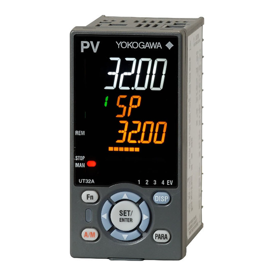
Chapter 3 Part Names 3.1 Names and Functions of Display Parts (1) PV display (2) Group display (8) Parameter display level indicator (3) Symbol display (4) Data display (9) Status indicator (5) Bar-graph display (6) Event indicator (10) Security indicator (7) Key navigation indicator (2) + (3) + (4) : Setpoint display No. in figure Name Description... -
Page 29: Names And Functions Of Keys
The setting is switched between AUTO and MAN each A/M key time the key is pressed. The user can assign a function key. The UT32A has Fn key. The user can assign a function to User function keys the key. The function is set by the parameter. IM 05P01F31-01EN... - Page 30 3.2 Names and Functions of Keys Maintenance Port (Power supply is not required for the UT32A). The maintenance port is used to connect with the dedicated cable when using LL50A Parameter Setting Software (sold separately). The parameters can be set without supplying power to the UT32A. Maintenance port Upper surface UT32A CAUTION When using the maintenance port, do not supply power to the controller. Otherwise, the controller does not work normally.
-
Page 31: List Of Display Symbols
3.3 List of Display Symbols The following shows the parameter symbols, menu symbols, alphanumeric of guide, and symbols which are displayed on the UT32A. Figure (common to all display area) PV display (14 segments): Alphabet Symbol display and Data display (11 segments): Alphabet (lower-case) IM 05P01F31-01EN... - Page 32 3.3 List of Display Symbols Group display (7 segments): Alphabet None PV display (14 segments): Symbol Space ‘ IM 05P01F31-01EN...
-
Page 33: Brief Description Of Setting Details (Parameters)
3.4 Brief Description of Setting Details (Parameters) This manual describes the Setting Details as follows in addition to the functional Description. Setting Details (Display Example) Parameter Display Name Setting range Menu symbol symbol level Set a display value of setpoint of PV alarm, SP alarm, deviation alarm, output alarm, or velocity Alarm-1 to -4 alarm. -
Page 34: Chapter 4 Basic Operation
Chapter 4 Basic Operation 4.1 Overview of Display Switch and Operation Keys The following shows the transition of Operation Display, Operation Parameter Setting Display, and Setup Parameter Setting Display. The “Operation Parameter Setting Display” has the parameters for setting the functions necessary for the operation. The “Setup Parameter Setting Display” has the parameters for setting the basic functions of the controller. - Page 35 4.1 Overview of Display Switch and Operation Keys The display pattern of the UT32A is as follows; the Menu Display and Parameter Setting Display. For the Operation Display, see Chapter 6, “Monitoring and Control of Regular Operations.” Display Description The Menu Display is segmented by the function and optional terminal position.
- Page 36 4.1 Overview of Display Switch and Operation Keys Display Shown at the End (the Lowest Level) of the Parameter Setting Display As shown in the figure below, the END Display is shown to indicate the end of the Menu Display and Parameter Setting Display. There are no setting items. The scrolling guide of END is displayed. END is displayed. Basic Key Operation Sequence ● To move to the Setup Parameter Setting Display Hold down the PARA key and the Left arrow key simultaneously for 3 seconds.
-
Page 37: How To Set Parameters
4.2 How to Set Parameters The following operating procedure describes an example of setting alarm setpoint (A1). Operation Hold down the PARA key for 3 seconds in the Operation Display to call up the [MODE] Menu Display. Press the Right arrow key to display the [SP] Menu Display. Press the SET/ENTER key to display the [SP] Parameter Setting Display. - Page 38 4.2 How to Set Parameters Press the SET/ENTER key to blink the setpoint. Press the Up or Down arrow key to change the setpoint. (Change the setpoint using the Up/Down arrow keys to increase and decrease the value and the Left/Right arrow keys to move between digits.) Press the SET/ENTER key to register the setpoint (the setpoint stops blinking).
- Page 39 4.2 How to Set Parameters How to Set Parameter Setpoint Numeric Value Setting Display the Parameter Setting Display. Press the SET/ENTER key to move to the setting mode (the setpoint blinks). Press the Left arrow key to move one digit to the left. (Press the Right arrow key to move one digit to the right.) Press the Up or Down arrow key to change the setpoint.
- Page 40 4.2 How to Set Parameters Time (minute.second) Setting Example of 17 minutes 59 seconds Display the Parameter Setting Display. Press the SET/ENTER key to move to the setting mode (the setpoint blinks). Press the Left arrow key to move one digit to the left. (press the Right arrow key to move one digit to the right.) Press the Up or Down arrow key to change the setpoint.
- Page 41 Blank Page...
-
Page 42: Chapter 5 Quick Setting Function
Chapter 5 Quick Setting Function 5.1 Setting Using Quick Setting Function Description The Quick setting function is a function to easily set the basic function of the controller. The Quick setting function starts when the power is turned on after wiring. The following lists the items to set using the Quick setting function. (1) Control type (PID control, ON/OFF control.) (2) Input function (PV input, range, scale (at voltage/current input), etc.) (3) Output function (cycle time) - Page 43 5.1 Setting Using Quick Setting Function Flowchart of Quick Setting Function Power ON Decide whether or not to use the Quick setting function. Press the UP arrow key to select YES. Press the SET/ENTER key to start the Quick setting function. Press the Down arrow key to select NO. Press the SET/ENTER key not to start the Quick setting function.
- Page 44 5.1 Setting Using Quick Setting Function Setting Example Set the following parameters to set to PID control, thermocouple Type K (range: 0.0 to 500.0ºC), and current control output. No need to change the parameters other than the following parameters. Set QSM = YES to enter the quick setting mode. (1) Set CNT = PID.
- Page 45 5.1 Setting Using Quick Setting Function Input Function Parameter Display Name Setting range Menu symbol symbol level OFF: Disable K1: -270.0 to 1370.0 ºC / -450.0 to 2500.0 ºF K2: -270.0 to 1000.0 ºC / -450.0 to 2300.0 ºF K3: -200.0 to 500.0 ºC / -200.0 to 1000.0 ºF J: -200.0 to 1200.0 ºC / -300.0 to 2300.0 ºF T1: -270.0 to 400.0 ºC / -450.0 to 750.0 ºF T2: 0.0 to 400.0 ºC / -200.0 to 750.0 ºF...
- Page 46 5.1 Setting Using Quick Setting Function Input Function (Continued) Parameter Display Name Setting range Menu symbol symbol level 0: No decimal place PV input scale 1: One decimal place decimal point EASY 2: Two decimal places position 3: Three decimal places 4: Four decimal places Maximum value of EASY PV input scale -19999 to 30000, (SL<SH),...
-
Page 47: Restarting Quick Setting Function
5.2 Restarting Quick Setting Function Once functions have been built using the Quick setting function, the Quick setting function does not start even when the power is turned on. The following methods can be used to restart the Quick setting function. ● Set the parameter QSM (Quick setting mode) to ON and turn on the power again. ●... -
Page 48: Chapter 6 Monitoring And Control Of Regular Operations
Chapter 6 Monitoring and Control of Regular Operations 6.1 Monitoring and Control of Operation Displays 6.1.1 Operation Display Transitions. ► Display/Non-display of Operation Display: 13.3.5 Setting Display/Non-display of Operation Display ► Registration of SELECT Display: 13.1.3 Registering SELECT Display (Up to 5 displays) SP Display (SP can be changed.) OUT Display (OUT can be changed in MAN mode.) Program Pattern Number Display (Display only) Parameter RMS = PROG PID Number Display (display only) - Page 49 6.1 Monitoring and Control of Operation Displays Details of the Operation Display The following is the Operation Display types and each display and operation description. PV display Setpoint display Operation Display Display and operation description PV display: Displays measured input value (PV). Setpoint display: Displays and changes target setpoint (SP). Target setpoint Symbol Target setpoint (SP) number...
- Page 50 6.1 Monitoring and Control of Operation Displays (Continued) Operation Display Display and operation description PV display: Displays measured input value (PV). Setpoint display: Displays control output value and changes control output value in MAN mode. Control output Symbol OUT Display Target setpoint (SP) number The Display is switched to the OUT Display if the operation mode is switched to MAN when other Operation Display is shown.
- Page 51 6.1 Monitoring and Control of Operation Displays (Continued) Operation Display Display and operation description PV display: Displays measured input value (PV). Setpoint display: Displays PV analog input value. PV analog input value Analog Input Symbol Display PV input Target setpoint (SP) number SELECT Display is for registering frequently-used parameters from Parameter Setting Display, and for displaying them on Operation Display so that the parameter settings can be easily changed in normal operation.
-
Page 52: Setting Target Setpoint
6.2 Setting Target Setpoint Operation in the Operation Display Operation Bring the SP Display into view. Press the SET/ENTER key to move to the setting mode (the setpoint blinks). Press the Left arrow key to move one digit to the left. (Press the Right arrow key to move one digit to the right.) Press the Up or Down arrow key to change a setpoint. - Page 53 6.2 Setting Target Setpoint Operation in Parameter Setting Display Setting Display Operation Display > PARA key for 3 seconds (to [MODE] Parameter Setting Display Menu Display) > Right arrow key (to [SP] Menu Display ) > SET/ENTER key (The setting parameter is displayed.) Press the Right arrow key until the [SP] Menu Display appears. In the Setting Display for the target setpoint parameter, pressing the Left or Right arrow keys changes the group.
-
Page 54: Performing And Canceling Auto-Tuning
6.3 Performing and Canceling Auto-tuning Setting Display Operation Display > PARA key for 3 seconds (to [MODE] Operation Mode Setting Display Menu Display) > SET/ENTER key (The operation mode is displayed.) > Down arrow key (The operation mode is displayed.) The parameter AT is displayed when the operation mode is AUTO. - Page 55 6.3 Performing and Canceling Auto-tuning Description Auto-tuning is a function with which the controller automatically measures the process characteristics and sets PID constants, which are control-related parameters, to optimum values for the setpoint. Auto-tuning temporarily executes ON/OFF control, calculates appropriate PID constants from response data obtained, and sets these constants. CAUTION Do not perform auto-tuning for the following processes.
- Page 56 6.3 Performing and Canceling Auto-tuning Tuning Point and Storage Location of Tuning Results The tuning point when performing auto-tuning is the target setpoint that is currently used for control computation. PID constants after the tuning are stored in the PID group that is specified when performing auto-tuning. Operation AT setpoint Tuning point Storage location mode Setpoint that is currently...
-
Page 57: Adjusting Pid Manually
6.4 Adjusting PID Manually Setting Display Operation Display > PARA key for 3 seconds (to [MODE] Parameter Setting Display Menu Display) > Right arrow key (to [PID] Menu Display ) > SET/ENTER key (The setting parameter is displayed.) > Down arrow key (The setting parameter is displayed.) In the Setting Display for the PID parameters, Displays can be arbitrarily switched using the Up, Down, Left or Right arrow key. - Page 58 6.4 Adjusting PID Manually Description Description and Tuning of Proportional Band The proportional band is defined as the amount of change in input (or deviation), as a percent of span, required to cause the control output to change from 0% to 100%. Because a narrower proportional band gives greater output change for any given deviation, it therefore also makes the control performance more susceptible to oscillation.
- Page 59 6.4 Adjusting PID Manually Description and Tuning of Integral Time The integral action (I action) is a function that will automatically diminish the offset (steady-state deviation) that is inherently unavoidable with proportional action alone. The integral action continuously increases or decreases the output in proportion to the time integral of the deviation (the product of the deviation and the time that the deviation continues.) The integral action is normally used together with proportional action as proportional- plus-integral action (PI action).
- Page 60 6.4 Adjusting PID Manually Description and Tuning of Derivative Time If the control object has a large time constant or dead time, the corrective action will be too slow with proportional action or proportional-plus-integral action alone, causing overshoot. However, even just sensing whether the deviation is on an increasing or a decreasing trend and adding some early corrective action can improve the controllability.
- Page 61 6.4 Adjusting PID Manually Manual PID Tuning Procedure (1) In principle, auto-tuning must be used. (2) Tune PID parameters in the order of P, I, and D. Adjust a numeric slowly by observing the result, and keep notes of what the progress is. (3) Gradually reduce P from a larger value.
-
Page 62: Setting Alarm Setpoint
6.5 Setting Alarm Setpoint Setting Display Operation Display > PARA key for 3 seconds (to [MODE] Parameter Setting Display Menu Display) > Right arrow key (to [SP] Menu Display) > SET/ENTER key (The setting parameter is displayed.) > Down arrow key (The setting parameter is displayed.) In the setting Display for the alarm parameters, Displays can be arbitrarily switched using the Up, Down, Left or Right arrow key. -
Page 63: Selecting Target Setpoint Number (Spno)
6.6 Selecting Target Setpoint Number (SPNO) Setting Display Operation Display > PARA key for 3 seconds (to [MODE] Parameter Setting Display Menu Display) > SET/ENTER key (The setting parameter is displayed.) > Down arrow key (The setting parameter is displayed.) Setting Details Parameter Display Name Setting range Menu symbol symbol... -
Page 64: Switching Operation Modes
6.7 Switching Operation Modes 6.7.1 Switching between AUTO and MAN Direct Operation by A/M Key Operation MAN lamp is lit in MAN mode. Each time you press the key, AUTO and MAN is switched alternately. Description AUTO/MAN switching can be performed by any of the following: (1) A/M key (2) Communication (3) User function key AUTO ►... - Page 65 6.7 Switching Operation Modes Operation Display in AUTO and MAN Modes “OUT” is displayed on Symbol display and “Output value” is displayed on Data display in MAN mode. (The OUT Display is shown.) SP Display is shown in AUTO mode. Lamp Status Status MAN lamp Automatic operation (AUTO) Unlit Manual operation (MAN)
-
Page 66: Switching Between Stop And Run
6.7 Switching Operation Modes 6.7.2 Switching between STOP and RUN Setting Display Operation Mode Setting Display Operation Display > PARA key for 3 seconds (to [MODE] Menu Display) > SET/ENTER key (The operation mode is displayed.) > Down arrow key (The operation mode is displayed.) Setting Details Parameter Display Name Setting range... - Page 67 6.7 Switching Operation Modes Operation Display in STOP and RUN Modes “STOP” is displayed on Symbol display and “Output value” is displayed on Data display in STOP mode. Preset output value is displayed. The display at operation start differs depending on AUTO or MAN mode. SP Display is shown in AUTO mode and OUT Display is shown in MAN mode.
-
Page 68: Switching Between Rem (Remote) And Lcl (Local)
6.7 Switching Operation Modes 6.7.3 Switching between REM (Remote) and LCL (Local) Setting Display Operation Mode Setting Display Operation Display > PARA key for 3 seconds (to [MODE] Menu Display) > SET/ENTER key (The operation mode is displayed.) > Down arrow key (The operation mode is displayed.) The parameter R.L is displayed when the the communication is specified. -
Page 69: Manipulating Control Output During Manual Operation
6.8 Manipulating Control Output during Manual Operation Operation Direct key method The value specified by the Up and Down arrow keys is output as is. Press the Up arrow key to increase the control output. Press the Down arrow key to decrease the control output. -
Page 70: Releasing On-State (Latch) Of Alarm Output
6.9 Releasing On-State (Latch) of Alarm Output Description Alarm latch can be released by any of the following. (1) User function key (2) Communication For the switching operation by using the above, the last switching operation is performed. Releasing the alarm latch function releases all of the latched alarm outputs. By factory default, the function is not assigned to the user function key. - Page 71 Blank Page...
-
Page 72: Chapter 7 Input (Pv) Functions
Chapter 7 Input (PV) Functions 7.1 Setting Functions of PV Input 7.1.1 Setting Input Type, Unit, Range, Scale, and Decimal Point Position Description The figure below describes the case of PV input. Example of Temperature Input The figure below is an example of setting Type K thermocouple and a measurement range of 0.0 to 800.0 ºC. -270.0°C 1370.0°C Input type Set a range to be PV input range controlled. - Page 73 7.1 Setting Functions of PV Input Setting Details Parameter Display Name Setting range Menu symbol symbol level OFF: Disable K1: -270.0 to 1370.0 ºC / -450.0 to 2500.0 ºF K2: -270.0 to 1000.0 ºC / -450.0 to 2300.0 ºF K3: -200.0 to 500.0 ºC / -200.0 to 1000.0 ºF J: -200.0 to 1200.0 ºC / -300.0 to 2300.0 ºF T1: -270.0 to 400.0 ºC / -450.0 to 750.0 ºF T2: 0.0 to 400.0 ºC / -200.0 to 750.0 ºF...
-
Page 74: Setting Burnout Detection For Input
7.1 Setting Functions of PV Input (Continued) Parameter Display Name Setting range Menu symbol symbol level 0: No decimal place 1: One decimal place PV input scale decimal EASY 2: Two decimal places (Scaling) point position 3: Three decimal places 4: Four decimal places Maximum value of PV -19999 to 30000, (SL<SH), EASY (Scaling) -
Page 75: Setting Reference Junction Compensation (Rjc) Or External Reference
RJC function of the controller can be turned off. External Reference Junction Compensation (ERJC) For TC input, a temperature compensation value for external device can be set. The external RJC can be used only when RJC = OFF. UT32A Terminal block Compensating lead wire Furnace UT32A... -
Page 76: Correcting Input Value
7.1 Setting Functions of PV Input 7.1.4 Correcting Input Value (1) Setting Bias and Filter Description PV Input Bias The PV input bias allows bias to be summed with input to develop a measured value for display and control use inside the controller. This function can also be used for fine adjustment to compensate for small inter- instrument differences in measurement reading that can occur even if all are within the specified instrument accuracies. - Page 77 7.1 Setting Functions of PV Input Setting Details Parameter Display Name Setting range Menu symbol symbol level -100.0 to 100.0% of PV PV input bias EASY input range span (EUS) PV input filter EASY OFF, 1 to 120 s Parameter Display Name Setting range Menu symbol symbol level -100.0 to 100.0% of each A.BS...
-
Page 78: Chapter 8 Control Functions
Chapter 8 Control Functions 8.1 Control Function Block Diagrams 8.1.1 Single-loop Control Description These control functions provide the basic control function having one control computation unit. Single-loop control can be used for Standard type controller. ► PID control: 8.2 Setting Control Type (CNT) The Function block diagram describes only the basic functions. Parameter symbols in the Function block diagram describe representative parameters. - Page 79 8.1 Control Function Block Diagrams n Single-loop Control Function Block Diagram Equipped as standard PV input Input type Input unit UNIT Input range/scale RH, RL SH, SL Communication PV input bias SPNO PV input filter Ratio bias computation Target setpoints 1 to 4 REMOTE LOCAL SP limiter SPH, SPL SP ramp rate UPR, DNR PV display...
-
Page 80: Setting Control Type (Cnt)
8.2 Setting Control Type (CNT) The following table shows combination of Standard type. Suffix code: Type 1 Control type Standard type PID control √ ON/OFF control √ (1 point of hysteresis) ON/OFF control √ (2 points of hysteresis) √: Available, N/A: Not available The following table shows combination of control type (CNT) and output type. Output type Control type Time proportional... -
Page 81: Pid Control
8.2 Setting Control Type (CNT) 8.2.1 PID Control Description PID control is a general control using control-related parameters PID. When PID control is selected, PID should be obtained by auto-tuning after setting SP or PID should be set manually. Setting Details Parameter Display Name Setting range Menu symbol symbol level... -
Page 82: On/Off Control (1 Point Of Hysteresis / 2 Points Of Hysteresis)
8.2 Setting Control Type (CNT) 8.2.2 ON/OFF Control (1 point of hysteresis / 2 points of hysteresis) Description ON/OFF control compares the SP and PV and outputs an on or off signal according to the positive or negative deviation (PV – SP). Hysteresis can be set in the vicinity of the on/off output operating point. If the SP and PV become close and the polarity of the deviation reverses frequently, the on/off output will cycle repeatedly. - Page 83 8.2 Setting Control Type (CNT) Setting Details Parameter Display Name Setting range Menu symbol symbol level PID: PID control ONOF: ON/OFF control (1 point of Control type EASY hysteresis) ONOF2: ON/OFF control (2 points of hysteresis) In ON/OFF control: 0.0 to 100.0% Hysteresis EASY of PV input range span (EUS) Upper-side HY.UP hysteresis (in ON/...
-
Page 84: Pd Control (Stable Control In Which A Setpoint Is Not Exceeded)
8.2 Setting Control Type (CNT) 8.2.3 PD Control (Stable Control in Which a Setpoint is not Exceeded) Description This control type performs control in which integral action (I action) is excluded from PID action. Set the integral time (I or Ic) to OFF. It is useful when stable control in which a setpoint is not exceeded is desired for integral processes in which constant flows are delivered. -
Page 85: Setting Pid Control Mode (Alg)
8.3 Setting PID Control Mode (ALG) Description There are two PID control modes: standard PID control mode and fixed-point control mode. Select a PID control computation formula shown in the following table according to the control mode or operation mode. Operation mode AUTO+Local AUTO+Remote Standard PID control PV derivative type Deviation derivative type mode... - Page 86 8.3 Setting PID Control Mode (ALG) Deviation Derivative Type PID The PID control method in which derivative action works for the deviation value = PV – The following shows the deviation derivative type PID control computation formula. ∫ = 100 • • where OUT: control output, e: deviation (PV-SP), P: proportional band, Ti: integral time, and Td: derivative time Setting Details...
-
Page 87: Switching Pid
8.4 Switching PID 8.4.1 Switching PID According to Target Setpoint Number (SPNO) Description The SP group number selection selects a group of target setpoint (SP) and PID parameters by switching the SP number (SPNO). The PID number selection (PIDN) can be set for each SP group. SP number (SPNO) PID parameter group SP of group 1 Specify using the parameter PIDN of group 1 SP of group 2... -
Page 88: Switching Pid According To Pv
8.4 Switching PID 8.4.2 Switching PID According to PV Description The PID switching according to PV is a function that switches between the groups of PID parameters according to the PV. The maximum number of PID groups to be switched is 8. (Set RP1 to RP3.) This function is useful for reactors in which the chemical reaction gain changes depending on the temperature. - Page 89 8.4 Switching PID Setting Details Parameter Display Name Setting range Menu symbol symbol level 0: SP group number selection 1 1: Zone PID selection (selection by PV) Zone PID 2: Zone PID selection (selection selection by target SP) 3: SP group number selection 2 4: Zone PID selection (selection by SP) 0.0 to 100.0% of PV input range...
-
Page 90: Switching Pid According To Sp
8.4 Switching PID 8.4.3 Switching PID According to SP Description The zone PID selection by SP switches between the groups of PID parameters according to the SP. The maximum number of PID groups to be switched is 4. (Set RP1 to RP3) The figure below shows the example of switching the group of PID parameters according to the SP. - Page 91 8.4 Switching PID Setting Details Parameter Display Name Setting range Menu symbol symbol level 0: SP group number selection 1 1: Zone PID selection (selection by PV) Zone PID 2: Zone PID selection (selection selection by target SP) 3: SP group number selection 2 4: Zone PID selection (selection by SP) 0.0 to 100.0% of PV input range...
-
Page 92: Switching Pid According To Target Sp
8.4 Switching PID 8.4.4 Switching PID According to Target SP Description The zone PID selection by target SP switches between the groups of PID parameters according to the target SP. The figure below shows the example of switching the group of PID parameters according to the target SP. It shows an example of dividing the PV input range from the maximum value to the minimum value into four zones by reference points 1 to 3. - Page 93 8.4 Switching PID Setting Details Parameter Display Name Setting range Menu symbol symbol level 0: SP group number selection 1 1: Zone PID selection (selection by PV) Zone PID 2: Zone PID selection (selection selection by target SP) 3: SP group number selection 2 4: Zone PID selection (selection by SP) 0.0 to 100.0% of PV input range...
-
Page 94: Switching Pid According To Deviation (Reference Deviation)
8.4 Switching PID 8.4.5 Switching PID According to Deviation (Reference Deviation) Description The zone PID selection by deviation switches between the groups of PID parameters according to the amount of deviation. This function is called “reference deviation.” In the fixed point control, if the actual amount of deviation exceeds the setpoint of the reference deviation, the controller automatically changes to the PID parameter group (PID of group R) set for the zone. -
Page 95: Setting Hysteresis At Time Of Pid Switch
8.4 Switching PID 8.4.6 Setting Hysteresis at Time of PID Switch Description When the zone PID selection is selected, hysteresis at time of each zone switch can be set. The following shows the operation example of hysteresis at time of zone switch. Reference point 1 Hysteresis 0.5% of PV input range span PID of group 1 PID of group 2 PID of group 1... -
Page 96: Suppressing Overshoot (Super Function)
8.5 Suppressing Overshoot (Super Function) Description The Super function monitors the deviation for evidence that there is a danger of overshoot, and on sensing such danger automatically changes the setpoint temporarily to a somewhat lower value (sub-SP). Once the danger of overshoot appears diminished, the function returns the effective SP gradually to the true SP. - Page 97 8.5 Suppressing Overshoot (Super Function) Example of Overshoot Suppression Control for Setpoint Changes Time Time SUPER is not used SUPER is used Example of Overshoot Suppression Control for Ramp-to-soak Transition Sub-SP Time Time SUPER is not used SUPER is used Setting Details Parameter Display Name Setting range Menu symbol symbol level OFF: Disable 1: Overshoot suppressing function (normal mode) 2: Hunting suppressing function Super function EASY...
-
Page 98: Suppressing Hunting (Super2 Function)
8.6 Suppressing Hunting (Super2 Function) Description The Super2 function suppresses the hunting effect of the controller without re-tuning the PID parameters. Hunting means the PV becomes unstable and oscillates around SP. SUPER2 = ON Hunting ● In hunting condition, the Super2 function selects the output from process model as PV signal. - Page 99 8.6 Suppressing Hunting (Super2 Function) Setting Details Parameter Display Name Setting range Menu symbol symbol level OFF: Disable 1: Overshoot suppressing function (normal mode) 2: Hunting suppressing function Super function EASY (stable mode) TUNE 3: Hunting suppressing function (response mode) 4: Overshoot suppressing function (strong suppressing mode). Set SC=2 when there are a lot of disturbances, and much hunting occurs.
-
Page 100: Suppressing Integral Action (Anti-Reset Wind-Up)
8.7 Suppressing Integral Action (Anti-reset Wind-up) Description Where there is a large deviation at the start of the control operation, for example, integral outputs are accumulated and the PV exceeds the SP, thereby causing the output to overshoot. To avoid this, the controller provides an anti-reset wind-up function for suppressing an extreme integral output by stopping PID computations. -
Page 101: Adjusting Auto-Tuning Operation
8.8 Adjusting Auto-tuning Operation Description Auto-tuning Type “Normal” of auto-tuning type requires a rapidly rising PID constant. This type is useful for processes that allow some overshooting. On the other hand, “stable” of auto-tuning type requires a slowly rising PID constant. Auto-tuning Output Limiter When executing auto-tuning, the control output high and low limits can be set. -
Page 102: Chapter 9 Auxiliary Control Functions
Chapter 9 Auxiliary Control Functions 9.1 Setting SP Limiter Description The SP high and low limits can be set to restrict the SP to the range between those limits whether in REM (remote) or LCL (local) mode. They works to the SP of all SP groups. 100.0 High limit of SP Setting range of actual SP... -
Page 103: Changing Sp At A Fixed Rate (Sp Ramp-Rate Setting Function)
9.2 Changing SP at a Fixed Rate (SP Ramp-Rate Setting Function) Description SP ramp-rate setting function forces SP to change at a fixed rate when SP is changed in order to prevent abrupt changes in SP. Velocity (rate-of-change) can be set for both the SP ramp-up rate (UPR) and SP ramp- down rate (DNR). - Page 104 9.2 Changing SP at a Fixed Rate (SP Ramp-Rate Setting Function) SP switch SP of group 1 SP of group 2 SP of group 2= 640ºC Temperature difference of 140ºC 70ºC/min UPR = 140/2 = 70 (ºC/min) SP of group 1 = 500ºC Temperature rise time of 2 min. Temperature difference (ºC) 140ºC UPR = = 70 (ºC/min)
-
Page 105: Forcing Sp To Track Pv (Pv Tracking)
9.3 Forcing SP to Track PV (PV Tracking) Description PV tracking function is used to prevent abrupt PV changes. With PV tracking, SP is first aligned with PV and then changed to its original SP at the SP ramp rate. ► SP ramp-rate setting function: 9.2 Changing SP at a Fixed Rate (SP Ramp-Rate Setting Function) PV tracking function works when: (1) Power is turned on or has recovered from a failure,... -
Page 106: Forcing Sp To Track Remote Input (Sp Tracking)
9.4 Forcing SP to Track Remote Input (SP Tracking) Description SP tracking function is the function to force the local setpoint (SP) to track the remote setpoint (RSP) when the operation mode is switched from REM (remote) to LCL (local) mode. The function is effective to prevent abrupt PV changes. SP tracking enabled SP tracking disabled Time... -
Page 107: Setting Controller Action At Power On (Restart Mode)
9.5 Setting Controller Action at Power ON (Restart Mode) Description For details, see Chapter 15, “Power Failure Recovery Processing.” Setting Details Parameter Display Name Setting range Menu symbol symbol level Set how the controller should recover from a power failure of 5 seconds or more. R.MD Restart Mode CONT: Continue action set before power failure. -
Page 108: Setting Time Between Powering On Controller And Starting Control (Restart Timer)
9.6 Setting Time between Powering on Controller and Starting Control (Restart Timer) Description The time between power on and the instant where controller starts control computation can be set. Operation start time = Operating time of controller initialization after power on. Setting Details Parameter Display Name Setting range Menu symbol symbol level R.TM... - Page 109 Blank Page...
-
Page 110: Chapter 10 Control Output Functions
The pulse width is calculated as follows with the cycle time (control output cycle) at 100%. Control output pulse width = Control output (%) x Cycle time The output type is selected as either the relay output or the voltage pulse output. UT32A Ristricted to the range ON/OFF signal between output high... -
Page 111: Setting Control Output Cycle Time
10.2 Setting Control Output Cycle Time Description Cycle time is the basic cycle period for a signal full cycle of ON/OFF operation for a relay or voltage pulse output. Reducing cycle time results in faster cycling and finer control. In contrast, reducing the ON/OFF period also reduces relay life. For relay output, set the control output cycle time to 30 to 200 seconds according to the process speed. -
Page 112: Setting Limiter To Control Output
10.3 Setting Limiter to Control Output Description Control output high and low limits can be set to restrict the control output to the operation range between those limits. The output limiter is prepared for each PID group, and works according to the selected PID group. This, however, excludes preset output in STOP mode. -
Page 113: Disabling Output Limiter In Man Mode
10.4 Disabling Output Limiter in MAN mode Description Output limiter can be released when in MAN mode. Note that the output bump is caused if the operation mode is changed from MAN to AUTO while the control output is out of the range between the control output high limit (OH) and control output low limit (OL). -
Page 114: Setting Velocity Limiter To Control Output
10.5 Setting Velocity Limiter to Control Output Description Output velocity limiter prevents the control output signal from changing suddenly in order to protect the control valves (or other actuators) and controlled process. The output velocity limiter does not work in MAN or STOP mode or when input burnout or A/D error occurs. -
Page 115: Reducing 4-20 Ma Current Output To 0 Ma (Tight Shut Function)
10.6 Reducing 4-20 mA Current Output to 0 mA (Tight Shut Function) Description Tight shut function fully closes the control valve (or other actuators) (i.e., so that output is zero) beyond its positioner dead band. When the output low limit is set to “SD,” the output is as follows in MAN or AUTO mode. • In MAN mode When the output is reduced with the Down arrow key and “SD”... -
Page 116: Setting On/Off Control Hysteresis
10.7 Setting ON/OFF Control Hysteresis Description In ON/OFF control, since the only two possible output states are ON and OFF, the control output cycles are as shown in the figure below. ON/OFF becomes quite narrow, so that if relay output is used, chattering occurs. In this case, the hysteresis should be set wider to prevent relay chattering and for the service life of the relay. - Page 117 10.7 Setting ON/OFF Control Hysteresis Setting Details Parameter Display Name Setting range Menu symbol symbol level In ON/OFF control: 0.0 to Hysteresis (in ON/OFF EASY 100.0% of PV input range control) span (EUS) Upper-side hysteresis HY.UP EASY (in ON/OFF control) 0.0 to 100.0% of PV input Lower-side hysteresis range span (EUS) HY.LO...
-
Page 118: Canceling Offset Of Pv And Sp (Manual Reset)
10.8 Canceling Offset of PV and SP (Manual Reset) Description Manual reset can be used when the integral action is disabled. When the integral action is disabled, there will be an offset of PV and SP. Manual reset cancels this offset. The manual reset value equals the output value when PV = SP is true. Setting Details Parameter Display... -
Page 119: Setting Preset Output Value
10.9 Setting Preset Output Value 10.9.1 Setting Output Value in STOP Mode (Preset Output) Description Preset output becomes the output when the operation mode is switched from RUN to STOP. The preset output is not limited by the output high and low limits. The preset output is prepared for each PID parameter group, and works according to the selected PID parameter group. -
Page 120: Setting Output Value When Switched To Man Mode (Manual Preset Output)
10.9 Setting Preset Output Value 10.9.2 Setting Output Value When Switched to MAN Mode (Manual Preset Output) Description When the operation mode is switched from AUTO to MAN, each of the following can be selected. • The control output takes over the control output as is. • The control output bumps to the manual preset output. When the manual preset output is output, the manual operation is possible after the bump. -
Page 121: Setting Output Value When Error Occurs (Input Error Preset Output)
10.9 Setting Preset Output Value 10.9.3 Setting Output Value When Error Occurs (Input Error Preset Output) Description The 0% control output, 100% control output, or input preset output can be selected and output as input error preset output in the following conditions. • The input burnout occurs during operation in AUTO mode and RUN mode. •... -
Page 122: Changing Current Output Range
10.10 Changing Current Output Range Description The analog output type can be selected from among 4 to 20, 0 to 20, 20 to 4, or 20 to 0 Setting Details Parameter Display Name Setting range Menu symbol symbol level 4-20: 4 to 20 mA, OUT current output 0-20: 0 to 20 mA, OU.A range... - Page 123 Blank Page...
-
Page 124: Chapter 11 Alarm Functions
Chapter 11 Alarm Functions 11.1 Setting Alarm Type Description The alarm-related parameters consist of the alarm type (type, stand-by action, energized/ de-energized, and latch function), PV velocity alarm time setpoint, alarm hysteresis, alarm (On-/Off-) delay timer, and alarm setpoint. Alarm-related parameter Number of settings Alarm type 4 (number of settings) PV velocity alarm time setpoint 4 (number of settings) Alarm hysteresis 4 (number of settings) - Page 125 11.1 Setting Alarm Type PV High Limit Alarm and PV Low Limit Alarm PV high limit alarm output PV high limit Alarm hysteresis alarm setpoint Alarm hysteresis PV low limit alarm setpoint PV low limit alarm output Time Contact type in the figure above: Energized when an event occurs (factory default). SP High Limit Alarm and SP Low Limit Alarm SP high limit alarm output...
- Page 126 11.1 Setting Alarm Type Deviation High Limit Alarm and Deviation Low Limit Alarm Deviation high limit alarm output Alarm hysteresis Deviation high limit alarm setpoint (positive setpoint) Target setpoint (SP) Deviation low limit alarm setpoint (negative setpoint) Alarm hysteresis Deviation low limit alarm output Time Contact type in the figure above: Energized when an event occurs (factory default). When a negative setpoint is set for the deviation high limit alarm setpoint, the deviation setpoint will be lower than the SP.
- Page 127 11.1 Setting Alarm Type Target SP High Limit Alarm and Target SP Low Limit Alarm Target SP high limit alarm output Alarm hysteresis Target SP high limit alarm setpoint SP in ramp rate setting Taraget SP Target SP low limit alarm setpoint Alarm hysteresis Target SP low limit alarm output Time SP changing SP changing SP changing SP changing...
- Page 128 11.1 Setting Alarm Type Target SP Deviation High and Low Limits Alarm Deviation high and low limits alarm output Alarm hysteresis Deviation high and low limits alarm setpoint Target SP (SP) Alarm hysteresis Time Contact type in the figure above: Energized when an event occurs (factory default). Target SP Deviation within High and Low Limits Alarm Deviation within high and low limits alarm output Alarm hysteresis...
- Page 129 11.1 Setting Alarm Type Control Output High Limit Alarm and Control Output Low Limit Alarm Control output high limit alarm output Control output high limit Alarm hysteresis alarm setpoint Control output (OUT) Alarm hysteresis Control output low limit alarm setpoint Control output low limit alarm output Time Contact type in the figure above: Energized when an event occurs (factory default). Analog Input PV High Limit Alarm and Analog Input PV Low Limit Alarm These alarms monitor the input value after the analog input computation process (entrance to the input ladder calculation) is completed.
- Page 130 11.1 Setting Alarm Type PV Velocity Alarm PV velocity alarm output Exceeds the velocity Monitors the variation of the measured value for 2 points by the time interval set in VT. Time Velocity alarm Velocity alarm setpoint setpoint Velocity alarm Velocity alarm An alarm occurs if the velocity time setpoint time setpoint exceeds this inclination.
- Page 131 11.1 Setting Alarm Type Stand-by Action The stand-by action is a function for ignoring the alarm condition and keeps the alarm off until the alarm condition is removed. Once the alarm condition is removed, the stand-by action is cancelled. It is effective in the following cases where; •...
- Page 132 11.1 Setting Alarm Type Alarm Latch Function The alarm latch function is a function for keeping the alarm output (keeping the alarm output on) after entering the alarm condition (alarm output is turned on) until an order to release the alarm latch is received. The alarm latch function has the following four types of action. Latch 1 Cancels the alarm output when an order to release the alarm latch is received.
- Page 133 11.1 Setting Alarm Type Release of Alarm Latch The alarm latch function can be cancelled by the user function key, via communication. Cancelling the alarm latch function cancels all latched alarm outputs. ► Release by user function key: 13.2 Assigning Function to User Function Key and A/M key ►...
- Page 134 11.1 Setting Alarm Type Setting Details Parameter Display Name Setting range Menu symbol symbol level AL1 to AL4 Alarm-1 to -4 type EASY See the table below. ALRM PV velocity alarm time 00.01 to 99.59 VT1 to VT4 EASY setpoint 1 to 4 (minute.second) Note1: The initial values of the parmeters AL1 to AL4 and VT1 to VT4 are "4".
-
Page 135: Setting Number Of Alarm Groups To Use
11.2 Setting Number of Alarm Groups to Use Description Up to four alarm groups of alarm type, alarm hysteresis, alarm (On-/Off-) delay timer, and alarm setpoint are available. Unused alarm parameters can be hidden and their functions can be turned off. The initial value of parameter ALNO. is “4.” When ALNO. -
Page 136: Setting Hysteresis To Alarm Operation
11.3 Setting Hysteresis to Alarm Operation Description If the On/Off switch of the alarm output is too busy, you can alleviate the busyness by increasing the alarm hysteresis. Hysteresis for PV High Limit Alarm Point of ON/OFF action Output (alarm setpoint) Hysteresis When Setting Hysteresis of 5ºC and 15ºC for PV High Limit Alarm HYS: 5ºC (example) HYS: 15ºC (example) Closed (ON) Closed (ON) Open... -
Page 137: Delaying Alarm Output (Alarm Delay Timer)
11.4 Delaying Alarm Output (Alarm Delay Timer) Description The alarm on-delay timer is a function for turning on the alarm when the alarm condition occurs, and the timer starts and the set time elapses. The timer is reset if the alarm condition is removed while the timer is running. No alarm is generated. -
Page 138: Setting Alarm Action According To Operation Mode
11.5 Setting Alarm Action According to Operation Mode Description The alarm action usually functions regardless of operation modes. Setting the alarm mode allows the alarm action to be disabled in STOP or in STOP or MAN mode. Setting Details Parameter Display Name Setting range Menu symbol symbol level 0: Always active... - Page 139 Blank Page...
-
Page 140: Chapter 12 Contact Output Functions
Chapter 12 Contact Output Functions 12.1 Contact Output Functions 12.1.1 Setting Function of Contact Output Description The contact output function works by setting a status such as an alarm to the contact output. This explanation assumes that the contact type is energized. (The contact is turned on when an event occurs.) Setting Details Contact Output Equipped as Standard Parameter... - Page 141 12.1 Setting Contact Input Function Alarm Latch Status The alarm latch status can be output to another contact output irrespective of the setting of alarm-1 to -4 type (AL1 to AL4). (The setpoints below are I relay numbers.) ► I relay: UTAdvanced Series Communication Interface (RS-485, Ethernet) User's Manual Setpoint Function Alarm output...
- Page 142 12.1 Setting Contact Input Function System Error Status Contact status Setpoint Function 4769 Message display interruption 1 status With interruption Without interruption 4770 Message display interruption 2 status With interruption Without interruption 4771 Message display interruption 3 status With interruption Without interruption 4773 Message display interruption 4 status With interruption Without interruption Error Status...
-
Page 143: Changing Contact Type Of Contact Output
12.1 Setting Contact Input Function 12.1.2 Changing Contact Type of Contact Output Description The contact type can set the action direction of contact output assigned to the function. Setting Details Contact Output Equipped as Standard Parameter Display Name Setting range Menu symbol symbol level 0: When the event of assigned AL1.D AL1 contact type function occurs, the contact output is closed. -
Page 144: Chapter 13 Display, Key, And Security Functions
Chapter 13 Display, Key, and Security Functions 13.1 Setting Display Functions 13.1.1 Setting Active Color PV Display Function The active color PV display function changes the PV display color when an event occurs. Description Link to Alarm The PV display color changes by linking to the alarm 1 or alarm 2. The following is an example of operation linking to alarm 1. Set the alarm-1 type to “PV high limit alarm”... - Page 145 13.1 Setting Display Functions Link to PV The PV display color changes by linking to PV. Set the PV color change high limit to “70°C” and the PV color change low limit to “20°C.” PV display color changes from white to red if PV is out of the range. The red-to-white switching action can be set.
- Page 146 13.1 Setting Display Functions Setting Details Parameter Display Name Setting range Menu symbol symbol level 0: Fixed in white 1: Fixed in red 2: Link to alarm 1 (Alarm OFF: white, Alarm ON: red) 3: Link to alarm 1 (Alarm OFF: red, Alarm ON: white) 4: Link to alarm 1 or 2 (Alarm OFF: white, Alarm ON: red) Active color PV...
-
Page 147: Masking Arbitrary Display Value In Operation Display
13.1 Setting Display Functions 13.1.2 Masking Arbitrary Display Value in Operation Display Description Display/non-display of the PV display, Setpoint display, and Status display in the Operation Display can be set. Items that you do not want to display can be set to non-display. For example, when the Setpoint display is set to non-display, SP of the SP Display and OUT of the OUT Display are not displayed. -
Page 148: Registering Select Display (Up To 5 Displays)
13.1 Setting Display Functions 13.1.3 Registering SELECT Display (Up to 5 Displays) Description Registering frequently changed-operation parameters (except for the operation mode) in the SELECT Display of the Operation Displays will allow you to change parameter settings easily. A maximum of five Displays can be registered. Set the D register number of the parameter you wish to register for the registration to the SELECT Display. -
Page 149: Changing Event Display
13.1 Setting Display Functions 13.1.4 Changing Event Display Description The UT32A has four event (EV) lamps. The alarms 1 to 4 are assigned to EV1 to EV4. Setting Details Parameter Display Menu Name Setting range symbol level symbol Setting range: 4001 to 6304 OFF: Disable... -
Page 150: Registering Select Parameter Display (Up To 10 Displays)
13.1 Setting Display Functions 13.1.5 Registering SELECT Parameter Display (Up to 10 Displays) Description Registering frequently changed operation parameters (change frequency is lower than SELECT Display) in the SELECT Parameter Display will allow you to change parameter settings easily. A maximum of ten Displays can be registered. Set the D register number of the parameter you wish to register for the registration to the SELECT Parameter Display. - Page 151 13.1 Setting Display Functions Setting Details Parameter Display Name Setting range Menu symbol symbol level OFF: No registration CS10 to SELECT parameter-10 D register number (2301 to CSEL CS19 to -19 registration 5000) For D register numbers, see sections 8.4.2 and 8.4.5 of UTAdvanced Series Communication Interface User’s Manual.
-
Page 152: Setting Bar-Graph Display Function
13.1 Setting Display Functions 13.1.6 Setting Bar-graph Display Function Description The bar-graph display is provided on the front of the controller. PV or OUT can be displayed. Data which can be displayed on Bar-graph display are as follows. OUT, Output Displayed by 10% increment of output 100% Less than 0% More than 100% For relay, OFF is equivalent to 0% and ON is equivalent to 100%. - Page 153 13.1 Setting Display Functions Setting Details Parameter Display Name Setting range Menu symbol symbol level 0: Disable 1:OUT 3: PV 4: SP Bar-graph display BAR1 5: Deviation registration 6 to 16: Disable DISP 18: PV terminals analog input 27: TSP 28: Deviation between the TSP Bar-graph 0.0 to 100.0% of PV input range deviation display...
-
Page 154: Masking Least Significant Digit Of Pv Display
13.1 Setting Display Functions 13.1.7 Masking Least Significant Digit of PV Display Description With and without least significant digit of the PV in the Operation Display can be set. When without least significant digit is set, the value of the least significant digit is truncated and not displayed. The internal value is not changed depending on whether with or without least significant digit (the value is for display only). -
Page 155: Setting Economy Mode
13.1 Setting Display Functions 13.1.8 Setting Economy Mode Description The LCD backlight ON/OFF can be set in the following methods. Setting the LCD backlight to OFF saves energy. User Function Keys The LCD backlight ON/OFF switch can be assigned to the user function key. ► User function key: 13.2 Assigning Function to User Function Key and A/M Key Backlight OFF timer The backlight OFF timer sets the economy mode parameter to ON. -
Page 156: Switching Guide Display Language
13.1 Setting Display Functions 13.1.10 Switching Guide Display Language Description The guide display language that appears when the parameter or the menu is displayed can be switched. Setting Details Parameter Display Name Setting range Menu symbol symbol level ENG: English Guide display FRA: French LANG EASY language GER: German SPA: Spanish 13.1.11... -
Page 157: Setting Automatic Return To Operation Display
13.1 Setting Display Functions 13.1.13 Setting Automatic Return to Operation Display Description The Display will automatically revert to the Operation Display if no keys are pressed for 5 minutes in Menu Display or Parameter Setting Display. Setting Details Parameter Display Name Setting range Menu symbol symbol level ON: Automatically returned to the Operation Display. -
Page 158: Assigning Function To User Function Key And A/M Key
13.2 Assigning Function to User Function Key and A/M Key Description The UT32A has one user function key on the front panel. Various functions (operation mode switch etc.) can be assigned to the user function key. Press the user function key to perform the assigned function. The User function key is available only on the Operation Display. - Page 159 13.2 Assigning Function to User Function Key and A/M Key Setting Details Parameter Display Name Setting range Menu symbol symbol level User function key action setting EASY See the table below A/M key action setting Availability (Note 1) Setpoint Function Action Unassigned – √ √ √ √ AUTO and MAN switches every time the user AUTO/MAN switch √...
- Page 160 13.2 Assigning Function to User Function Key and A/M Key Status of user function key The status of the user function key can be identified by communication. “1” can be read while the user function key is held down, and “0” can be read when the user function key is released. (Initial value: 0) ►...
-
Page 161: Setting Security Functions
13.3 Setting Security Functions 13.3.1 Setting/canceling a Password Description The password function can prevent inadvertent changes to the parameter settings. If a password is set, the checking is required when moving to the Setup Parameter Setting Display. When the password is verified, can be changed to the Setup Parameter Setting Display. -
Page 162: Locking (Hiding) Parameter Menu Display
13.3 Setting Security Functions 13.3.3 Locking (Hiding) Parameter Menu Display Description The parameter menu display lock function hides the following Parameter Menu Displays. Setting Details Parameter Display Name Setting range Menu symbol symbol level [CTL] menu lock [PV] menu lock [MPV] menu lock [OUT] menu lock R485 [R485] menu lock [KEY] menu lock DISP [DISP] menu lock... -
Page 163: Key Lock
13.3 Setting Security Functions 13.3.4 Key Lock Description The key lock function locks the key on the front panel to prohibit key operation. It can prohibit the operation mode switch or parameter setting change. Setting Details Parameter Display Name Setting range Menu symbol symbol level Front panel parameter data DATA OFF: Unlock... -
Page 164: Confirmation Of Key And I/O Condition And Version
13.4 Confirmation of Key and I/O Condition and Version 13.4.1 Confirmation of Key and I/O Condition Description Can be confirm the Key and I/O condition. Setting Details Parameter Display Name Setting range Menu symbol symbol level Key status Read only. Y000 AL1-AL3 status (equipped as standard) Note: When each parameter is displayed, the terminal area (E1) is displayed on Group display according to the suffix code. -
Page 165: Confirmation Of Version
13.4 Confirmation of Key and I/O Condition and Version Parameter Y000 Displayed digit Description AL1 status (0: OFF, 1: ON) AL2 status (0: OFF, 1: ON) 1st digit – – – – 2nd digit – – – – 3rd digit – – – – 4th digit – – 13.4.2 Confirmation of Version Description Can be confirm the version of the controller. -
Page 166: Chapter 14 Parameter Initialization
Chapter 14 Parameter Initialization 14.1 Initializing Parameter Settings to Factory Default Values Description Parameter settings can be initialized to the factory default values. The ladder program is also initialized to the factory default. Use the key or LL50A Parameter Setting Software to execute it. Note The user setting values (defaults) are not initialized even if the parameter setting values are initialized to the factory default values. -
Page 167: Registering And Initializing User Default Values
14.2 Registering and Initializing User Default Values 14.2.1 Registering as User Setting (Default) Values Description The user default values can be registered as parameter default values. The ladder program can not be registered as user default values. Use the LL50A Parameter Setting Software to register user setting (default) values. CAUTION Before registering the user default value, make sure that the user setting value is set to the parameter. -
Page 168: Chapter 15 Power Failure Recovery Processing / Power Frequency Setting
Chapter 15 Power Failure Recovery Processing / Power Frequency Setting / Other Settings 15.1 Remedies if Power Failure Occurs during Operations Description The operation status and remedies after a power failure differ with the length of power failure time: Regardless of the length of power failure time, all functions of the controller cannot be operated for about 10 seconds after recovery. However, the case of instantaneous power failure is excepted. -
Page 169: Power Frequency Setting
15.2 Power Frequency Setting Description The power frequency can be set by automatic detection or manually. However, when the /DC option is specified, only manual setting is available. Set the range to the commercial frequency of the installation location. Setting Details Parameter Display Name Setting range... -
Page 170: Chapter 16 Troubleshooting, Maintenance, And Inspections
Chapter 16 Troubleshooting, Maintenance, and Inspections 16.1 Troubleshooting 16.1.1 Troubleshooting Flowchart If the Operation Display does not appear after turning on the controller’s power, follow the measures in the procedure below. If a problem appears complicated, contact our sales representative. Is the controller defective? Completely Display Output signal Communication operation... -
Page 172: Errors At Power On
Errors at Power On (Input/output Action) Analog out- Control Retrans- put (control Voltage pulse Relay output Contact Error Ladder Control Alarm Communi- PV input computa- mission output, re- output (con- (control out- (alarm) description calculation output action cation tion output transmission trol output) put) output... - Page 178 16.1 Troubleshooting Hexadecimal Display on Setpoint Display (Operation Display) Some error codes are displayed in hexadecimal. When the error occurs, "1" is set on the bit of corresponding error, and the bit data is displayed in hexadecimal. If the setup parameter error or the operation parameter errors occur, it is displayed as follows: Symbol display Data display...
- Page 179 16.1 Troubleshooting If the hardware in E1-terminal area does not respond, it is displayed as follows: Symbol display Data display 1st digit (hexadecimal) 2nd digit (hexadecimal) 3rd digit (hexadecimal) 4th digit (hexadecimal) Displayed digit Description 1st digit Non responding hardware in E1-terminal area –...
- Page 180 16.1 Troubleshooting Hexadecimal Display of the Parameter which Shows the Error Details Error confirmation parameters are displayed in hexadecimal. When the error occurs, "1" is set on the bit of corresponding error. Symbol display Data display 1st digit (hexadecimal) 2nd digit (hexadecimal) 3rd digit (hexadecimal) 4th digit (hexadecimal) Parameter PA.ER Displayed digit Description 1st digit System data error...
- Page 181 16.1 Troubleshooting Parameter OP.ER Displayed digit Description 1st digit Non responding hardware in E1-terminal area – – – 2nd digit – – – – 3rd digit Communication error in E1-terminal area – – – 4th digit – – – – Parameter AD1.E Displayed digit Description 1st digit ADC error of PV input...
-
Page 182: Maintenance
16.2 Maintenance 16.2.1 Cleaning The front panel and operation keys should be gently wiped with a cloth soaked with water and squeezed firmly. CAUTION In order to prevent LCD from static electricity damage, do not wipe with dry cloth. (When LCD is electrified, it returns to normal in several minutes.) Do not use alcohol, benzene, or any other solvents. -
Page 183: Periodic Maintenance
16.3 Periodic Maintenance Check the operating condition periodically to use this instrument with good condition. 16-14 IM 05P01F31-01EN... -
Page 184: Disposal
16.4 Disposal When disposing of this instrument, arrange for appropriate disposal as industrial waste according to the rules of a country, the area, or a local government. 16-15 IM 05P01F31-01EN... - Page 185 Blank Page...
-
Page 186: Chapter 17 Installation And Wiring
Chapter 17 Installation and Wiring 17.1 Installation Location The instrument should be installed in indoor locations meeting the following conditions: • Instrumented panel This instrument is designed to be mounted in an instrumented panel. Mount the instrument in a location where its terminals will not inadvertently be touched. •... - Page 187 17.1 Installation Location Do not mount the instrument in the following locations: • Outdoors • Locations subject to direct sunlight, ultrared rays, ultraviolet rays, or close to a heater Install the instrument in a location with stable temperatures that remain close to an average temperature of 23°C.
-
Page 188: Mounting Method
17.2 Mounting Method WARNING Be sure to turn OFF the power supply to the controller before installing it on the panel to avoid an electric shock. Mounting the Instrument Main Unit Provide an instrumented panel steel sheet of 1 to 10 mm thickness. After opening the mounting hole on the panel, follow the procedures below to install the controller: Insert the controller into the opening from the front of the panel so that the terminal board on the rear is at the far side. -
Page 189: External Dimensions And Panel Cutout Dimensions
17.3 External Dimensions and Panel Cutout Dimensions Unit: mm UT32A (approx. inch) (0.43) 48 (1.89) 65 (2.56) Bracket Terminal cover 20 (0.79) Bracket 1 to 10 mm (0.04 to 0.39 inch) (panel thickness) General mounting Side-by-ide close mounting +0.6 70 min. – × (2.76) +0.02 ([(N-1) 1.89+1.77]... -
Page 190: Wiring
2) Wiring work must be carried out by a person with basic electrical knowledge and practical experience. 3) For the wiring cable, the temperature rating is 75 °C or more. UT32A Terminal Block Diagram E1-terminal area -112 -312... - Page 191 17.4 Wiring CAUTION Do not use an unassigned terminal as the relay terminal. Recommended Crimp-on Terminal Lugs (ød ) Recommended tightening torque: 0.6 N·m Applicable wire size: Power supply wiring 1.25 mm or more Applicable terminal lug Applicable wire size mm (AWG#) (ød) 0.25 to 1.65 (22 to 16) 5.5 3.3 Cable Specifications Purpose...
-
Page 192: Pv Input Wiring
4) If there is a risk of external lightning surges, use a lightning arrester etc. UT32A TC Input RTD Input (3-wire system) Compensating lead wire Shield –... -
Page 193: Control Output (Relay, Current, And Voltage Pulse) Wiring
Functional Reinforced insulation insulation A hazardous A hazardous voltage circuit voltage circuit Reinforced insulation DC Relay Wiring UT32A External DC power supply Relay Diode (Mount it directly to the relay coil UT’s contact Relay terminal (socket).) (Use one with a relay coil rating less than the UT’s contact rating.) - Page 194 17.4 Wiring Transistor Output Wiring UT32A Load – power Relay Output Suffix code : Type 1 = "-R" Contact rating: 250 V AC, 3 A 30 V DC, 3 A (resistance load) Note: The control output should always be used with a load of 10 mA or more.
-
Page 195: Contact Output Wiring
17.4 Wiring 17.4.4 Contact Output Wiring CAUTION 1) Use an auxiliary relay for load-switching if the contact rating is exceeded. 2) Connect a bleeder resistor when a small current is used, so that a current exceeding 1 mA can be supplied. 3) The output relay has a limited service life. Be sure to connect a CR filter (for AC) or diode (for DC) to the load. -
Page 196: Dc Loop Power Supply Wiring
17.4 Wiring 17.4.5 24 V DC Loop Power Supply Wiring This can be used when the optional suffix code /LP is specified. The controller with the optional suffix code /LP is equipped with an isolated loop power supply (21.6 to 28.0 V DC) for connecting a 2-wire transmitter. PV input 4-20 mA DC –... - Page 197 RSB (+) RSA (–) Note ML2-x indicates a converter of YOKOGAWA. Other than this, RS232C/RS485 converters can also be used. If another converter is to be used, check the electrical specifications of the converter before using it. 17-12 IM 05P01F31-01EN...
-
Page 198: Coordinated Operation Wiring
17.4 Wiring 17.4.7 Coordinated Operation Wiring 4-wire Wiring UT (Master) UT (Slave) UT (Slave) SDB (+) RDB (+) RDB (+) (External) (External) Terminating resistor Terminating resistor SDA (–) RDA (–) RDA (–) 220 Ω 1/4 W 220 Ω 1/4 W RDB (+) SDB (+) SDB (+) (External) (External) - Page 199 17.4 Wiring UT32A Terminal symbol Suffix code: Type 2 = “1” above RDB (+) RDA (–) SDB (+) SDA (–) 2-wire Wiring UT (Master) UT (Slave) UT (Slave) RSB (+) RSB (+) RSB (+) (External) (External) Terminating resistor Terminating resistor RSA (–) RSA (–) RSA (–) 220 Ω 1/4 W 220 Ω...
-
Page 200: Power Supply Wiring
17.4 Wiring 17.4.8 Power Supply Wiring WARNING 1) Wiring work must be carried out by a person with basic electrical knowledge and practical experience. 2) Be sure to turn OFF the power supply to the controller before wiring to avoid an electric shock. Use a tester or similar device to ensure that no power is being supplied to a cable to be connected. -
Page 201: Attaching And Detaching Terminal Cover
17.5 Attaching and Detaching Terminal Cover After completing the wiring, the terminal cover is recommended to use for the instrument. Attaching Method (1) Attach the terminal cover to the rear panel (2) The following figure is a mounting image. of the main unit horizontally. Detaching Method (1) Slide the terminal cover to the direction of the printed arrow. -
Page 202: Chapter 18 Parameters
Chapter 18 Parameters 18.1 Parameter Map Brief Description of Parameter Map Group Display "E1" and "1 to 4, R" appearing in the parameter map are displayed on Group display (7 segments, 2 digits) while the menu or parameter is displayed. E1: indicates the parameter in E1-terminal area 1 to 4, R: indicate the group numbers ►... - Page 203 18.1 Parameter Map Function of Each Menu Menu symbol Function Operation mode (STOP/RUN switch, REMOTE/LOCAL switch, Auto-tuning MODE switch, SP number selection, etc.) The parameters in the menu of the following table indicate the parameters to set the functions necessary for operation. The symbol in parentheses are shown on Group display.
- Page 204 18.1 Parameter Map The parameters in the menu of the following table indicate the parameters to set the basic functions of the controller. The symbol in parentheses are shown on Group display. Menu symbol Functions PASS Password setting (Displayed only when the password has been sent.) Menu symbol Functions Control type, number of SP groups, number of PID groups, etc...
- Page 205 18.1 Parameter Map Operation Setting parameters for the functions necessary for operations. display Press the key CS menu is displayed when the SELECT parameter has been registered. for 3 seconds. MODE ALRM CS10 CS11 PIDN PIDN CS12 SPNO. CS13 CS14 … CS15 CS16 CS17 CS18...
- Page 206 18.1 Parameter Map MODE TUNE ZONE AT.TY AT.OH AT.OL AT.BS OLMT HY.UP HY.UP HY.UP MPON HY.LO HY.LO HY.LO MPO1 … MPO2 MPO3 MPO4 MPO5 18-5 IM 05P01F31-01EN...
- Page 207 18.1 Parameter Map Operation Setting parameters for the basic functions of the controller display + Press the keys for 3 seconds. PASS R485 Displayed when a password has been set. P.UNI OU.A UNIT P.DP SPGR. P.RH ALNO. P.RL PIDG. RP.T ERJC A.BS A.FL DISP CSEL...
- Page 208 18.1 Parameter Map INIT PASS U.DEF PA.ER LEVL F.DEF OP.ER AD1.E PV1.E ECU1 (E1) PARA H.VER SER1 SER2 18-7 IM 05P01F31-01EN...
-
Page 209: List Of Parameters
18.2 List of Parameters 18.2.1 Operation Parameters Operation Mode Menu (Menu: MODE) Parameter Display Name Setting range Initial value symbol level STOP: Stop mode RUN: Run mode STOP/RUN switch EASY Preset output (PO) is generated in STOP mode. LCL: Local mode REMOTE/LOCAL REM: Remote mode EASY switch (Displayed only in cases where the communication is specified.) OFF: Disable... - Page 210 18.2 List of Parameters SP-related Setting Menu (Menu: SPS) Parameter Display Name Setting range Initial value symbol level 0.001 to 9.999 Remote input ratio (Displayed only in cases where the 1.000 communication is specified.) -100.0 to 100.0% of PV input range 0.0 % of PV span (EUS) Remote input bias input range (Displayed only in cases where the span...
- Page 211 18.2 List of Parameters Alarm Function Setting Menu (Menu: ALRM) Parameter Display Name Setting range Initial value symbol level Set a 5-digit value in the following order. [Latch action (0/1/2/3/4)] + [Energized (0) or De-energized (1)] + [Without (0) or With (1) Stand-by action] + [Alarm type: 2 digits (see below)] For latch action, see chapter 11.
- Page 212 18.2 List of Parameters PID Setting Menu (Menu: PID) Parameter Display Name Setting range Initial value symbol level 0.0 to 999.9% Proportional band EASY When 0.0% is set, it operates as 5.0% 0.1%. OFF: Disable Integral time EASY 240 s 1 to 6000 s OFF: Disable Derivative time EASY 60 s 1 to 6000 s...
- Page 213 18.2 List of Parameters Tuning Menu (Menu: TUNE) Parameter Display Name Setting range Initial value symbol level OFF: Disable 1: Overshoot suppressing function (normal mode) 2: Hunting suppressing function (stable mode) Enables to answer the wider characteristic changes Super function EASY compared with response mode. 3: Hunting suppressing function (response mode) Enables quick follow-up and short converging time of PV for...
-
Page 214: Setup Parameters
18.2 List of Parameters 18.2.2 Setup Parameters Control Function Setting Menu (Menu: CTL) Parameter Display Name Setting range Initial value symbol level PID: PID control ONOF: ON/OFF control (1 point of Standard type: Control type EASY hysteresis) ONOF2: ON/OFF control (2 points of hysteresis) 0: Standard PID control mode PID control mode 1: Fixed-point control mode Number of SP SPGR. - Page 215 18.2 List of Parameters PV Input Setting Menu (Menu: PV) Parameter Display Initial Name Setting range symbol level value OFF: Disable K1: -270.0 to 1370.0 (°C) / -450.0 to 2500.0 (°F) K2: -270.0 to 1000.0 (°C) / -450.0 to 2300.0 (°F) K3: -200.0 to 500.0 (°C) / -200.0 to 1000.0 (°F) J: -200.0 to 1200.0 (°C) / -300.0 to 2300.0 (°F) T1: -270.0 to 400.0 (°C) / -450.0 to 750.0 (°F) T2: 0.0 to 400.0 (°C) / -200.0 to 750.0 (°F)
- Page 216 18.2 List of Parameters PV Input Setting Menu (Menu: PV) (Continued from previous page) Parameter Display Initial Name Setting range symbol level value 0: No decimal place PV input scale 1: One decimal place Depends decimal point EASY 2: Two decimal places on the position 3: Three decimal places input type 4: Four decimal places Maximum Depends value of PV...
- Page 217 18.2 List of Parameters Output Setting Menu (Menu: OUT) Parameter Display Name Setting range Initial value symbol level Control output cycle EASY 0.5 to 1000.0 s 30.0 s time Output Setting Menu (Menu: OUT) (Continued from previous page) Parameter Display Name Setting range Initial value symbol level 4-20: 4 to 20 mA OUT current output 0-20: 0 to 20 mA OU.A 4-20 range...
- Page 218 18.2 List of Parameters Key Action Setting Menu (Menu: KEY) Parameter Display Name Setting range Initial value symbol level OFF: Disable A/M: AUTO/MAN switch R/L1: REM/LCL switch S/R: STOP/RUN switch AUTO: Switch to AUTO MAN: Switch to MAN REM1: Switch to REM LCL1: Switch to LCL User function key-n STOP: Switch to STOP EASY action setting...
- Page 219 18.2 List of Parameters Display Function Setting Menu (Menu: DISP) (Continued from previous page) Parameter Display Name Setting range Initial value symbol level Setting range: 4001 to 6304 OFF: Disable 4321: Link to alarm 1 (Lit when the alarm occurs) 4322: Link to alarm 2 (Lit when the alarm occurs) 4323: Link to alarm 3 (Lit when the alarm occurs) EV1: 4321 EV1 to EV4 EV1 to...
- Page 220 18.2 List of Parameters Display Function Setting Menu (Menu: DISP) (Continued from previous page) Parameter Display Name Setting range Initial value symbol level White brightness Adjusts the white brightness of PV B.PVW adjustment of PV display. display (Dark) -4 to 4 (Bright) Red brightness Adjusts the red brightness of PV B.PVR adjustment of PV display.
- Page 221 18.2 List of Parameters Menu Lock Setting Menu (Menu: MLOC) Parameter Display Name Setting range Initial value symbol level [CTL] menu lock [PV] menu lock [MPV] menu lock [OUT] menu lock R485 [R485] menu lock [KEY] menu lock DISP [DISP] menu lock OFF: Display CSEL [CSEL] menu lock ON: Nondisplay KLOC [KLOC] menu lock [ALM] menu lock...
- Page 222 Restart timer 0 to 10 s 0: Preset output Input error preset 1: 0% output output 2: 100% output OFF: Works as UT32A in communication of device information response or Response as broadcasting. C.GRN GREEN Series ON: Works as GREEN Series...
- Page 223 18.2 List of Parameters Initialization Menu (Menu: INIT) Parameter Display Name Setting range Initial value symbol level Initialization to user 12345: Initialization, automatically U.DEF default value returned to "0" after initialization. Initialization to -12345: Initialization, automatically F.DEF factory default value returned to "0" after initialization. Error and Version Confirmation Menu (Menu: VER) Parameter Display Name Read only...
- Page 224 Specifications (Entry model) GS 05P01F31-01EN n Overview The UT32A entry model digital indicating controller is an easily configurable single-loop controller that can generate relay, voltage pulse, or current signals for control output. The short depth of the controller helps save instrument panel space.
- Page 225 Standard: EIA RS-485 Communication method: Two-wire harf-duplex or four-wire harf-duplex, start-stop synchronization, and non-procedural Baud rate: 600,1200,2400,4800,9600,19200 or 38400bps Maximum communication distance: 1200m Terminating resistor: 220Ω (External) All Rights Reserved. Copyright © 2015, Yokogawa Electric Corporation GS 05P01F31-01EN Mar.14, 2016-00...
- Page 226 ±1 digit DC voltage 0.00 to 10.00 V Control output: 1 point -10.00 to 20.00 mV DC current 0.00 to 20.00 mA • Output functions Voltage pulse output All Rights Reserved. Copyright © 2015, Yokogawa Electric Corporation GS 05P01F31-01EN Mar.14, 2016-00...
- Page 227 EN 61326-1 Class A, Table 2 (For use in industrial locations), EN 61326-2-3 The instrument continues to operate at a measurement accuracy of within ±20% of the range during testing. All Rights Reserved. Copyright © 2015, Yokogawa Electric Corporation GS 05P01F31-01EN Mar.14, 2016-00...
- Page 228 • Effect of power supply fluctuation: For analog input: ±0.05% of F.S. (instrument range) or less For analog output: ±0.05% of F.S. or less (Each within rated voltage range) All Rights Reserved. Copyright © 2015, Yokogawa Electric Corporation GS 05P01F31-01EN Mar.14, 2016-00...
- Page 229 24 V loop power supply Relay Current Voltage pulse (Suffix code: -R) (Suffix code: -C) (Suffix code: -V) Terminal Parameter Function Legend Analog signal Contact signal Front panel key All Rights Reserved. Copyright © 2015, Yokogawa Electric Corporation GS 05P01F31-01EN Mar.14, 2016-00...
- Page 230 Optional suffix code /DC) Current/voltage pulse output 0-20 mA DC, 4-20 mA DC, Voltage pulse (12 V) Allowable range: 100-240 V AC (+10%/-15%) (free voltage) 50/60 Hz shared All Rights Reserved. Copyright © 2015, Yokogawa Electric Corporation GS 05P01F31-01EN Mar.14, 2016-00...
- Page 231 English, German, French, and Spanish are available for the guide display. When the /CT option is specified, the UT32A does not conform to the safety standards (UL and CSA) and CE marking (Prod- ucts with /CT option are not intended for EEA-market).
- Page 232 URL. To view the user’s manual, you need to use Adobe Reader 7 or later by Adobe Sys- tems. URL: http://www.yokogawa.com/ns/ut/im/ All Rights Reserved. Copyright © 2015, Yokogawa Electric Corporation GS 05P01F31-01EN Mar.14, 2016-00 Subject to change without notice.
-
Page 234: Revision Information
Revision Information Title : UT32A Digital Indicating Controller (Entry Model) User’s Manual Manual No. : IM 05P01F31-01EN Apr. 2015/1st Edition Newly published Mar. 2016/2nd Edition Safety standard IEC/EN 61010-2-201 conformity and error correction. n Written by Yokogawa Electric Corporation n Published by Yokogawa Electric Corporation... - Page 235 Blank Page...
- Page 236 3F Tower D Cartelo Crocodile Building, No.568 West Tianshan Road, Shanghai 200335, CHINA Phone : 86-21-62396262 Fax : 86-21-62387866 YOKOGAWA ELECTRIC KOREA CO., LTD. (Yokogawa B/D, Yangpyeong-dong 4-Ga), 21, Seonyu-ro 45-gil, Yeongdeungpo-gu, Seoul, 150-866, KOREA Phone : 82-2-2628-6000 Fax : 82-2-2628-6400 YOKOGAWA ENGINEERING ASIA PTE. LTD.
Need help?
Do you have a question about the UT32A and is the answer not in the manual?
Questions and answers