Table of Contents
Advertisement
Quick Links
Advertisement
Table of Contents

Related Manuals for Terasic HDMI-FMC


Summary of Contents for Terasic HDMI-FMC
-
Page 2: Table Of Contents
1-3 Getting Help ..............3 Chapter 2 Introduction of the HDMI-FMC Card ......4 2-1 Features ................. 5 2-2 Block Diagram of the HDMI-FMC Board ....7 2-3 Connectivity ..............8 Chapter 3 Using the HDMI-FMC Board ........10 3-1 Sil9136-3 ..............10 3-2 ADV7619 .............. -
Page 3: Chapter 1 Hdmi-Fmc Development Kit
HDMI image & video capture, processing and display up to 4K@30fps resolution. The HDMI-FMC provides both the HDMI Tx and Rx Module with the HDMI 1.4a features supported. The Tx module is able to supports most common standard and non-standard video input format, most common 3D formats and the video resolution up to 8-bit 4K(30Hz)、12-bit 1080p(60Hz)、12-bit... -
Page 4: Package Contents
System CD Download Guide 1-2 HDMI-FMC System CD The HDMI-FMC System CD contains all the documents and supporting materials associated with HDMI-FMC, including the user manual, reference designs, and device datasheets. Users can download this system CD from the link: http://hdmi-fmc.terasic.com/cd. -
Page 5: Chapter 2 Introduction Of The Hdmi-Fmc Card
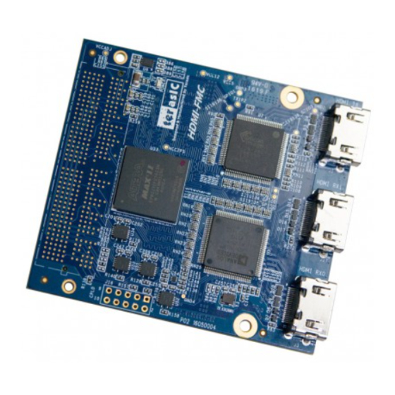
Chapter 2 Introduction of the HDMI-FMC Card This chapter describes the architecture and configuration of the HDMI-FMC Board including block diagram and components related. Figure 2-1 The HDMI-FMC Board PCB and Component Diagram of top side The Photographs of the HDMI-FMC are shown in Figure 2-1 Figure 2-2. -
Page 6: Features
⚫ FMC Connector (HPC) 2-1 Features The HDMI-FMC card has many features that allow users to implement a wide range of design circuits, from simple circuits to various multimedia projects. The following hardware is provided on the board: Package Interface:VITA 57.1 FMC, adjustable I/O-standard(1.5/1.8/2.5/3.0V). - Page 7 ⚫ HDMI 1.4a/1.3, HDCP 1.4 and DVI Compliant ⚫ Video formats:4:4:4 RGB, 4:4:4/4:2:2 YCbCr ⚫ Pixels resolution:4Kx2K@30Hz ⚫ Pixels clock:DDR/SDR up to 300MHz ⚫ 3D format support ⚫ High Bitrate Audio support - 6 - HDMI-FMC_User_Manual www.terasic.com August 6, 2019...
-
Page 8: Block Diagram Of The Hdmi-Fmc Board
Below Figure 2-3 shows the HDMI-FMC Block Diagram. Level shift module outputs audio and video image data from FMC connector, which can be converted to TMDS data by passing through the Sil9136-3 to the HDMI TX connector. Similarly, HDMI RX connector receives all mandatory 3D TV formats defined in the HDMI 1.4a specification through a dual input HDMI-capable, which can be... -
Page 9: Connectivity
2-3 Connectivity Terasic HDMI-FMC is able to connect on to any FPGA development kit equiped with FMC Figure 2-4, Figure 2-5 Figure 2-6 (High-Pin Count) connector. The Below pictures show the connections with three different Terasic FPGA Boards: Figure 2-4 Connect the HDMI-FMC to TR5 board’s FMCD port... - Page 10 Figure 2-5 Connect the HDMI-FMC to A10SoC board’s FMCA port Figure 2-6 Connect the HDMI-FMC to Terasic HAN Pilot Platform FMC port - 9 - HDMI-FMC_User_Manual www.terasic.com August 6, 2019...
-
Page 11: Chapter 3 Using The Hdmi-Fmc Board
Using the HDMI-FMC Board This chapter provides instructions on how to use Sil9136-3, ADV7619, Level shift and FMC connector on the HDMI-FMC board. 3-1 Sil9136-3 Sil9136-3 is a HDMI Deep Color transmitter and can deliver up to 16-bit Deep Color at 1080p/30Hz resolutions and 12-bit Deep Color at 1080p/60Hz resolutions. - Page 12 Therefore, a mechanism is provided for accessing single bytes. Where defined, Internal Registers are accessed as noted below. 1. Set Page 2. Select Indexed Offset within Page 3. Obtain Read/Write Register Access 0xBC 0xBD 0xBE - 11 - HDMI-FMC_User_Manual www.terasic.com August 6, 2019...
- Page 13 0x60[7] = 0 method host → TPI: Define parameters for embedded sync Configure Embedded 0x62–0x6D method Sync Extraction w/ 0x60[7] = 1 Note that the TPI 0x63 values must be rewritten after - 12 - HDMI-FMC_User_Manual www.terasic.com August 6, 2019...
- Page 14 Table 3-1 Register Group Summary Group Register What Firmware Does with these Register Name Function Addresses Registers Identification 0x1B–1D Identification Identifies the chip and version of TPI - 13 - HDMI-FMC_User_Manual www.terasic.com August 6, 2019...
- Page 15 The ID registers return the device ID and TPI revision ID. The ID registers are listed in Table 3-2. HDCP-capable and non HDCP-capable transmitters are distinguishable only by reading the HDCP revision register (TPI 0x30). Access. These registers are accessed as single bytes. - 14 - HDMI-FMC_User_Manual www.terasic.com August 6, 2019...
- Page 16 1 – full 1 – Falling 01 – x1 (default) 0011 – Pixels are sent four times each pixel wide edge 10 – x2 All others – Rsvd (default) 11 – x4 - 15 - HDMI-FMC_User_Manual www.terasic.com August 6, 2019...
- Page 17 Range Compression. Range compression is enabled when RGB input and YCbCr output conversion is selected. Range Expansion. Range expansion is enabled when YCbCr input and RGB output conversion is selected. - 16 - HDMI-FMC_User_Manual www.terasic.com August 6, 2019...
- Page 18 10 – YCbCr 4:2:2 Depth conversion 10 – 10-bit 0 – Disable 1 – BT.709 10 – On 11 – RGB (same as 11 – 12-bit 1 – Enable 11 – Rsvd conversion - 17 - HDMI-FMC_User_Manual www.terasic.com August 6, 2019...
- Page 19 ⚫ DE Generation (when explicit HSYNC and VSYNC signals are provided) ⚫ Sync Extraction (when incoming video uses the ITU 656 method for embedding sync - 18 - HDMI-FMC_User_Manual www.terasic.com August 6, 2019...
- Page 20 0x61 detected polarity detected polarity 0 – non 0 – active [00] RSVD RSVD RSVD RSVD RSVD detected 0 – active high interlaced high (leading 1 – interlaced edge rises) (leading edge - 19 - HDMI-FMC_User_Manual www.terasic.com August 6, 2019...
- Page 21 Note that Audio InfoFrame byte 1 must also have this same setting. 9. Again write register TPI 0x26 with I2S selected, this time with Mute disabled (bit [4] = 0). - 20 - HDMI-FMC_User_Manual www.terasic.com August 6, 2019...
- Page 22 0 – No swap 01 – FIFO#1 only) 1 – Enable 10 – SD2 0 – Disable 1 – Swap 10 – FIFO#2 11 – SD3 1 – Enable 11 – FIFO#3 - 21 - HDMI-FMC_User_Manual www.terasic.com August 6, 2019...
- Page 23 Original f , Channel Status bits 39:36 0101 – 22 bits [0B] Refer to IEC60958 specification 1101 – 21 bits 1010 – 20 bits 1000 – 19 bits 0100 – 18 bits - 22 - HDMI-FMC_User_Manual www.terasic.com August 6, 2019...
- Page 24 Security Audio RxSense Hot Plug pin Receiver Hot Plug / 0x3D Authentication Value Status Error current state current state Sense Event Connection [00] status change ready Change Event pending or Event pending - 23 - HDMI-FMC_User_Manual www.terasic.com August 6, 2019...
- Page 25 TPI Interrupt Status register in place of the Receiver Sense status bit. In this way, a single register read is adequate to check all interrupt sources at once. Setting TPI 0x3C[3] = 1 allows - 24 - HDMI-FMC_User_Manual www.terasic.com August 6, 2019...
- Page 26 0 = Disable 0 = Unstable 1 = Stable 1 = Enable 1 = Enable 1 = Stable Software Reset – Reset all sections, including the audio FIFO, except registers that are user configurable. - 25 - HDMI-FMC_User_Manual www.terasic.com August 6, 2019...
-
Page 27: Adv7619
Figure 3-2 noise in the audio output. shows the system block diagram of ADV7619. Figure 3-2 ADV7619 HDMI receiver - 26 - HDMI-FMC_User_Manual www.terasic.com August 6, 2019... -
Page 28: Level Shift
LSF0102 is a 2 channel bidirectional voltage level translator operational from 0.95 to 4.5 V on A port 1.8 to 5.5 V on B port. TXB0104 is a 4-bit bidirectional voltage level translator with auto direction - 27 - HDMI-FMC_User_Manual www.terasic.com August 6, 2019... - Page 29 I2C and audio data. Figure 3-3, Figure 3-4, Figure 3-5 gives an illustration of the level shift. Figure 3-3 Voltage translation of I2C for Receiver Figure 3-4 Voltage translation of audio data for receiver - 28 - HDMI-FMC_User_Manual www.terasic.com August 6, 2019...
-
Page 30: Fmc Connector
Figure 3-5 Level shift(EPM2210) 3-4 FMC Connector Table 3-13 shows the pin out and pin definitions of the FMC connector. Table 3-13 Pin Assignment of HDMI-FMC FMC interface Signal Name Pin Direction Description I/O Standard TX_PCLK Input Transmitter pixel data clock 1.5/1.8/2.5/3.0/3.3V... - Page 31 Transmitter video red data 10 1.5/1.8/2.5/3.0/3.3V TX_RD11 Input Transmitter video red data 11 1.5/1.8/2.5/3.0/3.3V Transmitter audio input master clock(I2S、 TX_MCLK Input 1.5/1.8/2.5/3.0/3.3V S/PDIF Mode) Transmitter I2S serial clock(I2S、S/PDIF TX_SCK Input 1.5/1.8/2.5/3.0/3.3V Mode)、DSD clock(DSD Mode) - 30 - HDMI-FMC_User_Manual www.terasic.com August 6, 2019...
- Page 32 RX_BD1 Output Receiver video blue data 1 1.5/1.8/2.5/3.0/3.3V RX_BD2 Output Receiver video blue data 2 1.5/1.8/2.5/3.0/3.3V RX_BD3 Output Receiver video blue data 3 1.5/1.8/2.5/3.0/3.3V RX_BD4 Output Receiver video blue data 4 1.5/1.8/2.5/3.0/3.3V - 31 - HDMI-FMC_User_Manual www.terasic.com August 6, 2019...
- Page 33 RX_RD3 Output Receiver video red data 3 1.5/1.8/2.5/3.0/3.3V RX_RD4 Output Receiver video red data 4 1.5/1.8/2.5/3.0/3.3V RX_RD5 Output Receiver video red data 5 1.5/1.8/2.5/3.0/3.3V RX_RD6 Output Receiver video red data 6 1.5/1.8/2.5/3.0/3.3V - 32 - HDMI-FMC_User_Manual www.terasic.com August 6, 2019...
- Page 34 Note : 1. For I/O standard, 3.0 V is applied to High-end FPGAs and 3.3 V is applied to Low Cost and Power FPGAs. 2. The RX pixel color-bit plane is adjustable accord to the video interface data format settings,including video format and data width. - 33 - HDMI-FMC_User_Manual www.terasic.com August 6, 2019...
-
Page 35: Chapter 4 Example Codes
Chapter 4 Example Codes This chapter provides NIOS based examples for users to get started using the HDMI-FMC board. 4-1 4K HDMI Loopback Demonstration The Loopback demonstration establishes connection between the HDMI Receiver input to the transmitter output of the HDMI daughter board. The Loopback (Internal bypass) generates the HDMI... - Page 36 Figure 4-1 System block diagram of the HDMI loopback demonstration ◼ HAN Loopback Demonstration Setup Figure 4-2 shows the hardware setup of loopback demonstration for Terasic HAN Pilot Platform. - 35 - HDMI-FMC_User_Manual www.terasic.com August 6, 2019...
- Page 37 Connect the FMC-HDMI daughter board to HAN board via FMC connector and make sure the screws on the HDMI-FMC card have been tightened firmly. Connect the 4K HDMI monitor and the HDMI TX port with a HDMI cable, power on the monitor and make sure the monitor is set to HDMI input mode.
- Page 38 Power on Han board. Execute the batch file test.bat under the folder “\HAN_HDMI_FMC\demo_batch”. Note:Do not attempt to connect/remove the HDMI-FMC daughter board to/from the main board when the power is on, or the hardware could be damaged. ◼ TR5 Loopback Demonstration Setup Figure 4-3 shows the hardware setup of loopback demonstration for Terasic TR5 FPGA Mainboard.
- Page 39 2. The TR5 FMC A connector I/O standard should be set to the same as HDMI-FMC card 2.5V I/O standard. Short Pin 7 & 8 of JP5 header on TR5 board to set the FMC A connector VCCIO Voltage to 2.5V (User can refer to section 2.2 of TR5 User Manual for detail).
- Page 40 (our FMC definition is based on standard), so there are some reserved resistors on the Intel A10SoC Production board design for users to switch the circuit. Users need to rework three groups of resistors to make the HDMI-FMC card working on the A10SoC Production board normally.
- Page 41 Figure 4-5 The resistors need to be reworked Figure 4-6 The resistors need to be reworked Figure 4-7 shows the resistors (that need to be reworked) positions on A10SoC Production board PCB. - 40 - HDMI-FMC_User_Manual www.terasic.com August 6, 2019...
- Page 42 Make sure Quartus 18.1 or later version has been installed on your PC. Program the max5.pof code into A10SoC I/O MAX V as the steps below: ⚫ Set the switches of the SW3 as shown in the Figure 4-8 first. - 41 - HDMI-FMC_User_Manual www.terasic.com August 6, 2019...
- Page 43 A10SoC board, open the Quartus Programmer tool, click Auto Detect, see Figure 4-9. Figure 4-9 Quartus Programmer windows ⚫ Select the max5.pof file (in the …\A10SoC_HDMI_FMC\demo_batch folder) into the MAX V device, see Figure 4-10. - 42 - HDMI-FMC_User_Manual www.terasic.com August 6, 2019...
- Page 44 ⚫ Click Start button to program as shown in Figure 4-11. Figure 4-11 Program the max5.pof ⚫ After programming successfully, power off the A10SoC board and set the switches of the SW3 as shown in Figure 4-12. - 43 - HDMI-FMC_User_Manual www.terasic.com August 6, 2019...
- Page 45 Connect the FMC-HDMI daughter board to A10SoC board via FMCA connector and make sure the screws on the HDMI-FMC card have been tightened firmly. Connect the 4K HDMI monitor and the HDMI TX port with a HDMI cable, power on the monitor and make sure the monitor is set to HDMI input mode.
-
Page 46: Appendix
2019/6/28 Modify section 4-1, add new operation step 2 for TR5 demo V1.6 2019/08/05 Add HAN+HDMI-FMC demo, change the A10SoC ES board to A10SoC Production board 5-2 Copyright Statement Copyright © 2017 Terasic Inc. All rights reserved. - 45 - HDMI-FMC_User_Manual www.terasic.com...
Need help?
Do you have a question about the HDMI-FMC and is the answer not in the manual?
Questions and answers