Table of Contents
Advertisement
®
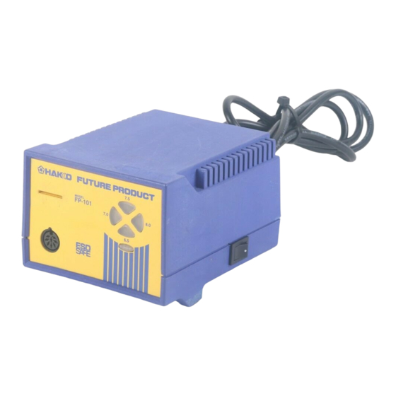
High-output, temperature controlled
Thank you for purchasing the FP-101 soldering station. This
high-output, temperature controlled soldering station uses a
composite tip, incorporating heater and sensor functions into
one element. Several process control features unique to the
FP-101 make it applicable to a broad range of soldering
applications.
Please read this manual before operating the FP-101. Keep
this manual readily accessible for reference.
1. PACKING LIST ............................................................... 1
2. SPECIFICATIONS .......................................................... 1
4. PART NAMES ................................................................. 3
5. INITIAL SETUP .............................................................. 3
6. OPERATION ................................................................... 5
7. PARAMETER SETTINGS ............................................... 6
8. MAINTENANCE ............................................................. 7
9. ERROR MESSAGES ...................................................... 9
10. TROUBLE SHOOTING GUIDE .................................... 10
11. PARTS LIST .................................................................. 11
12. TIP STYLES ................................................................. 13
13. WIRING DIAGRAM ....................................................... 15
soldering station
Instruction Manual
TABLE OF CONTENTS
Advertisement
Table of Contents

Related Manuals for Hakko Electronics FP-101


Summary of Contents for Hakko Electronics FP-101
-
Page 1: Table Of Contents
Several process control features unique to the FP-101 make it applicable to a broad range of soldering applications. Please read this manual before operating the FP-101. Keep this manual readily accessible for reference. -
Page 2: Packing List
Tip to ground resistance panel indicate the heat range selected Tip to ground potential < 2 mV for the FP-101 (6.5 = ~650°F. [343°C]; Length, less cord 188 mm (7.4 in.) with 2.4D tip 7.0 = ~700°F. [371°C]; 7.5 = ~750°F. -
Page 3: Warnings, Cautions, Notes And Examples
Do not remove or damage the bar code sticker. CAUTION To prevent accidents or damage to the FP-101, be sure to observe the following: Do not use the FP-101 for applications other than soldering. Do not allow the FP-101 to become wet, or use it with wet hands. -
Page 4: Part Names
7 .0 8 .0 green 6 .5 Card slot ® FP-101Soldering station MODEL FP-101 Control card The heat range selector button Auto power shutoff switch Receptacle (on the bottom front of the case) Card chain Tip cleaner Tip (not included) - Page 5 2. Plug the power cord into a grounded wall Push the connector in as far as socket. The FP-101 is protected against it will go. When the plug clicks, it is fully inserted. electrostatic discharge and must be grounded for full efficiency.
-
Page 6: Operation
Each FP-101 comes with a small card, which inserts into the Card slot on the front of the unit. This card is used when changing heat ranges. Any FP-101 card can be used with any FP-101 soldering station. Changing the heat range 1. -
Page 7: Parameter Settings
Using the iron holder Remove any excess solder from the tip by thrusting the tip into the cleaning wire. (Do not wipe the tip against the wire. This may cause molten solder to spatter.) When the wire become dirty or loaded with solder, turn the wire until a clean surface is presented. -
Page 8: Maintenance
High temperatures shorten tip life and may cause thermal shock to components. Always use the lowest possible temperature when soldering. The excellent thermal recovery characteristics of the FP-101 ensure effective soldering at low temperatures. 2. Cleaning Always clean the soldering tip before use to remove any residual solder or flux adhering to it. - Page 9 Checking Procedure WARNING: Unless otherwise directed, carry out these procedures with the power switch OFF and the power UNPLUGGED. Check for a broken heater or 1. Check for a broken heater or sensor sensor Measure the resistance across this position. T7-D24 1Y100CB3 Verify the electrical integrity of the heater and...
-
Page 10: Error Messages
Soldering iron error The yellow and red heat range indicator lamps will blink if the connector cord is not attached to the station OR the wrong soldering iron is connected. NOTE: Only the FM-2021 is compatible with the FP-101. -
Page 11: Trouble Shooting Guide
10. TROUBLE SHOOTING GUIDE WARNING: • Before opening the FP-101, or replacing parts, be sure to disconnect the power plug. Failure to do so may result in electric shock. The unit does not CHECK : Is the plug disconnected? ACTION : Connect it. -
Page 12: Parts List
External tooth lock washer nominal size 4 7 . 5 7 . 0 8 . 0 6 . 5 Tapping screw 3 × 12 (1) FP-101 Station Item Part No. Part Name Description B2839 Control card B2834 Front panel with LED lens and... - Page 13 Item No. Part No. Part Name Specifications FM2021-01 Conversion kit is yellow FM2021-02 Connector assembly B2770 Connector cover B2765B Sleeve assembly Yellow B2768B Sleeve assembly Orange B2769B Sleeve assembly Blue B2300 Heat resistant pad • Iron Holder Item No. Part No. Part Name Specifications 634-01...
-
Page 14: Tip Styles
12. TIP STYLES (4.53) (5.47) Unit: mm (in.) T7-D08 SHAPE-0.8D Chisel T7-D12 SHAPE-1.2D Chisel T7-D16 SHAPE-1.6D Chisel T7-D24 SHAPE-2.4D Chisel (0.17) (0.02) (0.14) (0.02) (0.02) (0.16) (0.02) (0.12) (0.39) (0.39) (0.39) (0.37) T7-D32 SHAPE-3.2D Chisel T7-D4 SHAPE-4D Chisel T7-D52 SHAPE-5.2D Chisel T7-B SHAPE-B Conical (0.16) (0.05) - Page 15 Unit: mm (in.) T7-KU SHAPE-KU Knife T7-R20 SHAPE-2.0R Slot T7-R23 SHAPE-2.3R Slot T7-KL SHAPE-KL Knife (0.05) (0.05) (0.06) (0.07) (0.06) (0.43) (0.06) (0.43) (0.2) (0.2) T7-R27 SHAPE-2.7R Slot T7-R48 SHAPE-4.8R Slot T7-R34 SHAPE-3.4R Slot T7-1001 SOP5.1 x 4.6 (0.08) (0.09) (0.07) (0.23) (0.09)
-
Page 16: Wiring Diagram
13. WIRING DIAGRAM P.W.B./switch Grounding plate Fuse Power switch LED4 Transformer LED3 LED5 LED2 P.W.B./temperature control P.W.B./connector HEAD OFFICE 4-5, SHIOKUSA 2-CHOME, NANIWA-KU, OSAKA, 556-0024 JAPAN TEL:+81-6-6561-3225 FAX:+81-6-6561-8466 http://www.hakko.com AMERICAN HAKKO PRODUCTS, INC. 28920 N. AVENUE WILLIAMS VALENCIA CA 91355, U.S.A. TEL: (661) 294-0090 FAX: (661) 294-0096 Toll Free (800)88-HAKKO www.hakkousa.com 4 2 5 5 6...
Need help?
Do you have a question about the FP-101 and is the answer not in the manual?
Questions and answers