Table of Contents
Advertisement
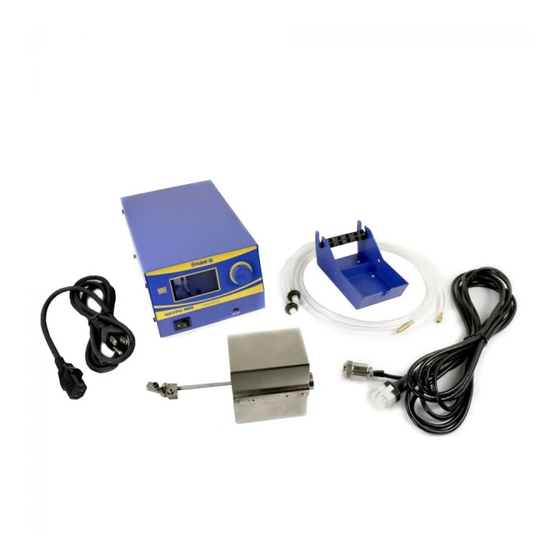
FU-500
Solder feed unit
Instruction Manual
Thank you for purchasing the HAKKO FU-500 solder feed unit.
Please read this manual before operating the HAKKO FU-500.
Keep this manual readily accessible for reference.
TABLE OF CONTENTS
●
●
......................................................... 1
................................................. 1
........................................................ 3
...................................................... 5
............................................................7
.....................................................18
...........................................19
................................21
................................................ 22
......................................................... 23
................. 2
Advertisement
Table of Contents

Related Manuals for Hakko Electronics FU-500


Summary of Contents for Hakko Electronics FU-500
-
Page 1: Table Of Contents
FU-500 Solder feed unit Instruction Manual ● Thank you for purchasing the HAKKO FU-500 solder feed unit. Please read this manual before operating the HAKKO FU-500. Keep this manual readily accessible for reference. ● TABLE OF CONTENTS 1. PACKING LIST ............ -
Page 2: Packing List
Please check the model number of your product before ordering corresponding parts according to the Part List on page 23. The solder diameter that can be used with the HAKKO FU-500 are shown in the table below. Before changing the solder diameter, see "● How to change the solder diameter" on page 17. -
Page 3: Warnings, Cautions And Notes
●Children should be supervised to ensure that they do not play with the appliance. ●To prevent accidents or damage to the HAKKO FU-500, be sure to observe the following. CAUTION ●The cutting blade is sharp. Be careful not to cut your fingers. -
Page 4: Part Names
4. PART NAMES ●HAKKO FU-500 Setting display LCD Control knob Power switch PC interface Feeder unit connector Slide unit connector Robot connector Fuse Connecting cable connector... - Page 5 ●Feeder Unit Feeder unit cover screw Solder feed guide set (option) To solder reel stand ※ Feeder unit cover Feed position adjuster CAUTION Teflon tube (option) ※Make sure to attach this cover to prevent a flux from entering into the feeder unit. CAUTION The solder feed pulley unit with the cutting blade is dangerous.
-
Page 6: Initial Setup
Ensure that solder is reeled out of With this condition, start the HAKKO FU-500 to feed solder the top of the bobbin. until solder comes out of the end of the teflon tube. - Page 7 ●Adjusting the solder feed position 1. Loosening the adjustment screw ① will allow you to move the entire solder feed guide set as shown in the figure below. Move the solder feed guide set to the tip. Adjustment screw ① 2.
-
Page 8: Operation
6. OPERATION Auto mode In auto mode, the unit operates according to commands from the robot. There are two types of auto mode: PS and DS. For more information, see the timing chart below: ・PS (Point soldering) mode Point soldering process Program No. - Page 9 ・DS (Drag Soldering) Mode Drag soldering process Program No. (In) Start solder feed (In) Controller ready (Out) Primary feed (Internal) Primary back feed (Internal) Unit down command (Out) Upper limit detection (In) Lower limit detection (In) Primary heating (Internal) Start continuous feed (Out) End continuous feed (In) Secondary feed (Internal) Secondary back feed (Internal)
- Page 10 Robot I/F pin assignment 2.54 mm pitch 26-pin ribbon cable connector No. 25 No. 26 HAKKO FU-500 back No. 25 No. 1 No. 26 No. 2 No. 1 No. 2 Pin No. Signal name Function Program No. LSB Program No.
- Page 11 Robot I/F input and output circuits Input circuit Output circuit 5.6K IO_Vsup 2∼10mA DCV48 or less, 50 mA or less (24V recommended) IO_GND DC24V OUT 500mA Max HAKKO FU-601 I/F Connecting cable (6-pole 6-core modular cable) Pin No. Signal name Function Incoming data Outgoing data...
- Page 12 Turn on the power switch of HAKKO FU-500. The start-up screen will be displayed, and then move to Auto Mode Standby screen. If the HAKKO FU-500 receives a Start signal when this screen is displayed, it will start to operate for Auto Mode.
- Page 13 ●Selecting Test Operation Mode When you select Test Operation Mode, you will enter Test Operation Mode. In this mode, the HAKKO FU-500 will start to operate in PS (point soldering) mode for operation check or adjustment after selecting a program number.
- Page 14 ●Selecting Solder Feed When you select Solder Feed, you will enter Solder Feed Mode. In this mode, you will specify the solder feed speed for continuous feed of solder. No signal will be output to the robot. All input signals from the robot will be ignored and no solder feed error will be detected.
- Page 15 In Program Setting Mode, the following settings can be made: Feed 1 : Primary Feed Length 0.1 - 99.9mm Feed Speed 1 : Primary Feed Speed 0.1 - 99.9mm/sec Back Feed 1 : Primary Back Feed Length 0 - 20.0mm Back Speed 1 : Primary Back Speed 0 - 99.9mm/sec...
- Page 16 ●Selecting Parameter Set When you select Parameter Set, you will enter Parameter Setting mode. In this mode, you can specify the operation of the entire system. Parameter Set Feed Speed 10.0 S-U Mode S-U Timeout Iron Connect Iron Status Exit 1.
- Page 17 4. Iron Connect (Connection status to the HAKKO FU-601) Iron Control Connection or Disconnection Connect When Not Connect is selected, preset settings can only Connection be made in the HAKKO FU-601 and no iron controller Disconnection error is detected. 5. Iron Status (Selecting the HAKKO FU-601 Ready or Error signal) Iron Control Status You can select which signal HAKKO FU-601 will output...
- Page 18 You can change the solder diameter by replacing the teflon tube, the solder feed guide set or the solder feed pulley unit. The compatible solder diameters varies by model number of the HAKKO FU-500. Please check your model number and then see the part list on the back cover of this manual when you need some part replacement.
-
Page 19: Maintenance
7. MAINTENANCE ■As a guide, perform maintenance/cleaning when replacing the solder. Remove any solder or flux adhered on the solder feed pulley unit using a brush or other appropriate tool. If an insufficient cutting depth or splashing of solder balls are found in spite of the proper maintenance, the cutting blade may have reached its end of life. -
Page 20: Error Messages
8. ERROR MESSAGES ●Solder feed trouble error When the solder feed sensor detects "no solder" or "clogging", the HAKKO FU-500 will immediately stop the feed and show Solder Feed this error message on the LCD along with buzzer sound. Trouble Push Knob ●Illegal input error... - Page 21 LCD along with buzzer sound. ●Emergency Stop Emergency Stop ! Upon receiving an emergency stop command from the robot, the HAKKO FU-500 will immediately stop the feed and show this error Push Knob message on the LCD along with buzzer sound.
-
Page 22: Trouble Shooting Guide
(See 11. PARTS LIST in page 23.) ●Illegal Input error is displayed. CHECK : Is the HAKKO FU-500 received any overlapped or illegal signal from the robot? ACTION : Check the robot program. ●Iron Controller Error is displayed. CHECK :... -
Page 23: Exploded View
10. EXPLODED VIEW ●HAKKO FU-500 ●Feeder unit... -
Page 24: Parts List
11. PARTS LIST For more information about replacement parts or latest information , please visit our website (http://www.hakko.com) or HAKKO Document Portal. (see below) Part No. Part Name Specifications Solder feed pulley unit BX1000 Solder feed pulley unit / 0.3 mm BX1001 Solder feed pulley unit / 0.5 mm...
Need help?
Do you have a question about the FU-500 and is the answer not in the manual?
Questions and answers