Table of Contents
Advertisement
Available languages
Available languages
Helios Ventilatoren
MONTAGE- UND BETRIEBSVORSCHRIFT
INSTALLATION AND OPERATING INSTRUCTIONS
NOTICE DE MONTAGE ET D'UTILISATION
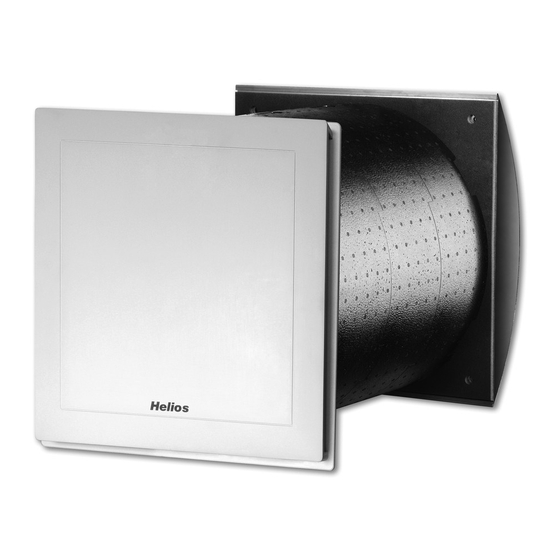
Wand-Einbaugerät
Wall installed unit
Groupe double-flux mural
KWL EC 60 Pro
KWL EC 60 Pro FF
- Wärmerückgewinnung und EC-Technik
für Einzelräume.
- Heat recovery and EC-motor technology
for single rooms
- Ventilation décentralisée avec récupération
de chaleur et moteurs EC.
D
NR. 86666
UK
NO. 86666
N° 86666
F
Advertisement
Chapters
Table of Contents

Related Manuals for Helios KWL EC 60 Pro


Summary of Contents for Helios KWL EC 60 Pro
- Page 1 NOTICE DE MONTAGE ET D’UTILISATION N° 86666 Wand-Einbaugerät Wall installed unit Groupe double-flux mural KWL EC 60 Pro KWL EC 60 Pro FF - Wärmerückgewinnung und EC-Technik für Einzelräume. - Heat recovery and EC-motor technology for single rooms - Ventilation décentralisée avec récupération...
-
Page 2: Table Of Contents
Montage KWL EC 60 Pro... Lüftungseinsatz ........ -
Page 3: Wichtige Informationen
Gewährleistung. Einsatzbereich – Anwendung Die Wärmerückgewinnungsgeräte KWL EC 60 Pro /... Pro FF sind für den Einbau in Außenwände zur Be- und Entlüf- tung von kleinen und großen Einzelräumen vorgesehen. Für eine mittelgroße Wohneinheit wird die Installation von zwei Geräten empfohlen. -
Page 4: 1.10 Elektrischer Anschluss
Montage- und Betriebsvorschrift Wand-Einbaugerät KWL EC 60 Pro / ... Pro FF 1.10 Elektrischer Anschluss WARNUNG Vor allen Wartungs- und Installationsarbeiten oder vor Öffnen des Schaltraumes ist das Gerät allpolig vom Netz zu trennen! Der elektrische Anschluss darf nur von einer autorisierten Elektrofachkraft entsprechend den nachstehenden Anschlussplänen ausgeführt werden. -
Page 5: Wandmontage Kwl 60 Rs Rohbauset
Montage- und Betriebsvorschrift Wand-Einbaugerät KWL EC 60 Pro / ... Pro FF Wandmontage KWL 60 RS Rohbauset KAPITEL 3 Kernbohrung in der Wand vornehmen (siehe Abb. 5). Anschl. Wandhülse in die Wand einschieben und einputzen. Um beim Einputzen eine Verformung der Wandhülse zu vermeiden, muss das Versteifungskreuz aus Styro- MONTAGE/AUFSTELLUNG por (siehe Abb. -
Page 6: Montage Kwl 60 Dr Distanzrahmen
Montage- und Betriebsvorschrift Wand-Einbaugerät KWL EC 60 Pro / ... Pro FF Montage KWL 60 DR Distanzrahmen Abb.10 SS-932 Funktionsbeschreibung zum Menübaum des Bedienelementes KWL-BC.. KAPITEL 4 A1 = Erstinbetriebnahme: Steigt die CO -Konzentration über Beginn des Urlaubs automatisch und... - Page 7 Montage- und Betriebsvorschrift Wand-Einbaugerät KWL EC 60 Pro / ... Pro FF D7 = Filterwechsel: E9 = Adresse Bedienelement: Das Filterwechselintervall kann zwi- Die Adresse des Bedienelements schen 2 bis 9 Monaten eingestellt kann nachträglich geändert werden. werden. Über eine Abfrage, kann die Dabei ist zu beachten, dass die Restlaufzeit für den Filterwechsel an-...
-
Page 8: Bedienmenü
Montage- und Betriebsvorschrift Wand-Einbaugerät KWL EC 60 Pro / ... Pro FF Bedienelement KWL-BC.. Das KWL-Wand-Einbaugerät wird mit einem Bedienelement KWL-BCU/BCA (für Unterputz oder Aufputzmontage) angesteuert. Es ermöglicht einen manuellen/automatischen 4-stufigen Betrieb. Dem Bedienelement liegt eine Steuer- leitung (3 m) mit beidseitigem RJ 12 Stecker zur einfachen Montage bei. Ein Anschluss von bis zu 4 Bedienelementen ist möglich. - Page 9 Montage- und Betriebsvorschrift Wand-Einbaugerät KWL EC 60 Pro / ... Pro FF C4.1.3 Montag (C4.1.3) C4.1.4 Montag (C4.1.4) C4.1.5 Montag (C4.1.5) C4.1.6 Montag (C4.1.6) C4.1.7 Montag kopieren (C4.1.7) C4.1.8 Montag kopieren (C4.1.8) C5.1 Urlaubsprogramm (C5) Urlaubsprogramm (C5.1) EIN/AUS Werkseinstellung AUS NOTIZEN: .
- Page 10 Montage- und Betriebsvorschrift Wand-Einbaugerät KWL EC 60 Pro / ... Pro FF C5.5.2 C5.5.1 Intervallzeit (C5.5.2) 1-24 h Werkseinstellung 1h Lüftungsstufe (C5.5.1) Stufe 1 - AB ............. . .
- Page 11 Montage- und Betriebsvorschrift Wand-Einbaugerät KWL EC 60 Pro / ... Pro FF Schaltstufen (D1.3) D1.3 00 % r.F Werkseinstellung 10 D1.4 Nachlaufzeit (D1.4) 1-4 Stunden Werkseinstellung 2 -Sollwerte (D2) D2.1 Status CO -Steuerung (D2.1) EIN/AUS Werkseinstellung EIN NOTIZEN: ............. . .
- Page 12 Montage- und Betriebsvorschrift Wand-Einbaugerät KWL EC 60 Pro / ... Pro FF D6.1 Zu- Abluftstufe (D6) Lüfterstufe Zuluft (D6.1) Stufe 1-4 Werkseinstellung 2 NOTIZEN: ............. . .
- Page 13 Montage- und Betriebsvorschrift Wand-Einbaugerät KWL EC 60 Pro / ... Pro FF D11.1 Wellenbeleuchtung (D11) Einstellung Findelicht (D11.1) 0-100 % Werkseinstellung 50 NOTIZEN: ............. . .
-
Page 14: Fehlermenü/Fehleranzeige Im Display
Montage- und Betriebsvorschrift Wand-Einbaugerät KWL EC 60 Pro / ... Pro FF Fehlermenü/Fehleranzeige im Display Bei einem Fehler wird die Fehlermeldung angezeigt, Leuchtdauer siehe Displaybeleuchtung. Ist das Display aus, blinkt der Drehencoder rot! E15.1 Luftfilter wechseln (B15) Luftfilter gewechselt (B15.1) JA/NEIN . -
Page 15: Elektrischer Anschluss
Montage- und Betriebsvorschrift Wand-Einbaugerät KWL EC 60 Pro / ... Pro FF Elektrischer Anschluss KAPITEL 5 Vor allen Wartungs- und Installationsarbeiten oder vor Öffnen des Schaltraumes ist das Gerät allpolig vom ELEKTROANSCHLUSS Netz zu trennen! Der elektrische Anschluss darf nur von einer autorisierten Elektrofachkraft entsprechend dem nachstehenden Anschlussplan ausgeführt werden. -
Page 16: Schaltplan Ss-958
Montage- und Betriebsvorschrift Wand-Einbaugerät KWL EC 60 Pro / ... Pro FF Schaltplan SS-958 für KWL EC 60 Pro / FF Abb.13... -
Page 17: Kondensatableitung
Vor allen Reinigungs- und Wartungsarbeiten ist das Gerät allpolig vom Netz zu trennen! ACHTUNG Gefährdung durch elektrischen Schlag, bewegliche Teile (Gebläse) und heiße Oberflächen. – Filter Das KWL EC 60 Pro... ist zu- und abluftseitig mit Klasse G4 Filter ausgestattet (nach DIN EN 1946, T.2): • Außenluft/Abluft: Ersatzluftfilter Grobfilter G4 ELF-KWL 60/4/4 Best.-Nr. - Page 18 ENGLISH Helios Ventilatoren INSTALLATION AND OPERATING INSTRUCTIONS NO. 86 666 Contents CHAPTER 1. GENERAL INFORMATION ............page 1 Important information .
-
Page 19: Important Information
Application - Operation The units with heat recovery KWL EC 60 Pro / ... Pro FF are designed for the installation in external walls to ventilate small and large single rooms. For a medium-sized flat the installation of two units is recommended The standard equipment permits the installation and the application in frost-free rooms>... -
Page 20: Electrical Connection
Installation and Operating Instructions Wall installed unit KWL EC 60 Pro / ... Pro FF 1.10 Electrical connection WARNING All work must be carried out with the equipment fully isolated from the power supply. The electrical connection are to be carried out in accordance with the relevant wiring diagram and are only to be done by a certified elec- trician. -
Page 21: Chapter 3. Installation
Installation and Operating Instructions Wall installed unit KWL EC 60 Pro / ... Pro FF Wall installation of KWL 60 RS first fix set CHAPTER 3 Drill a core hole in the external wall (see fig. 3). Then insert wall sleeve into the wall and plaster it in. -
Page 22: Installation Of Kwl 60 Dr Compensation Ring
Installation and Operating Instructions Wall installed unit KWL EC 60 Pro / ... Pro FF Installation of KWL 60 DR compensation ring fig.10 cut extension sleeve and attach extension partition element flush sleeve to wall sleeve with compensation ring Attach extension of... - Page 23 Installation and Operating Instructions Wall installed unit KWL EC 60 Pro / ... Pro FF D8 = Language: E11 = Software version: Language selection between Ger- Query to the current state of the soft- man, English, French or Italian. ware version of the main board and...
-
Page 24: Comfort Controller Kwl 60 Bc
Installation and Operating Instructions Wall installed unit KWL EC 60 Pro / ... Pro FF Comfort controller KWL-BC.. The KWL-wall installed unit is controlled by a comfort controller KWL-BCU/BCA (for flush or surface mounted installati It allows a manual or automatic 4-speed operation. A control line (3 m) with RJ 12 plugs on both sides is enclosed along with the comfort controller for easy assembly. - Page 25 Installation and Operating Instructions Wall installed unit KWL EC 60 Pro / ... Pro FF C4.1.3 Monday (C4.1.3) Monday Level Time Level Clock Exit C4.1.4 Monday (C4.1.4) Monday Level Time Level Level <Clock> C4.1.5 Monday (C4.1.5) Monday Level Time Level <Level>...
- Page 26 Installation and Operating Instructions Wall installed unit KWL EC 60 Pro / ... Pro FF C5.5.2 C5.5.1 Interval time (C5.5.2) Interval time Speed step 1-24 h factory setting 1h Speed step (C5.5.1) Level 1 – AB Level 1 - AB...
- Page 27 Installation and Operating Instructions Wall installed unit KWL EC 60 Pro / ... Pro FF Switching steps (D1.3) D1.3 Switching steps 00 % r.F Factory setting 10 Change Next D1.4 Run on time (D1.4) Run on time 1-4 hours Facrory setting 2...
- Page 28 Installation and Operating Instructions Wall installed unit KWL EC 60 Pro / ... Pro FF D6.1 Intake/Extract air level (D6) Speed step Speed step intake (D6.1) intake air Level 1-4 Factory setting 2 Level 1-4 Intake/Extract air level Change Next NOTES: .
- Page 29 Installation and Operating Instructions Wall installed unit KWL EC 60 Pro / ... Pro FF D11.1 Knob light (D11) Setting location light (D11.1) Setting location light 0-100 % Factory setting 50 Knob light NOTES: ..............
-
Page 30: Error Menu/Error Message In The Display
Installation and Operating Instructions Wall installed unit KWL EC 60 Pro / ... Pro FF Error menu / Error message in display In case of an error the error message is indicated. Burn time see display lighting. If the display is off, the rotory encoder flashes red! E15.1... -
Page 31: Chapter 5. Electrical Connection
Installation and Operating Instructions Wall installed unit KWL EC 60 Pro / ... Pro FF Electrical connection CHAPTER 5 All work must be carried out with the equipment fully isolated from the power supply. The electrical connection ELECTRICAL are to be carried out in accordance with the relevant wiring diagram and are only to be done by a certified elec- CONNECTION trician. -
Page 32: Wiring Diagram Ss-958
Installation and Operating Instructions Wall installed unit KWL EC 60 Pro / ... Pro FF Wiring diagram SS-958 for KWL EC 60 Pro / FF fig.13... -
Page 33: Chapter 6. Cleaning And Maintenance
Danger by electrical impact, mobile parts (fan) and hot surfaces. – Filter The KWL EC 60 Pro.. is supplied with filters of class G4 in the supply and extract air stream (according to DIN EN 1946, T.2) • Supply air / Extract air ELF-KWL 60/4/4 Ref.No. - Page 34 Montage de l’unité de ventilation KWL EC 60 Pro /...Pro FF ......
-
Page 35: Informations Importantes
Domaine d’utilisation Le groupe double flux mural à récupération de chaleur KWL EC 60 Pro /... Pro FF est conçu pour l’insufflation et l’ex- traction d’air dans les petits et grands locaux individuels. Pour les locaux nécessitant des débits d’air plus importants, nous conseillons l’utilisation de deux appareils. -
Page 36: 1.10 Raccordement Électrique
Notice de montage et d’utilisation Groupe double flux mural KWL EC 60 Pro / ... Pro FF 1.10 Raccordement électrique ATTENTION Mettre impérativement l’appareil hors tension avant tous travaux d’entretien ou à l’ouverture du boîtier de commande ! Le branchement électrique doit être réalisé, conformément aux schémas de raccordement ci- dessous, uniquement par un électricien qualifié. -
Page 37: Montage Mural Du Kit Gros Oeuvre Kwl 60 Rs
Notice de montage et d’utilisation Groupe double flux mural KWL EC 60 Pro / ... Pro FF Montage mural du kit gros oeuvre KWL 60 RS CHAPITRE 3 Effectuer un carottage dans le mur (voir fig. 5). Insérer ensuite le manchon dans le trou puis sceller. Introduire le raidisseur en polystyrène (voir fig. -
Page 38: Descriptif Des Différentes Fonctions
Notice de montage et d’utilisation Groupe double flux mural KWL EC 60 Pro / ... Pro FF Montage entretoise pour murs < 350 mm KWL 60 DR Fig.10 Emboîter la virole sur le manchon mural Couper le manchon mural et son renfort au ras de l’entretoise... - Page 39 Notice de montage et d’utilisation Groupe double flux mural KWL EC 60 Pro / ... Pro FF D7= Changement des filtres : E11= Version logiciel : L’intervalle de remplacement des Indique la version du programme de filtres est paramétrable de 2 à 9 mois.
-
Page 40: Arborescence Du Menu
Notice de montage et d’utilisation Groupe double flux mural KWL EC 60 Pro / ... Pro FF Commande à distance KWL-BC.. Le groupe double KWL flux mural est piloté par une commande à distance KWL-BCU (pour montage encastré / KWL-BCA (pour montage apparent) permettant un fonctionnement à 4 étages en mode manuel ou automatique. - Page 41 Notice de montage et d’utilisation Groupe double flux mural KWL EC 60 Pro / ... Pro FF C4.1.3 Lundi (C4.1.3) Lundi Vit. Heure Vit. Heure Sortie C4.1.4 Lundi (C4.1.4) Lundi Vit. Heure Vit. Vitesse <Heure> C4.1.5 Lundi (C4.1.5) Lundi Vit.
- Page 42 Notice de montage et d’utilisation Groupe double flux mural KWL EC 60 Pro / ... Pro FF C5.5.2 C5.5.1 Intervalle temps(C5.5.2) Intervalle temps Vitesse 1-24 h Réglage usine 1 h Vitesse ventilation (C5.5.1) 1 - 24 h Vitesse 1 - REP...
- Page 43 Notice de montage et d’utilisation Groupe double flux mural KWL EC 60 Pro / ... Pro FF Etages commutation (D1.3) D1.3 00 % HR Etages commutation Réglage usine : 10 Modifier Suivant D1.4 Post-ventilation (D1.4) 1-4 heures Post-ventilation Réglage usine : 2...
- Page 44 Notice de montage et d’utilisation Groupe double flux mural KWL EC 60 Pro / ... Pro FF C5.5.2 C5.5.1 Intervalle temps(C5.5.2) Intervalle temps Vitesse 1-24 h Réglage usine 1 h Vitesse ventilation (C5.5.1) 1 - 24 h Vitesse 1 - REP...
- Page 45 Notice de montage et d’utilisation Groupe double flux mural KWL EC 60 Pro / ... Pro FF Etages commutation (D1.3) D1.3 00 % HR Etages commutation Réglage usine : 50 Modifier Suivant D1.4 Post-ventilation (D1.4) 1-4 heures Post-ventilation Réglage usine : 0...
-
Page 46: Liste Des Messages D'erreur
Notice de montage et d’utilisation Groupe double flux mural KWL EC 60 Pro / ... Pro FF Liste des messages d’erreur Si un dysfonctionnement survient, un message d’erreur s’affiche. Pour le réglage du témoin défaut voir paragraphe Eclaira- ge écran. Si l’écran de la commande est éteint, la molette clignote en rouge. -
Page 47: Raccordement Électrique
Notice de montage et d’utilisation Groupe double flux mural KWL EC 60 Pro / ... Pro FF Raccordement électrique CHAPITRE 5 Mettre impérativement l’appareil hors tension avant tous travaux d’entretien ou à l’ouverture du boîtier de commande! Le branchement électrique doit être réalisé, conformément aux schémas de raccordement ci-des- RACCORDEMENT sous, uniquement par un électricien qualifié. -
Page 48: Schéma De Branchement Ss-958
Notice de montage et d’utilisation Groupe double flux mural KWL EC 60 Pro / ... Pro FF Schéma de branchement SS-958 pour KWL EC 60 Pro / ... Pro FF Fig.13... -
Page 49: Evacuation Des Condensats
éviter tout risque lié au choc électrique, aux pièces tournantes et aux surfaces chaudes. – Filtres Le groupe double-flux KWL EC 60 Pro / ... Pro FF est équipé de deux filtres à air classe G4, placé sur l’air rejeté et l’air soufflé (selon la norme DIN EN 1946, T.2): •... - Page 50 HELIOS Ventilatoren GmbH + Co KG · Lupfenstraße 8 · 78056 VS-Schwenningen HELIOS Ventilateurs · Le Carré des Aviateurs · 157 avenue Charles Floquet · 93155 Le Blanc Mesnil Cedex CH HELIOS Ventilatoren AG · Steinackerstraße 36 · 8902 Urdorf GB HELIOS Ventilation Systems Ltd.
Need help?
Do you have a question about the KWL EC 60 Pro and is the answer not in the manual?
Questions and answers