Sign In
Upload
Manuals
Brands
Gotting Manuals
Antenna
HG 98860ZA
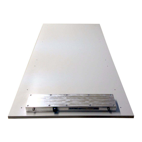
User Manuals: Gotting HG 98860ZA Identification Antenna
Manuals and User Guides for Gotting HG 98860ZA Identification Antenna. We have
1
Gotting HG 98860ZA Identification Antenna manual available for free PDF download: Technical Description
Gotting HG 98860ZA Technical Description (59 pages)
2-dim. Positioning and Identification Antenna Outdoor
Brand:
Gotting
| Category:
Antenna
| Size: 1 MB
Table of Contents
Table of Contents
2
1 Introduction
5
Figure 1 Examples of Automated Vehicles Using Transponder Systems
5
Figure 2 System Components (Optional Extras in Brackets)
6
Function
6
System Components
6
Application Example
7
Definitions
7
Figure 3 Track Guiding a Vehicle with One Antenna
7
Figure 4 Polarity of the Deviation
7
2 Installation
8
Transponder HG 70653ZA
8
Antenna HG 98860ZA
8
Figure 5 Antenna Dimensions
8
Figure 6 Application of the Washers While Mounting the Antenna
8
3 Installation / Commissioning
10
Figure 7 Diagram: Commissioning Protocol / Insignificant Interference Level; Shown Is the Sum Voltage over the Travelled Distance
11
Figure 8 Diagram: Commissioning Protocol / Undisturbed Transponder Decoding
11
Figure 9 Diagram: Commissioning Protocol / High Interference Level; Shown Is the Sum Voltage over the Traveled Distance
12
Figure 10 Diagram: Commissioning Protocol / Jammed Decoding (Function Still Ensured)
13
Figure 11 Diagram: Commissioning Protocol / False POSI Pulse Generated through Noise and Threshold Set too Low
13
4 Components and Operation
15
Components in the Ground
15
Transponders
15
Transmitter-Receiver Antenna HG 98860ZA
15
Figure 12 Photo Transmitter-Receiver Antenna HG 98860ZA
15
Figure 13 Drawing Antenna HG 98860ZA (with Casing Dimensions)
16
Connection
17
Figure 14 16-Pin Antenna Connection Socket
17
Table 1 Allocation of the 16 Pin Antenna Connection Socket
17
Turn-On Characteristics
17
Figure 15 Formula: Minimum Update Rate
18
Interfaces
18
List of the System Data Which Can be Output
18
Serial (RS 422)
18
Table 2 Data Words in a Telegram with 21 Byte Length
19
Table 3 Possible System Status Messages
20
List of Commands
22
Table 4 List of the System Commands
22
CAN Bus
25
CAN Bus Infrastructure
25
CAN Message Object 1 (Transmission Object)
25
Description of the CAN Protocol
25
Figure 16 CAN Bus Infrastructure (Example)
25
System Monitor
25
Table 5 Structure of the CAN Message Object 1
25
CAN Message Object 2 (Transmission Object)
26
CAN Message Object 3 (Transmission Object)
26
Table 6 Structure of the CAN Message Object 2
26
Table 7 Structure of the CAN Message Object 3
26
Analysis Interface
27
CAN Message Object 4 (Reception Object)
27
Positioning Pulse
27
Table 8 Structure of the CAN Message Object 4
27
Table 9 Coding of Commands
27
Connection Cable HG 09240DB
28
Software Download
28
Table 10 Connection Cable Pin Allocation
28
5 Software
30
Terminal Program
30
Parameter Settings
30
Table 11 Terminal Settings for the Monitor Program
30
System Monitor
31
How to Start the Monitor Program
31
How to Work with the Monitor Program
32
Figure 17 Main Menu of the Monitor Program
33
Main Menu
33
Table 12 Description of System Variables (Monitor Program)
33
Figure 18 Menu: (S)Erial Output
35
S)Erial Output
35
Figure 19 Menu: „(D)Isplay Telegram Content
36
Figure 20 Menu: (T)Ime & Code
37
T)Ime & Code
37
F)Requency & Antenna Tuning
38
Figure 21 Menu: (F)Requency & Antenna Tuning
38
Figure 22 Formula: Calculation of the Receiver Frequency
38
C(A)N-Parameters
39
Figure 23 Menu: C(A)N-Parameters
39
Cs(V)
40
Display (X)Histogram
41
Figure 24 Menu: Display (X)Histogram
41
Display (Y)Histogram / (+)
42
Figure 25 Menu: Display (Y)Histogram
42
Import (1) / Export (2) User Parameter
43
L)Oad Values to Eeprom
43
P(R)Int Parameters
43
U)Pdate Firmware
43
Software Update (Antenna Software)
44
Installation of the ST10-Flasher Program for Software Update
44
Software Update
44
Figure 26 Update Program: Operating Elements
45
Figure 27 Update Program: Programming Procedure
45
6 Maintenance
46
7 Trouble Shooting
47
Table 13 Trouble Shooting
47
8 Technical Data
48
Transmitter-Receiver Antenna
48
Table 14 Technical Data Antenna HG 98860ZA
48
Connection Cable
49
Table 15 Technical Data Connection Cable HG 09240DB
49
9 Appendix
50
Procedure 3964R
50
Data Direction Antenna -> SPS
50
Figure 28 Diagram Procedure 3964R; Antenna -> SPS
50
Data Direction SPS -> Antenna
51
B Procedure „Transparent
51
Data Direction Antenna -> SPS
51
Figure 29 Diagram Procedure 3964R; SPS -> Antenna
51
C Influence of a Metal Plate on the Antenna
52
D Influence of a Metal Frame on the Antenna
52
Table 16 Influence of Metal on the Antenna
52
Table 17 Influence of Metal on the Antenna
52
E Influence of Reinforcement Steel Mesh below the Transponder
53
Figure 30 Test Setup with Transponder and Reinforcement Mat
53
Table 18 Influence of Reinforcement Steel Mesh on the Transponder
53
F Accuracy of the Deviation Calculation
54
Figure 31 Typical Accuracy of They-Deviation
54
Figure 32 Typical Accuracy of the X-Deviation
54
List of Figures
55
11 List of Tables
56
12 Index
57
13 Handbook Conventions
58
14 Copyright and Terms of Liability
59
Copyright
59
Exclusion of Liability
59
Advertisement
Advertisement
Related Products
Gotting HG 98780-A
Gotting HG G-98780-A
Gotting HG G-98760-C Series
Gotting HG G-19334-A
Gotting HG G-19334
Gotting HG G-98830
Gotting HG G-71915
Gotting HG G-98870
Gotting HG G-98870 YA
Gotting HG G-98835
Gotting Categories
Antenna
GPS
Accessories
Marine Radio
Controller
More Gotting Manuals
Login
Sign In
OR
Sign in with Facebook
Sign in with Google
Upload manual
Upload from disk
Upload from URL