
Related Manuals for Queclink GV57MG


Summary of Contents for Queclink GV57MG
- Page 1 GV57MG User Manual GV57MG User Manual EGPRS/LTE Cat-M1/LTE Cat-NB2/GNSS Tracker TRACGV57MGUM001 Version: 2.01 TRACGV57MGUM001 - 0 -...
- Page 2 Document Control ID TRACGV57MGUM001 General Notes Queclink offers this information as a service to its customers, to support application and engineering efforts that use the products designed by Queclink. The information provided is based upon requirements specifically provided to Queclink by the customers.
-
Page 3: Table Of Contents
GV57MG User Manual Contents Contents............................2 Table Index ............................3 Figure Index ............................ 4 0. Revision History ......................... 5 1. Introduction ..........................6 1.1 Reference ..........................6 1.2 Terms and Abbreviations ..................... 6 2. Product Overview ........................7 2.1 Check Parts List ........................7 2.2 Parts List .......................... - Page 4 GV57MG User Manual Table Index TABLE 1: GV57MG PROTOCOL REFERENCE ................6 TABLE 2: TERMS AND ABBREVIATIONS ..................6 TABLE 3: GV57MG PARTS LIST ....................... 8 TABLE 4: DESCRIPTION OF 5-PIN CONNECTIONS ..............8 TABLE 5: ELECTRICAL CHARACTERISTICS OF IGNITION DETECTION ......12 TABLE 6: ELECTRICAL CHARACTERISTICS OF DIGITAL INPUT...........
- Page 5 FIGURE 5. TYPICAL DIGITAL INPUT CONNECTION..............13 FIGURE 6. INTERNAL DRIVER CIRCUIT FOR DIGITAL OUTPUT .......... 14 FIGURE 7. TYPICAL CONNECTION WITH A RELAY ..............14 FIGURE 8. GV57MG LEDS ON THE CASE ................... 15 FIGURE 9. MOTION SENSOR DIRECTION ................... 16 TRACGV57MGUM001...
-
Page 6: Revision History
GV57MG User Manual 0. Revision History Version Date Author Description of Change 1.00 2020-12-14 Oliver Ding Initial 2.01 2021-06-17 Oliver Ding Updated the pictures in Chapter 3.1, Chapter 3.2 and Chapter 3.3. TRACGV57MGUM001 - 5 -... -
Page 7: Introduction
GV57MG User Manual 1. Introduction GV57MG is a mini GNSS tracker designed for a wide variety of vehicle tracking applications. Its built-in GNSS receiver has superior sensitivity and fast time to first fix. The device boasts an IP67 compliant waterproof case. Its built-in Bluetooth can be used for data transmission. -
Page 8: Product Overview
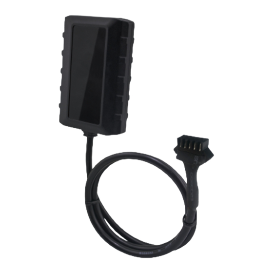
GV57MG User Manual 2. Product Overview 2.1 Check Parts List Before starting, check whether all the following items have been included with your GV57MG. If anything is missing, please contact your supplier. Figure 1. Appearance of GV57MG 2.2 Parts List Name... -
Page 9: Interface Definition
GV57MG User Manual GV57MG USB Cable 0.5M(Optional) Table 3: GV57MG Parts List 2.3 Interface Definition GV57MG has a 5-Pin cable. The figure of the 5-Pin cable is shown below. Figure 2. GV57MG 5-Pin Cable Index Description Color Remark Orange Digital Input1,negative trigger... -
Page 10: Getting Started
GV57MG User Manual 3. Getting Started 3.1 Installing a SIM Card Step 1: Remove the top cover (ensure the device is not powered unplug the 5-Pin cable and turn off the battery) . Note: Waterproof equipment. Don’t disassemble repeatedly. Step 2: Put the SIM card into the SIM card holder. Press down on the SIM card slightly to make it slide into the slot. - Page 11 GV57MG User Manual Step 3: Place the top cover on the bottom cover, and tighten both covers until they snap.Make sure that the seal ring is in place and there is no obvious gap between covers and seal ring. Step 4: Turn over the device and tighten the screws with screw cushion.
-
Page 12: Uart Interface
GV57MG User Manual 3.2 UART Interface There is a UART interface on GV57MG used to connect to GV57MG UART Cable 0.5M. UART is used for configuration. The UART interface and USB interface use the same physical interface. 3.3 USB Interface GV57MG has one USB interface which uses the same physical interface as UART interface. -
Page 13: Power Connection
GV57MG User Manual 3.4 Power Connection PWR (VCC, Red) / GND (Black) are the power input pins. The input voltage range for this device is from 8V to 32V. The device is designed to be installed in vehicles that operate on 12V/24V vehicle without the need for external transformers. -
Page 14: Digital Input
Open Table 6: Electrical Characteristics of Digital Input Figure 5.Typical Digital Input Connection 3.7 Digital Output OUT (Brown) is a digital outputon GV57MG. It is of open drain type and the maximum drain current is 150mA. TRACGV57MGUM001 - 13 -... - Page 15 GV57MG User Manual Figure 6. Internal Driver Circuit for Digital Output Index Description Remark Enable <1.5V @ 150mA Disable Open drain Table 7: Electrical Characteristics of Digital Output Figure 7.Typical Connection with a Relay Note: 1. Many modern relays come with a fly backdiode pre-installed internal to the relay itself.
-
Page 16: Led Status
GV57MG User Manual 3.8 LED Status GV57MG has two status LEDs that are CELL LED and GNSS LED. Figure 8. GV57MG LEDs on the Case Device Status LED Status CELL The device is searching cellular network. Fast flashing The device has been registered to cellular... -
Page 17: Motion Sensor Direction
GV57MG User Manual 3.9 Motion Sensor Direction GV57MG has an internal 3-axis accelerometer supporting motion detection. The following shows the directions of the motion sensor. The z-axis points vertically inward. Figure 9. Motion Sensor Direction TRACGV57MGUM001 - 16 -... -
Page 18: Troubleshooting And Safety Information
Do not put the device in overheated, too humid place, and avoid exposure to direct sunlight. Too high temperature will damage the device or even cause battery explosion. Do not use GV57MG on airplane or near medical equipment. TRACGV57MGUM001 - 17 -... - Page 19 This device complies with part 15 of the FCC rules . Operation is subject to the following two conditions: (1) this device may not cause harmful interference, and (2) this device must accept any interference received, including interference that may cause undesired operation. NOTE: The manufacturer is not responsible for any radio or TV interference caused by unauthorized modifications to this equipment.
Need help?
Do you have a question about the GV57MG and is the answer not in the manual?
Questions and answers
I have just purchased a GV57MG V2 with 2 tags. Please explain what is the purpose of the button and indictor on the BLE tags?
The indicator on the Queclink GV57MG shows the device's status. A fast flashing green LED means it is searching for a cellular network, while a slow flashing green LED means it is registered to the network. A red LED indicates GNSS status: ON means GNSS is off, OFF means GNSS has location info, fast flashing means it’s searching for a signal, and slow flashing means there is a GNSS data error. The context does not mention a button or its purpose.
This answer is automatically generated