Table of Contents
Advertisement
Advertisement
Table of Contents

Subscribe to Our Youtube Channel
Related Manuals for Maple Systems Blue Series


Summary of Contents for Maple Systems Blue Series
- Page 2 COPYRIGHT NOTICE This manual is a publication of Maple Systems, Inc., and is provided for use by its customers only. The contents of the manual are copyrighted by Maple Systems, Inc.; reproduction in whole or in part, for use other than in support of Maple Systems equipment, is prohibited without the specific written permission of Maple Systems.
-
Page 3: Table Of Contents
Opening a Screen ....63 What is a Blue Series OIT? ..4 Creating a New Screen ..66 List of Features. - Page 4 Blue Series Installation & Operation Manual Creating Analog Meters ... . . 115 Creating Trend Displays ... . . 117 Creating XY Plots .
-
Page 5: Introduction - Welcome
Introduction Introduction - Welcome Welcome to the Maple Systems’ BLU300 Series of Operator Interface Terminals (OITs). The BLU300 is a low cost, easy-to-use graphical operator interface with membrane-style keypad. The BLU300 connects to programmable logic controllers (PLCs) to provide the human-machine interface in industrial applications. The BLU300 Series has several features not found in other low cost OITs. -
Page 6: What You Need
PLC. Please locate the sheet that corresponds to your PLC on our website. Maple Systems manufactures custom cables of any length to connect the BLU300 to Communication Cable your PLC. Please visit our website for a complete list of available cables or build your... -
Page 7: Oit Basics
The Maple Systems BLU300 Series OITs are graphics-based membrane-style keypad OITs. Before we get any further into the operation of these OITs, it is necessary to define some terms that will be used throughout this manual. -
Page 8: What Is A Blue Series Oit
Finally, the Blue Series is powered by a 25 MHz, 16-bit microprocessor with 256K Byte of flash memory and 32K Byte of RAM. The Blue Series is designed for industrial environments and carries a NEMA 4 rating as well as CE compliance for noise immunity and emissions. -
Page 9: List Of Features
List of Features The next chapter will guide you through the creation of your first project. Before you proceed, you may wish to read this brief list of some of the features offered in the Blue Series OIT. Icon Bit Lamp Creates a graphics object to reflect the current status of a PLC bit. - Page 10 Blue Series Installation & Operation Manual Rectangle Draws a rectangle or square outline. (outline) Circle Draws a circle or ellipse outline. (outline) Curve Draws a curve. Chord Draws a chord outline. (outline) Sector Draws a sector outline. (outline) Polygon Draws a polygon shape.
-
Page 11: Chapter 1 - Installation Of Oits
NEMA Rating The Blue Series OITs are rated for NEMA 4/12 or IP65 installations. This means that when the OIT is properly mounted to a panel or other enclosure, the front enclosure of the OIT will provide protection to the inside of the panel from splashing water, wind blown dust, rain, or hose-directed water. -
Page 12: Safety Precautions
Blue Series Installation & Operation Manual Safety Precautions Please observe the following precautions when installing the Blue Series OIT. Failure to comply with these restrictions could result in loss of life, serious personal injury, or equipment damage. Warning: Do not operate the OIT in areas subject to explosion due to flammable gases, vapors, or dusts. -
Page 13: Control Panel Design Guidelines
The control panel should be connected to a good, high-integrity earth ground both for safety considerations and shielding purposes. Maple Systems cannot overemphasize the importance of good grounding. If you fail to use good grounding procedures during installation, sporadic malfunction of the OIT may occur: •... -
Page 14: Power Supply Selection
Blue Series Installation & Operation Manual If the control panel is made of a non-conductive material, it is essential that you connect the chassis ground terminal of the OIT to a clean earth ground point located close to the panel. - Page 15 F. Connect the power cable shield wire to the OIT power terminal’s chassis ground input. Route the power cable to the OIT power supply. The power cable should not be any longer than necessary. Install the power supply wires as follows (with colors shown for Maple Systems cable P/N 6030-0009): Color...
-
Page 16: Connect The Oit To The Plc
Connect the OIT to the PLC Each PLC supported by Maple Systems has its own wiring requirements. Maple Systems offers OIT-to-PLC communication cables for most PLCs that are built to any length and tested for high reliability. Most cables are available for next-day shipment from Maple Systems. -
Page 17: Panel Preparation
Installation of OITs Port 1, PC[RS-232]/PLC[RS232]/PLC[RS422], has a shielded male DB9P connector Tighten all screws Control panel Port 1 PLC[RS-232]/[RS-422] BATTERY PLC/ PC[RS-232] Host Port 2 PLC[RS-485] Earth EXTENSION PORT Attach earth ground wire (if included on cable) 2-Wire RS485 Communication cable specific for Shielded power cable the PLC/Host;... -
Page 18: Mount The Oit To The Panel
Blue Series Installation & Operation Manual Mount the OIT to the Panel Installing the Screws on the OIT STEPS: Prepare the four screw clamps for the BLU300 by inserting the clamps into the slots of the back enclosure as show in the illustration above. - Page 19 Installation of OITs COM port on your PC. See the figure below for serial port pin assignments and the next two figures for connecting the BLU300 series to a PC. BLU300 SERIES CONFIGURATION CABLE 4-40 x 1/2 Retainer 4-40 x 1/2 Retainer Screw, 2 places Screw, 2 places DE9S Connector...
-
Page 20: Factory Configuration
Blue Series Installation & Operation Manual Maple Systems OIT programming cable, BATTERY Shielded DB9P P/N 7431-0102 male connector (If mouse is using Com 1, use Com2) EXTENSION PORT Com2 Com1 BLU300M Shield Printer (outside ferrite core) OIT Power Supply Output... -
Page 21: Chapter 2 - Creating Your First Project
Setting the PC COM Port used by BlueLeaf BlueLeaf is initially configured to use Com Port 1: In Windows, click the Start button. Select Programs. Select Maple Systems. Select BlueLeaf. The BlueLeaf application software will activate. Open an existing project, or create a new one. Click the menu, then click PC-HMI Settings. -
Page 22: Starting Blueleaf
Download your project to the Blue Series OIT. Maple Systems produces PLC communications cables that will connect the OIT to most of the PLCs available. The cables can be manufactured to any length you require. A listing of all the PLC cables Maple Systems offers, along with cable drawings, can be found on our website. -
Page 23: Creating A Sample Project
Creating Your First Project The following illustration shows the various sections of BlueLeaf. Creating a Sample Project This section walks you through the creation of a BlueLeaf project named Sample.mpl. Once downloaded to the OIT, this basic configuration allows the OIT to connect to the PLC, display a startup screen, and display a screen containing one PLC register monitor when a switch on the startup screen is pressed. -
Page 24: Selecting The Plc
Blue Series Installation & Operation Manual Selecting the PLC Whenever you begin a new project, you need to select which PLC you intend to use and the name of the project: To select a PLC and start a new project: Click the menu, then click New. - Page 25 Creating Your First Project Click in the content box and type This is the Startup Screen!. Split the sentence into two lines as shown: 10. Click OK. 11. On the main screen of BlueLeaf, you will see the text object with small white boxes around the perimeter.
- Page 26 Blue Series Installation & Operation Manual 4. Double-click on the function key object to display the dialog box: EDIT BUTTON OBJECT Click the Type pull-down box and select Screen Jump. In the Screen Jump Setting frame box, select 1 from the Screen No. pull-down box.
-
Page 27: Creating A Second Screen
Creating Your First Project 14. Move the mouse cursor over the function key box and click/drag to move on Screen 0 as shown: Creating a Second Screen We will configure Screen #1 to display a PLC register. You will also create an increment and decrement key to change the value in the PLC Register. - Page 28 Blue Series Installation & Operation Manual the size. Simply move the mouse cursor over the appropriate white box until the mouse cursor changes to a double-arrow symbol, then click and drag to change the size. To create an increment key on Screen#1 From the menu, click Function Key.
- Page 29 Creating Your First Project Use the mouse cursor to click and drag the second F1 key to the right of the first F1 key. Double-click on the second increment key. The Edit Button Object dialog box appears: Enter the data as shown above (for more details on using the Function Key object, consult Chapter 9: Using the Function Keys ) Click the Show States Table button: Click on the Label entry and type F2.
-
Page 30: Finishing Up
Blue Series Installation & Operation Manual The following illustration shows how Screen #1 looks: You have now done your part in creating this sample project. It is now time for BlueLeaf to do its part. Finishing Up There are still a few steps, which must be completed before you can test your first project. In this section, you will: •... - Page 31 Creating Your First Project Displaying your project on the OIT 1. Press the key on the OIT to exit the download screen. 2. Disconnect the OIT from the computer, and connect to your PLC. 3. Press the F5 function key to move the blinking cursor to 5.EXIT&RUN. 4.
-
Page 32: Chapter 3 - Using Blueleaf Software
Using BlueLeaf Software Chapter 3 - Using BlueLeaf Software Overview The BlueLeaf software is used to create a project file that can be downloaded into the BLU300 operator interface terminal. This chapter shows you how to maneuver around BlueLeaf easily. This will pave the way for actually creating graphics objects in later chapters. -
Page 33: Managing Projects
Blue Series Installation & Operation Manual Managing Projects Like most Windows ® application software, BlueLeaf will open, save, close, and print files using the standard windows format. Opening, Editing Projects To create a new project On the menu, click New or click the New icon in the Standard toolbar. The New Project dialog... -
Page 34: System Screens
Using BlueLeaf Software To open an existing project On the Menu, click Open or click the Open icon in the Standard toolbar. The Open dialog box FILE appears: Click on the project file you intend to open. Click Open. The main screen of BlueLeaf appears with the initial screen of the project displayed. To close a project On the menu, click Close. -
Page 35: Editing And Creating Screen Objects
Blue Series Installation & Operation Manual Edit the text on the different screens as desired, by double clicking the text and modifying the attributes in the Edit Text Object dialog box. (Consult Chapter 6 - Creating Graphics Objects...Using Text for more information) To save changes made to system screens, on FILE menu, click Save, or click the Save icon in the Standard toolbar. - Page 36 Using BlueLeaf Software To display the Screen Manager On the menu, click Screen Manager or click the Screen Manager icon on the Standard TOOLS toolbar. The Screen Manager appears: The Screen Manager allows quick screen selection for editing. You can also create a new screen, delete an existing one, or insert a new screen between pre-existing screens.
-
Page 37: Basic Editing Commands
Blue Series Installation & Operation Manual To create a new screen On the menu, click Add New Screen or click the Add New Screen icon on the Standard toolbar. EDIT A new screen appears in the work area of BlueLeaf. - Page 38 Using BlueLeaf Software Move the mouse cursor to the lower right corner of the highlighted objects. Notice that a rectangle is formed as you do this. In this example, move the mouse to the right and below Make Same Size. Release the mouse button.
- Page 39 Blue Series Installation & Operation Manual On the EDIT menu, click Multi-copy, or right click the mouse anywhere on the work area to display a popup window, and then click Multi-copy. The multi-copy dialog box appears: For Horizontal copies, check the box next to Horizontal numbers and enter the number of copies, 1-50, in the area next to the Horizontal numbers.
- Page 40 Using BlueLeaf Software To resize a graphic object Objects such as Bit Lamps, Word Lamps, and bitmaps cannot be resized. 1. Move the mouse cursor over one of the small white squares. The cursor changes to a double-arrow icon to indicate that it is in resizing mode. Click and drag the mouse to resize the object.
- Page 41 Blue Series Installation & Operation Manual Using the nudge top , bottom , left , and right commands Select one object or a group of objects in the work area of BlueLeaf. Click the appropriate icon from the Alignment toolbar. The object(s) will move in that direction by one pixel.
- Page 42 Using BlueLeaf Software Using the align right command Select the objects you wish to align. For this example, select the three rectangle objects of Screen_1. Click the appropriate icon from the Alignment toolbar. From the menu, click Undo to put the objects back in their original position. EDIT Using the align up command Select the objects you wish to align.
- Page 43 Blue Series Installation & Operation Manual Click the appropriate icon from the Alignment toolbar. From the menu, click Undo to put the objects back in their original position. EDIT 1010-0300, Rev 02...
- Page 44 Using BlueLeaf Software Changing PLC Type BlueLeaf Software supports the ability to change the PLC Type to an existing project. To Change PLC Type 1. From the menu, select Set Device Type. The Set Device Type dialog box appears. TOOLS 1010-0300, Rev 02...
- Page 45 Blue Series Installation & Operation Manual Use the Target Machine dialog box to select which PLC you want to use. The window will show a list of supported registers for the PLC chosen. Click OK for the changes to take effect, and close the window.
- Page 46 Using BlueLeaf Software Open the file that contains the firmware update. Click Open File. The Open File dialog box appears. Select the file and click Open. The file date and time of creation should appear after selecting the file. 10. Start Firmware Update. Click Start Burn. 11.
- Page 47 Blue Series Installation & Operation Manual BLU300 Security BlueLeaf Software supports the ability to deny or grant access to different objects on screens. Security is achieved by assigning user levels to each object that needs to be protected. To Configure User Levels/Passwords From the menu, select User-level/Password set.
- Page 48 Using BlueLeaf Software To Assign User/Security Levels User Levels can be assigned to objects that require operator interface, such as function keys. Start by placing a function key on a screen. From the menu, select Function Key. Select a OBJECTS place on the screen to place the key (left click mouse to place object.) The Edit Button Object dialog box appears: For more details on using the Function Key Object, consult Chapter 9: Using the Function Keys.
-
Page 49: Chapter 4 - Basic Operation Of The Blu300
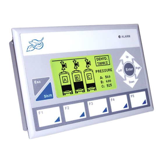
Basic Operation of the BLU300 Chapter 4 - Basic Operation of the BLU300 Overview The BLU300 operator interface terminal is a graphics-based display with a membrane-style keypad. Below is an outline of the features of the BLU300: Front Outline of BLU300 Hardware Description Component... -
Page 50: Using The Left, Right, Top And Down Keys48
Local Setup Menus The Blue Series has local setup menus that are used to configure the OIT and to allow upload/download of project files. BlueLeaf also has a setup menu that can be configured. The table below provides a brief list of the setup menus and their function: 1. -
Page 51: Downloading A Project To The Blu300
Basic Operation of the BLU300 Once the local setup menu is accessed, the following should be displayed on the BLU300: Downloading a Project to the BLU300 To download a project to the BLU300, follow these steps: Access the as shown above. LOCAL SETUP MENU Connect the BLU300 RS-232 port to your computer using the configuration cable (Maple P/N 7431-0102) -
Page 52: Blu300S
Blue Series Installation & Operation Manual In BlueLeaf, click File…Close to close any project that is currently opened. If you upload a project from the OIT while an existing project is open, it will overwrite that project. Click Options…PC-HMI Comm Settings to select the PC’s com port and parameters. -
Page 53: Hmi Setup Menu For The Blu300
Basic Operation of the BLU300 HMI Setup Menu for the BLU300 menu allows you to change many of the hardware settings of the BLU300 OIT: HMI SETUP Most of the following settings can be changed through the Tools...HMI default settings. See page 53 for more information on HMI Default Settings. - Page 54 Blue Series Installation & Operation Manual The blinking cursor will highlight the options for the particular parameter you have selected. Use the right/left arrow keys to select one of the options. Press the key to select the new option. A ENTER brief message Setup complete will appear, indicating that the new option has been saved.
- Page 55 Basic Operation of the BLU300 To configure the System Parameter Setting for Backlight control: From the Global Settings menu, select System Parameter Setting. The System Parameter Editor dialog box appears: In the PLC/Controller Address frame, enter the PLC register address, or click the PLC/Controller Address button to display the address dialog box.
- Page 56 Blue Series Installation & Operation Manual Press the key. The blinking cursor will now highlight the options for that parameter. ENTER Use the right/left arrow keys to switch between the options or digits for that parameter. Use the function keys to change each digit value (ex. F1 =1, F5 =5, Shift F1 =6, Shift F10 =0).
- Page 57 Basic Operation of the BLU300 To enable/disable buzzer using BlueLeaf software From the TOOLS menu, click HMI Default Settings. The HMI Default Setting dialog box appears. In the Functional Settings frame, check the Enable Buzzer Setting box. Click OK. Then download project to the OIT. Setting the Menu Language The BLU300 Local Setup menus and the BlueLeaf configuration software can be configured in English, Simplified Chinese or Traditional Chinese.
- Page 58 Blue Series Installation & Operation Manual 2 7 G H I J K 3 8 L M N O P 4 9 Q R S T U 5 0 V W X Y Z Scroll through each list of characters for each function key by continuously pressing that key.
-
Page 59: Hmi Configuration Settings
Basic Operation of the BLU300 Selecting the Startup Display The Startup Display setting allows you to enable or disable the herald screen as seen below: When enabled, this screen briefly appears whenever the OIT is powered up. Then the first screen of your project is displayed. - Page 60 Blue Series Installation & Operation Manual To configure the HMI default settings On the TOOLS menu, click HMI Default Settings. The HMI Default Setting dialog appears. In the Select Default COM Port area, select either COM1 (RS232) for RS232 communication or COM2 (RS485/RS422) for RS485/RS422 communication.
- Page 61 Basic Operation of the BLU300 To configure HMI-PLC Communication Settings On the TOOLS menu, click HMI-PLC Comm. Settings. The HMI-PLC Communications Settings dialog appears. In the Baud Rate area, use the drop down menu to select 115200, 57600, 38400, 19200, 9600 or 4800 bps.
- Page 62 Blue Series Installation & Operation Manual b. Choose Timed Interval, then enter, or use the up/down arrow keys, to select an interval from 1-200 minutes that will save the project at that interval. Click OK to accept changes or Cancel to cancel any changes made.
- Page 63 Basic Operation of the BLU300 To configure the Power On Macro Setting On the GLOBAL SETTINGS menu click Power on Macro Setting. The Power On Macro Setting dialog appears. In the PLC/Controller Address area, select either bit for coils, or value for registers. In the PLC/Controller Address frame, enter the PLC register address, or click the PLC/Controller address button to display the address dialog box.
- Page 64 Blue Series Installation & Operation Manual 1010-0300, Rev 02...
-
Page 65: Chapter 5- Creating And Displaying Screens
An operator interface terminal wouldn’t be very useful if all of the information to be displayed could only be placed onto one screen. Therefore, most OITs have multiple screens that can be used to display information. The Maple Systems Blue Series is capable of storing up to 999 screens (actual limit is determined by memory requirements of each screen), giving you maximum flexibility in designing your operator interface. - Page 66 Blue Series Installation & Operation Manual To open a screen From the menu, select Screen Manager. Or click the Screen Manager icon from the Standard TOOLS Toolbar. The Screen Manager dialog box appears: Click on the screen you wish to open, and then click OK. You can also open the screen by double-clicking it.
- Page 67 Creating and Displaying Screens Let’s look at the Screen Manager again, using the sample project. The Screen Manager lists all of the screens currently created for the project. You will notice that in the sample project, ten screens have been created. Each screen is listed with a screen number and title. The screen title is the name that you assign to the screen in the Screen Manager.
-
Page 68: Creating A New Screen
Blue Series Installation & Operation Manual To close a screen You will notice three small icons located in the upper right hand corner of each screen: the minimize icon , the maximize icon , and the close icon . To close a screen, click the close icon associated with that screen. -
Page 69: Deleting A Screen
Creating and Displaying Screens Deleting a Screen To delete a screen From the menu, select Screen Manager. Or click the Screen Manager icon from the Standard TOOLS Toolbar. The Screen Manager dialog box appears. Highlight the screen that you wish to delete. Click the Delete command. -
Page 70: Writing The Screen Number To A Plc Register
Blue Series Installation & Operation Manual Use the up/down arrow keys to move the blinking cursor to 8. Start-up display. Press the ENTER key. From the START-UP DISPLAY menu, use the up/down arrow keys to move the blinking cursor to 1. -
Page 71: How To Display Screens
Creating and Displaying Screens How to Display Screens Screens are displayed on the BLU300 using the following methods: • Configuring the OIT to continuously monitor a PLC register or coil using the ‘Jump To Screen’ feature • Configuring a function key to display a new screen •... - Page 72 Blue Series Installation & Operation Manual In the PLC/Controller Address frame, enter the PLC coil or register address. Or click the PLC/Controller Address button to display the Edit PLC/Controller Address dialog box: In the reference address area, click the pull-down box to select the target PLC memory area. Use the numeric keypad to enter the specific PLC memory address.
-
Page 73: Displaying Screens Using Function
Creating and Displaying Screens 4x1 > 5: if value in register 4x1 is greater > Greater than condition screen than 5, activate 4x1 < 5: if value in register 4x1 is smaller < Less than condition screen than 5, activate 4x1 >= 5: if value in register 4x1 is greater >= Greater than or equal to... - Page 74 Blue Series Installation & Operation Manual To configure the System Parameter Setting to display a screen From the Global Settings menu, select System Parameter Setting. The System Parameter Editor dialog appears. In the PLC/Controller Address frame, enter the PLC/register address, or click the PLC/Controller Address button to display the address dialog.
-
Page 75: Chapter 6 - Creating Graphics Objects
Creating Graphic Objects Chapter 6 - Creating Graphics Objects Drawing Objects To display any graphic objects on the OIT screen, you must either create them using the drawing tools included with BlueLeaf software, import them as bitmaps from another applications program, or select from the many choices available in the graphic libraries included with BlueLeaf software. - Page 76 Blue Series Installation & Operation Manual While holding the left button on the mouse, drag the black outline box to the point where you wish to mark the opposite end of the rectangle. Release the left button of the mouse to display the new rectangle.
- Page 77 Creating Graphic Objects start at the lower left corner start at the upper right corner start at the lower right corner Click and drag on the small white boxes (the mouse cursor will change to a double arrow) to change the width or height of the curve.
- Page 78 Blue Series Installation & Operation Manual start at the lower right corner Click and drag on the small white boxes (the mouse cursor will change to a double arrow) to change the width or height of the chord. Click and drag anywhere within the border of the new chord to move it to a new location.
- Page 79 Creating Graphic Objects Double-click the final side to complete the polygon. A series of small white square blocks will appear around the boundaries of the polygon. Click and drag on the small white boxes (the mouse cursor will change to a double arrow) to change the width or height of the polygon.
- Page 80 Blue Series Installation & Operation Manual Right Left Select Direction: to change the orientation of the numbers: Normal Reverse The Major Ticks: box and Minor Ticks: box are used to configure the number of tick marks you need. 10. The Max: and Min: determine the number range that is displayed.
-
Page 81: Using Text
Creating Graphic Objects To change the measure used, double-click the object: Type: Length Area Volume Weight Velocity Temperature KM 2 ° C ° F CM 2 CM 3 Symbol: MILE 2 MILE MILE FT 2 FT 2 INCH 2 INCH 3 INCH The size of the Unit of Measure cannot be varied. - Page 82 Blue Series Installation & Operation Manual To add text, double-click the object. The Edit Text Object dialog box appears: Select the font size and type by clicking the Font button. Enter the text in the content box: Press the ENTER key to begin new lines.
-
Page 83: Predefined Bitmaps
Creating Graphic Objects To quickly edit the text box You can edit the text of a text box by clicking on the text object and then making changes in the Text Input box located on the Text/Graphic Toolbar. You can also change the font by clicking on the font button in the Text/Graphic Toolbar. -
Page 84: Creating Custom Bitmaps
Blue Series Installation & Operation Manual Double-click on any of the libraries to open that folder and display the bitmaps within that library: Click on any of the bitmap files and use the Preview Box to view the bitmap. To select the bitmap, click Open. -
Page 85: Chapter 7 - Using Dynamic Objects
Using Dynamic Objects Chapter 7 - Using Dynamic Objects BlueLeaf software includes several active graphics objects or ‘parts’ that are used to represent data that is stored in the PLC or controller. The data represented can be single bit coils, 16-bit, or 32-bit registers. The data can be represented as numbers, ASCII characters, or as graphic shapes or bitmaps. -
Page 86: The Word Lamp Object
Blue Series Installation & Operation Manual PLC/Controller Address button to display the Edit PLC/Controller Address dialog box: In the Reference Address area, click the pull-down box to select the target PLC memory area. Use the numeric keypad to enter the specific PLC memory address. Select the PLC Network Address (if applicable) and HMI communications port. - Page 87 Using Dynamic Objects and left click the mouse to place a Word Lamp object on the screen. Move the mouse cursor over the Word Lamp object and double-click the Word Lamp object. The Edit Word Lamp Object dialog box appears. In the PLC/Controller Address frame, enter the PLC coil or controller address.
-
Page 88: The Multi-State Bitmap W/Label
Blue Series Installation & Operation Manual In the Format: box, use the pull-down box to select the format that determines how the OIT interprets the value in the PLC register. Select from: Size Format Range Description (Bits) Unsigned 0 to 65535... -
Page 89: The Multi-State Bitmap W/Label Object
Using Dynamic Objects The Multi-State Bitmap w/Label Object The Multi-State Bitmap w/Label Object is very similar to the Bit Lamp and the Word Lamp objects. It is also used to read values from a PLC coil or register but there are three additional features: •... - Page 90 Blue Series Installation & Operation Manual In the PLC/Controller Address frame, enter the PLC coil or register address. Or click the PLC/Controller Address button to display the Edit PLC/Controller Address dialog box: Check the Memory Area box. Click the pull-down box to select the target PLC memory area. Use the numeric keypad to enter the specific PLC memory address.
-
Page 91: The Clock Display Object
Using Dynamic Objects 10. In the Label: box, you can enter text that is displayed when the state is valid. The length of the text string is limited to the size and type of font you have selected and the width of the OIT screen. For example, for font MS Serif 6, a maximum of 32 characters can be used. - Page 92 Blue Series Installation & Operation Manual the Clock Display object and double-click the Clock Display object. The Edit Clock Display Object dialog box appears. In the Time Source frame, select HMI or PLC as the source of the clock information. If HMI is selected, the frame to the right will change to Write to…...
- Page 93 Using Dynamic Objects Click the PLC/Controller Address button to display the Edit PLC/Controller Address dialog box: In the reference address area, click the pull-down box to select the target PLC memory area. Use the numeric keypad to enter the specific PLC memory address. Select the PLC Network Address (if applicable) and HMI communications port.
-
Page 94: The Dynamic Messages Object
Blue Series Installation & Operation Manual The Dynamic Messages Object The Dynamic Messages Object is used to display predefined text messages depending upon the value read from a PLC register or coil. This feature can be used to display alarm messages or other information to the plant floor operator. - Page 95 Using Dynamic Objects Special Effect Description Normal the message is displayed with no special effects. the entire message blinks on and off (regardless of Blink state every 2 sec) the entire message will scroll across the area set aside for the dynamic message according to four Scroll settings: Bottom to top, Top to bottom, Right to left, and Left to right.
- Page 96 Blue Series Installation & Operation Manual state, as shown in the example above. You can also click the Range Calculator button to display the Range Calculator: 13. The Range Calculator is a tool to help you easily determine the ranges. By setting the minimum value to be represented (lower boundary) and maximum value to be represented (upper boundary), the calculator will evenly divide the range for each state.
-
Page 97: Chapter 8 - Entering/Displaying Numeric And Ascii Characters
Entering & Displaying Numeric/ASCII Characters Chapter 8 - Entering/Displaying Numeric and ASCII Characters The BlueLeaf software includes two objects that are used to represent numeric or ASCII character data that is stored in the PLC. The data represented can be single bit coils, 16-bit or 32-bit registers. The data can be displayed as numbers or ASCII characters. - Page 98 Blue Series Installation & Operation Manual In the PLC/Controller Address frame, enter the PLC coil or controller address. Or click the PLC/Controller Address button to display the Edit PLC/Controller Address dialog box: In the reference address area, click the pull-down box to select the target PLC memory area. Use the numeric keypad to enter the specific PLC memory address.
-
Page 99: The Numeric Input Object
Entering & Displaying Numeric/ASCII Characters Therefore, it is the responsibility of the HMI programmer to ensure the HMI settings are correct for the PLC range to be used. The Frame Outline attribute box allows you to enclose the data in a box. Select from- None, Single, Double, Thick, Dot, or Dotted Line. - Page 100 Blue Series Installation & Operation Manual Write attribute box, or click the PLC/Controller Address button to display the Edit PLC/Controller Address dialog box: In the Reference Address area, click the pull-down box to select the target PLC memory area. Use the numeric keypad to enter the specific PLC memory address.
- Page 101 Entering & Displaying Numeric/ASCII Characters In the Size attribute box, select either 16 bits or 32 bits. The Int. Number and Dec. Number attribute boxes are used to specify the number of digits you want displayed before/after a decimal point. For example, if you are writing to a 16-bit PLC register using unsigned format and have Int.Number =3 and Dec.Number =2, then the BLU300 will allow you to write a five digit number with the three leftmost digits placed to the left of a decimal point and the two rightmost digits placed to the right of the decimal point.
-
Page 102: Displaying And Using The Numeric Entry Screen
Blue Series Installation & Operation Manual numeric keypad to enter the specific PLC memory address. Select the PLC Network Address (if applicable) and HMI communications port. Click Enter to go back to prior dialog box. 16. Select either Before Writing or After Writing. This determines whether the coil is written to before the new value is written to the PLC register or immediately after when the Enter key is pressed. - Page 103 Entering & Displaying Numeric/ASCII Characters The screen you create should look like the following when finished: To create a sample numeric entry screen Start a new project file, with the PLC driver of your choice. The initial screen (Screen 0) is displayed in the work area of BlueLeaf.
- Page 104 Blue Series Installation & Operation Manual Click Tools…Write Project to BLU300. On the BLU300, power up the OIT and hold down the ESC key during power-up. The BLU300 will eventually beep and display the following setup screen: Press the F1 key to move the block cursor to 1. Read from PC, and then press the ENTER key on the BLU300.
- Page 105 Entering & Displaying Numeric/ASCII Characters The function keys F1-F5 have two numbers associated with each key: Shift Shift 15. Press the function key associated with the number you wish to use. For Shift Key numbers (6-0), simply press the SHIFT key until the inverse video character ‘S’ appears on the BLU300 screen, then press the function key.
-
Page 106: Chapter 9 - Using The Function Keys
Chapter 9 - Using The Function Keys The Blue Series has membrane-style keypads that can be configured to act as momentary switches, push-on/off keys, display screens or used to enter numeric data or ASCII characters into PLC registers. This chapter shows how to configure the Function Keys. - Page 107 Blue Series Installation & Operation Manual Function Option Description Force On Sets the target PLC coil when pressed. Force Off Clears the target PLC coil when pressed. Sets the target PLC coil when pressed. For most PLC communications drivers, the Pulse On performs the same Pulse On function as the Force On (see the PLC driver’s Controller...
-
Page 108: The Function Key Editors
Using the Function Keys depending upon the value of the PLC coil or register used in the Write address frame; however, this does not mean that the object will continuously read the value of this address to determine the current state. - Page 109 Blue Series Installation & Operation Manual To create a Global Function Key From the menu, click Function Key Editor. The Global Function Key Editor GLOBAL SETTINGS dialog box appears: Click on the function key (F1 thru F10, up, down, left r right) that you wish to configure. Note: F6-F10 correspond to shift F1-F5 keys.
-
Page 110: Using The Local Function Key Editor
Using the Function Keys To configure the up and down keys to be used as function keys, you must first redefine these keys. To redefine the up and down keys, Click Tools...Function Key Setting...Redefine Up/Down Key Click Yes in the Confirm Window. Once these keys are redefined, they will no longer function as Page Up/Page Down keys Using the Local Function Key Editor As with the Global Function Key Editor, the Local Function Key Editor configures a function key to do the following:... - Page 111 Blue Series Installation & Operation Manual To create a Local Function Key From the menu, click Function Key Editor. The Local Function Key LOCAL SCREEN SETTINGS Editor dialog box appears: Click on the Function Key (F1 thru F10, up, down, left, or right) that you wish to configure. Note: F6-F10 correspond to shift F1-F5 keys.
- Page 112 Using the Function Keys To configure the up and down keys to be used as function keys, you must first redefine these keys. To redefine the up and down keys, Click Tools...Function Key Setting...Redefine Up/Down Key Click Yes in the Confirm Window. Once these keys are redefined, they will no longer function as Page Up/Page Down keys 1010-0300, Rev 02...
- Page 113 Blue Series Installation & Operation Manual 1010-0300, Rev 02...
-
Page 114: Plots
Bar Graphs and Meters Chapter 10 - Bar Graphs, Meters, Trends and XY Plots This chapter focuses on four special graphic objects that can be used to display PLC data registers. You read in Chapter 7 how to use text and bitmaps to represent the data in PLC registers as states. You also read in Chapter 8 how to use alphanumeric data fields to display the contents of PLC registers as either numbers or ASCII characters. - Page 115 Blue Series Installation & Operation Manual Graph and left click the mouse to place a Bar Graph object on the screen. Move the mouse cursor over the Bar Graph object and double-click the Bar Graph. The Edit Bar Graph Object dialog box appears: In the PLC/Controller Address frame, enter the PLC coil or controller address.
-
Page 116: Creating Analog Meters
Bar Graphs and Meters In the Format attribute box, select the format type you wish to use. The options are: Size Format Range Description (Bits) Unsigned 0 to 65535 unsigned 16 bit format 0 to 4294967295 unsigned 32 bit format Signed 32768 to +32767 signed 16 bit format... - Page 117 Blue Series Installation & Operation Manual To create an Analog Meter Object From the menu, click Analog Meter. Or click the Analog Meter icon in the Objects OBJECTS toolbar. The mouse cursor changes to a crosshair. Select the location on the screen to place the Analog Meter and left click the mouse to place an Analog Meter object on the screen.
-
Page 118: Creating Trend Displays
Bar Graphs and Meters 0000 to 9999 BCD 16 bit format The Int. Number and Dec. Number attribute boxes are used to specify the number of digits you want displayed before/after a decimal point. For example, suppose you are monitoring a 16-bit PLC register using unsigned format with Min = 0 and Max =1000. - Page 119 Blue Series Installation & Operation Manual In the PLC/Controller Address frame, enter the PLC coil or controller address.. Or, click the PLC Controller Address button to display the Edit PLC/Controller Address dialog: Click the pull-down box to select the target PLC memory area. Use the numeric keypad to enter the specific PLC memory address.
-
Page 120: Creating Xy Plots
Bar Graphs and Meters Example: Vertical Max: 10 Vertical Min: 0 4x100 = 4 4x101 = 2 4x103 = 8 4x105 = 4 4x107 = 7 With the above values entered, the trend should appear as on the right. Creating XY Plots The XY plot object is used to represent 16-bit registers as a plot of connecting points. - Page 121 Blue Series Installation & Operation Manual In the PLC/Controller Address frame, enter the PLC coil or controller address. Or click the PLC/Controller Address button to display the Edit PLC/Controller Address dialog: In the Reference Address area, click the pull-down box to select the target PLC memory area. Use the numeric keypad to enter the specific PLC memory address.
- Page 122 Bar Graphs and Meters 4x105=6 (X3) 4x106=1 (Y3) 4x107=9 (X4) 4x108=6 (Y4) With the above values entered, the XY plot should appear as on the right. 1010-0300, Rev 02...
-
Page 123: Chapter 11 - Using Alarms
Using Alarms Chapter 11 - Using Alarms BlueLeaf includes two alarm features: the alarm LED and the alarm buzzer, which are used to indicate problems that may occur in the control system. Used in conjunction with the Dynamic Message object, the alarm feature can highlight alerts and display them on the OIT screen as warnings. - Page 124 Blue Series Installation & Operation Manual Size Format Range Description (Bits) Unsigned 0 to 65535 unsigned 16 bit format 0 to 4294967295 unsigned 32 bit format Signed 32768 to +32767 signed 16 bit format -2147483648 to +2147483647 signed 32 bit format...
-
Page 125: Monitoring Alarms With The Alarm Buzzer Editor
Using Alarms In the PLC/Controller Address frame, enter the PLC coil or register address. Or click the PLC/Controller Address button to display the Edit PLC/Controller Address dialog box: In the Reference Address area, click the pull-down box to select the target PLC memory area. Use the numeric keypad to enter the specific PLC memory address. - Page 126 Blue Series Installation & Operation Manual When the Alarm Buzzer Editor is selected, the Alarm Buzzer Editor dialog box appears: First select either Bit or Value to determine if the Alarm Buzzer will read from a PLC coil or a PLC register (16 or 32 bit).
-
Page 127: Displaying Alarms Using The Dynamic Message Object
Using Alarms Trigger Description Example Condition 4x1 = 5: if value in register 4x1 is equal to Equal condition 5, activate LED. 4x1 > 5: if value in register 4x1 is greater > Greater than condition than 5, activate LED. 4x1 <... - Page 128 Blue Series Installation & Operation Manual Using the Dynamic Message object to display Alarm messages Let’s go through an example to illustrate how to configure an Alarm LED, an Alarm Buzzer, and a Dynamic Message object to alert a plant floor operator of alarm conditions:...
- Page 129 Using Alarms Next, use the Global Alarm LED Editor to assign the alarm LED to the same PLC register as is used for the dynamic message, with the following settings: Finally, use the Global Alarm Buzzer Editor to configure the OIT buzzer as follows: 1010-0300, Rev 02...
- Page 130 Blue Series Installation & Operation Manual When you have finished, the startup screen should look like the following: 1010-0300, Rev 02...
- Page 131 Using Alarms Now download your project to the BLU300 Series OIT. Enter the value 1 into the PLC register you are using for the alarm (in this example, 4x1). The following should be displayed on the OIT, with the Alarm LED on and the buzzer pulsing: Now enter the value 10: To remove the alarm, enter value 11.
-
Page 132: Chapter 12 - Using A Memory Stick
Using a Memory Stick Chapter 12 - Using a Memory Stick The BLU300 Series supports the ability to quickly download/upload a project using a memory stick called the Program Copy Card (PCC). The PCC (Maple P/N 7902-0001) is an optional accessory for the BLU300 which reduces the time required to download a project into the BLU300: PCC (Maple P/N 7902-0001) Copying a project from the BLU300 to the PCC... -
Page 133: Copying A Project From The Pcc To The Blu300
Blue Series Installation & Operation Manual Apply power to the BLU300. The OIT will display the following: Press the ENTER key on the OIT. The OIT will download the project to the memory stick, then display the following: Remove power from the BLU300 and remove the memory stick. - Page 134 Using a Memory Stick Apply power to the BLU300. The OIT will display the following: Press the ENTER key on the OIT. The OIT will download the project from the memory stick, then display the following: Remove power from the BLU300 and remove the memory stick. Power up the BLU300.
-
Page 135: Appendix A - Specifications
Specifications Appendix A - Specifications BLU300M: Display Type – 3” STN Graphic LCD w/back light Resolution – 128 x 64 pixels Display Size (WxH) – 2.64” [67mm] x 1.26”[32mm] Back light – LED back light with up to 50,000 hour life span Ten step contrast adjustment Hardware Microprocessor –Hitachi H8/3064F 25 MHz... -
Page 136: Communications
Blue Series Installation & Operation Manual Communications One RS-232 serial port (DE9P) used for OIT configuration and controller communications One RS-485 two-wire serial port (Molex input) for controller communications Baud rates from 4800 to 115200 Point-to-point serial communications for all protocols (network support for Modbus protocol) -
Page 137: Bar Graphs
Specifications Bar Graphs Define the direction- up, down, right, or left Adjustable min/max range Scale object for tick marks and numeric labels Meters Two formats- 300 degree or 360 degree Scale with major/minor tick marks Numeric labels with four font sizes Adjustable min/max range PLC Register Control Decimal, Signed, Hex, and BCD representation... -
Page 138: Cutout
Dimensional Outlines & Panel Cutout Appendix B - Dimensional Outlines & Panel Cutout 1010-0300, Rev 02... - Page 139 ..71 Blue Series OIT, features ....5 downloading a project ....49 BlueLeaf software, exiting.
- Page 140 Blue Series Installation & Operation Manual new screen ..... 66 nudge......39 factory configuration.
- Page 141 Index displaying27 creating20 saving26 System Clock Setting ....60 project, closing....31 System Parameter Setting .
Need help?
Do you have a question about the Blue Series and is the answer not in the manual?
Questions and answers