Table of Contents
Advertisement
Technical Services: Tel: (800) 381-9312 / Fax: (800) 791-5500
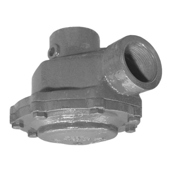
Model DV-3 Deluge Valve, Automatic Resetting
2-1/2 Inch (DN65), 175 psi (12,1 bar)
Thread x Thread or Groove x Groove
Table of
Contents
General Description . . 1
Technical Data . . . . . 3
Valve Trim . . . . . . . . 3
Wet Pilot Actuation . . . 4
Dry Pilot Actuation . . . 8
Operating Principles . . 15
Installation . . . . . . . . 17
Procedures . . . . . . . 17
Care and Maintenance . 18
Limited Warranty . . . . 20
Ordering Procedure . . 20
Page 1 of 20
General
Description
The 2-1/2 inch (DN65), Model DV-3
Automatic Resetting Deluge Valve is a
quick opening, hydraulically operated
differential type valve designed for fire
protection system service. It is used as
an "automatic water control valve" in
deluge, preaction, and special types of
fire protection systems such as foam-
water and double interlock. The DV-3
Valve also provides for actuation of fire
alarms upon system operation.
. . . 12
The automatic resetting feature of the
DV-3 provides for easy, external reset-
ting, without having to open a valve
handhole cover to manually reposition
a clapper and latch mechanism.
Operation of a DV-3 Valve is provided
by an actuation (detection) system that
is separate from the normally dry sys-
tem piping. Trim configuration options
for automatic operation of the DV-3
include wet pilot actuation, dry pilot
actuation, and electric actuation. Trim
arrangements also provide for local
emergency (manual) release of the
DV-3 Valves.
The compact and easily installed trim
arrangements have been designed so
that the DV-3 Valve may be installed
"flow left" or "flow right"
The Model DV-3 Deluge Valve is a
redesignation for the Gem Model
F445.
MARCH, 2006
WARNING
The Model DV-3 Deluge Valve de-
scribed herein must be installed and
maintained in compliance with this
document, as well as with the applica-
ble standards of the National Fire Pro-
tection Association, in addition to the
standards of any other authorities hav-
ing jurisdiction. Failure to do so may
impair the integrity of these devices.
The owner is responsible for maintain-
ing their fire protection system and de-
vices in proper operating condition.
The installing contractor or manufac-
turer should be contacted relative to
any questions.
TFP1350
Advertisement
Table of Contents

Related Manuals for Tyco DV-3


Summary of Contents for Tyco DV-3
-
Page 1: Table Of Contents
Installation ..17 handhole cover to manually reposition a clapper and latch mechanism. Valve Setting Operation of a DV-3 Valve is provided Procedures ..17 WARNING by an actuation (detection) system that... - Page 2 ..10 Facing Retainer . . . See (b) Retainer Screw ..See (b) Thread x Groove Adapter (Optional) FIGURE 1 2-1/2 INCH (DN65) MODEL DV-3 DELUGE VALVE — ASSEMBLY —...
-
Page 3: Technical Data
Cover are ductile iron. The Diaphragm GRAPH A and Facing are EPDM. The Diaphragm 2-1/2 INCH (DN65) MODEL DV-3 DELUGE VALVE Ring and Center Valve are are bronze, — NOMINAL PRESSURE LOSS VERSUS FLOW — and the Seat Ring is brass. The Facing retainer is brass. -
Page 4: Wet Pilot Actuation
TD1382. used for wet pilot lines. The maximum height of a wet pilot line above the DV-3 Valve must not exceed the limitations given in Graph B as a function of the minimum water supply pressure to the DV-3 Valve and the length of the pilot line to the most re- mote pilot sprinkler. - Page 5 10 (3,05) (1,4) (2,6) (4,1) (5,5) (6,9) (8,3) (9,7) (11,0) (12,1) NOTE: IF SUPPLY PRESSURE IS VARIABLE, SUPPLY PRESSURE, ASSUME MINIMUM EXPECTED VALUE. PSI (BAR) GRAPH B 2-1/2 INCH (DN65) MODEL DV-3 DELUGE VALVE — WET PILOT DESIGN CRITERIA —...
- Page 6 (Standard Order). Route all Tubing to Drip Funnel. FIGURE 3 2-1/2 INCH (DN65) MODEL DV-3 DELUGE VALVES — EXPLODED VIEW OF WET PILOT ACTUATION TRIM (52-445-2-101) — (Refer to Figure 12 to see the factory assembled trim segments, as well as functional callouts of the trim components)
- Page 7 (400,1 mm) MINIMUM CLEARANCE, ADDITIONAL 2" (500 mm) RECOMMENDED. 6-1/4" 5-5/8" 1-5/8" (158,8 mm) (142,9 mm) (41,3 mm) LEFT VIEW FRONT VIEW FIGURE 4 2-1/2 INCH (DN65) MODEL DV-3 DELUGE VALVE — WET PILOT ACTUATION / NOMINAL INSTALLATION DIMENSIONS —...
-
Page 8: Dry Pilot Actuation
Connection at the most remote loca- Graph C shows the “minimum pilot line vent proper operation. Also, introduc- tion from the DV-3 Valve. Nominal in- service pressure” as a function of the tion of moisture into the pilot lines ex- stallation dimensions for Dry Pilot Ac- water supply pressure. - Page 9 WATER SUPPLY PRESSURE IN PSI requirement shown in Graph C. GRAPH C • Fire alarm setting at approximately 2-1/2 INCH (DN65) MODEL DV-3 DELUGE VALVE 15 psi (1,0 bar) below the minimum — DRY PILOT LINE PRESSURE REQUIREMENTS — pilot line service pressure require- ment shown in Graph C.
- Page 10 (Standard Order). Route all Tubing to Drip Funnel. FIGURE 6 2-1/2 INCH (DN65) MODEL DV-3 DELUGE VALVES — EXPLODED VIEW OF DRY PILOT ACTUATION TRIM (52-445-2-102)— (Refer to Figure 12 to see the factory assembled trim segments, as well as functional callouts of the trim components)
- Page 11 (400,1 mm) MINIMUM CLEARANCE, ADDITIONAL 2" (500 mm) RECOMMENDED. 6-1/4" 5-5/8" 1-5/8" (158,8 mm) (142,9 mm) (41,3 mm) LEFT VIEW FRONT VIEW FIGURE 7 2-1/2 INCH (DN65) MODEL DV-3 DELUGE VALVE — DRY PILOT ACTUATION / NOMINAL INSTALLATION DIMENSIONS —...
-
Page 12: Electric Actuation
Diaphragm Chamber Information on the various types of of the DV-3 Valve, and the force differ- separately ordered Solenoid Valves ential holding the Center Valve As- that may be used with this trim pack-... - Page 13 (Standard Order). Route all Tubing to Drip Funnel. FIGURE 9 2-1/2 INCH (DN65) MODEL DV-3 DELUGE VALVES — EXPLODED VIEW OF ELECTRIC ACTUATION TRIM (52-445-2-103) — (Refer to Figure 12 to see the factory assembled trim segments, as well as functional callouts of the trim components)
- Page 14 15-3/4" (400,1 mm) MINIMUM CLEARANCE, ADDITIONAL 2" (500 mm) RECOMMENDED. 6-1/4" 5-5/8" 1-5/8" (158,8 mm) (142,9 mm) (41,3 mm) LEFT VIEW FRONT VIEW FIGURE 10 2-1/2 INCH (DN65) MODEL DV-3 DELUGE VALVE — ELECTRIC ACTUATION / NOMINAL INSTALLATION DIMENSIONS —...
-
Page 15: Operating Principles
The nomi- in order for the DV-3 to remain open. nal trip ratio is 2.5 to 1, i.e., the DV-3 Valve operates (opens) when the pres- sure in the Diaphragm Chamber is re- duced to approximately 40 percent of the water supply pressure. - Page 16 Port Identification. FUNNEL Route all Tubing to Drip Funnel. 1-1/4 INCH NPT CONNECTION TO DRAIN FIGURE 12 2-1/2 INCH (DN65) MODEL DV-3 DELUGE VALVE —FACTORY PREASSEMBLED TRIM SEGMENTS— —FUNCTIONAL CALLOUTS FOR TRIM COMPONENTS— — ASSEMBLY PROCEDURE FOR VALVE TRIM —...
-
Page 17: Installation
Step 11. The Low Pressure Alarm Step 2. Close the Main Control Valve, The DV-3 Valve must be installed in a Switch for Dry Pilot Actuation is to be and if the system is equipped with Dry readily visible and accessible location. -
Page 18: Care And Maintenance
If there are no 3, 4, and 5, if water must be prevented nection to or from the diaphragm leaks, the DV-3 Valve is ready to be from flowing beyond the riser. chamber or, a leak in the diaphragm... - Page 19 If there are no tions to energize the solenoid valve. leaks, the DV-3 Valve is ready to be Step 4. Verify that the flow of water placed in service and the Main Control from the Solenoid Valve drain connec- Valve must then be fully opened.
-
Page 20: Limited Warranty
This warranty will apply to the full ex- tent permitted by law. The invalidity, in whole or part, of any portion of this warranty will not affect the remainder. TYCO FIRE & BUILDING PRODUCTS, 451 North Cannon Avenue, Lansdale, Pennsylvania 19446...
Need help?
Do you have a question about the DV-3 and is the answer not in the manual?
Questions and answers