Table of Contents
Advertisement
Quick Links
Technical Services: Tel: (800) 381-9312 / Fax: (800) 791-5500
Model DV-1 Deluge Valve, External Resetting
4 and 6 Inch (DN100 and DN150)
Flange x Flange or Flange x Groove
Table of
Contents
General Description . . 1
Technical Data . . . . . 3
Valve Trim . . . . . . . . 4
Wet Pilot Actuation . . . 4
Dry Pilot Actuation . . . 8
Operating Principles . . 15
Installation . . . . . . . . 15
Procedures . . . . . . . 15
Care and Maintenance . 18
Limited Warranty . . . . 19
Ordering Procedure . . 20
Page 1 of 20
General
Description
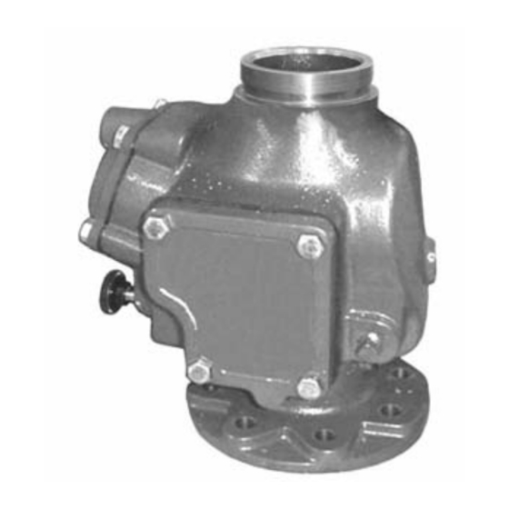
The 4 and 6 inch (DN100 and DN150),
Model DV-1 External Resetting Del-
uge Valves are differential latch type
valves designed for fire protection sys-
tem service. They are used as "auto-
matic water control valves" in deluge,
preaction, and special types of fire pro-
tection systems such as foam-water
and double interlock. The DV-1 Valves
also provide for actuation of fire alarms
upon system operation.
. . . 12
The external resetting feature of the
DV-1 Valve provides for easy resetting
of a deluge or preaction system, with-
out having to open a valve handhole
cover to manually reposition a clapper
and latch mechanism. Simply de-
pressing a plunger at the left side of
the DV-1 Valve allows the clapper and
latch to reset.
Operation of a DV-1 Valve is provided
by an actuation (detection) system that
is separate from the normally dry sys-
tem piping. Trim configuration options
for automatic operation of the DV-1
include wet pilot actuation, dry pilot
actuation, and electric actuation. Trim
arrangements also provide for local
emergency (manual) release of the
DV-1 Valves.
The Model DV-1 Deluge Valves de-
scribed herein must be installed and
maintained in compliance with this
document, as well as with the applica-
ble standards of the National Fire Pro-
tection Association, in addition to the
standards of any other authorities hav-
ing jurisdiction. Failure to do so may
impair the integrity of these devices.
The owner is responsible for maintain-
ing their fire protection system and de-
vices in proper operating condition.
The installing contractor or manufac-
turer should be contacted relative to
any questions.
MARCH, 2006
WARNING
TFP1330
Advertisement
Table of Contents

Related Manuals for Tyco DV-1


Summary of Contents for Tyco DV-1
-
Page 1: Table Of Contents
Simply de- Procedures ..15 pressing a plunger at the left side of the DV-1 Valve allows the clapper and Care and Maintenance . 18 latch to reset. Operation of a DV-1 Valve is provided Limited Warranty . - Page 2 6" (DN150) Model DV-1 F x F Deluge Valve shown for reference. 10, 25 FIGURE 1 4 and 6 INCH (DN100 and DN150) MODEL DV-1 DELUGE VALVE — ASSEMBLY — Nominal Dimensions in Inches and (mm) Dim. A 4" (DN100) Valve 6"...
-
Page 3: Technical Data
GRAPH A with NPT threaded ports will readily accept the trim arrangements detailed 4 and 6 INCH (DN100 and DN150) MODEL DV-1 DELUGE VALVE in Figures 3, 6, or 9. — NOMINAL PRESSURE LOSS VERSUS FLOW — Components for the DV-1 Valve are shown in Figure 1. -
Page 4: Valve Trim
1/2 inch the following items: pipe from the DV-1 Valve to the loca- (DN15) Schedule 40 steel pipe. The tion. Then, using Graph B, determine pilot line is connected to the “Wet Pilot the minimum system supply pressure •... - Page 5 (4,1) (5,5) (6,9) (8,3) (9,7) (11,0) (12,1) NOTE: IF SUPPLY PRESSURE IS VARIABLE, SUPPLY PRESSURE, ASSUME MINIMUM EXPECTED VALUE. PSI (BAR) GRAPH B 4 and 6 INCH (DN100 and DN150) MODEL DV-1 DELUGE VALVE — WET PILOT DESIGN CRITERIA —...
- Page 6 15 CH Funnel. FIGURE 3 4 and 6 INCH (DN100 and DN150) MODEL DV-1 DELUGE VALVES — EXPLODED VIEW OF WET PILOT ACTUATION TRIM (52-470-2-101) — (Refer to Figure 12 to see the factory assembled trim segments, as well as functional callouts of the trim components)
- Page 7 CONNECTING TRIM FxG) (FIELD FABRICATED) MAIN 1-1/4" NPT 2" NPT CONTROL DRAIN DRAIN VALVE LEFT VIEW FRONT VIEW FIGURE 4 4 and 6 INCH (DN100 and DN150) MODEL DV-1 DELUGE VALVE — WET PILOT ACTUATION / NOMINAL INSTALLATION DIMENSIONS —...
-
Page 8: Dry Pilot Actuation
• Model AMD-1 Air Maintenance De- Connection at the most remote loca- used for dry pilot lines. tion from the DV-1 Valve. Nominal in- vice (pressure reducing type), refer Supervision of the pressure in the dry stallation dimensions for Dry Pilot Ac- to Technical Data Sheet TFP1221. - Page 9 SUPPLY CONTROL VALVE OPEN) (NORMALLY OPEN) WATER SUPPLY FIGURE 5 SYSTEM SCHEMATIC — DRY PILOT ACTUATION WATER SUPPLY PRESSURE IN PSI GRAPH C 4 and 6 INCH (DN100 and DN150) MODEL DV-1 DELUGE VALVE — DRY PILOT LINE PRESSURE REQUIREMENTS —...
- Page 10 ..Funnel. FIGURE 6 4 and 6 INCH (DN100 and DN150) MODEL DV-1 DELUGE VALVES — EXPLODED VIEW OF DRY PILOT ACTUATION TRIM (52-470-2-102)— (Refer to Figure 12 to see the factory assembled trim segments, as well as functional callouts of the trim components)
- Page 11 CONNECTING TRIM FxG) (FIELD FABRICATED) MAIN 1-1/4" NPT 2" NPT CONTROL DRAIN DRAIN VALVE LEFT VIEW FRONT VIEW FIGURE 7 4 and 6 INCH (DN100 and DN150) MODEL DV-1 DELUGE VALVE — DRY PILOT ACTUATION / NOMINAL INSTALLATION DIMENSIONS —...
-
Page 12: Electric Actuation
Valve opens resulting in a rapid pres- sions for the Electric Actuation Trim sure drop in the Diaphragm Chamber are shown in Figure 10. of the DV-1 Valve, and the force differ- ential applied through the Clapper NOTE latch which holds the Clapper down in... - Page 13 ..Funnel. FIGURE 9 4 and 6 INCH (DN100 and DN150) MODEL DV-1 DELUGE VALVES — EXPLODED VIEW OF ELECTRIC ACTUATION TRIM (52-470-2-103) — (Refer to Figure 12 to see the factory assembled trim segments, as well as functional callouts of the trim components)
- Page 14 (FxF or CONNECTING TRIM FxG) (FIELD FABRICATED) MAIN 1-1/4" NPT 2" NPT CONTROL DRAIN DRAIN VALVE LEFT VIEW FRONT VIEW FIGURE 10 4 and 6 INCH (DN100 and DN150) MODEL DV-1 DELUGE VALVE — ELECTRIC ACTUATION / NOMINAL INSTALLATION DIMENSIONS —...
-
Page 15: Operating Principles
FIGURE 11D SYSTEM DRAIN POSITION RESETTING VALVE FIGURE 11 4 and 6 INCH (DN100 and DN150) MODEL DV-1 DELUGE VALVE — SET AND OPEN POSITIONS — ized through the trim connections from sure then forces the Clapper open per- Operating the inlet side of the system’s main con-... -
Page 16: Installation
FROM WATER TRIM SUPPLY FIGURE 12 4 and 6 INCH (DN100 and DN150) MODEL DV-1 DELUGE VALVES —FACTORY PREASSEMBLED TRIM SEGMENTS— —FUNCTIONAL CALLOUTS FOR TRIM COMPONENTS— — ASSEMBLY PROCEDURE FOR VALVE TRIM — wet pilot lines must be maintained at a... -
Page 17: Valve Setting
Valve Setting strainer basket. The Strainer may be DV-1 Valve (Ref. Figures 4, 7, and 10). flushed out by momentarily opening Procedure Step 8. An Inspector’s Test Connec-... -
Page 18: Care And Maintenance
If there are no from flowing beyond the riser. for example, to a leak in a piping con- leaks, the DV-1 Valve is ready to be • Wet Pilot Actuation — Open the nection to or from the diaphragm... -
Page 19: Limited Warranty
If there are no Products manufactured by Tyco Fire & leaks, the DV-1 Valve is ready to be Building Products (TFBP) are war- Step 4. Verify that the flow of water... -
Page 20: Ordering Procedure
P/N 52-328-2-001 Model MC-1 (Gav.) Manual Control Stations for remote wet or dry pilot actuation ... . P/N 52-289-2-001 TYCO FIRE & BUILDING PRODUCTS, 451 North Cannon Avenue, Lansdale, Pennsylvania 19446...
Need help?
Do you have a question about the DV-1 and is the answer not in the manual?
Questions and answers