Tyco DV-5 Manual
Hide thumbs
Also See for DV-5:
- Manual (32 pages) ,
- Instruction manual (17 pages) ,
- General description manual (14 pages)
Table of Contents
Advertisement
Quick Links
DV-5 Deluge Valves, Diaphragm Style
FM Approved European Conformity Valve Trim
General
Description
The DV-5 Deluge Valves are diaphragm
type valves used as "automatic water
control valves" in deluge fire protection
systems. When properly trimmed, the
DV-5 Valves are also able to provide
actuation of fire alarms upon system
operation.
The diaphragm style design of the DV-5
Valve allows external resetting, pro-
viding for easy resetting of a deluge
system without having to open a valve
handhole cover to manually reposition
a clapper and/or latch mechanism.
Simply re-pressurizing the diaphragm
chamber resets the valve.
The DV-5 also features internal and
external coating of the valve to provide
corrosion resistance. The external
corrosion resistance of the RILSAN
coating permits the use of the DV-5 in
corrosive atmospheres associated with
many types of industrial processing
plants and outdoor installations.
NOTICE
The DV-5 Deluge Valves described
herein must be installed and main-
tained in compliance with this docu-
ment, as well as with the applicable
standards of the Approval agency, in
addition to the standards of any other
authorities having jurisdiction. Failure
to do so may impair the performance
of these devices.
The owner is responsible for main-
taining their fire protection system
and devices in proper operating con-
dition. Contact the installing contrac-
tor or product manufacturer with any
questions.
Technical
Data
Approvals
FM Approved when trimmed as
described in this technical data sheet
for European Conformity applications.
Page 1 of 26
End Connections Available and Weights
End Connection
Inlet
Outlet
DN40
Thread
Thread
4,1 kg
Groove
Groove
3,6 kg
Flange
Groove
N/A
Flange
Flange
N/A
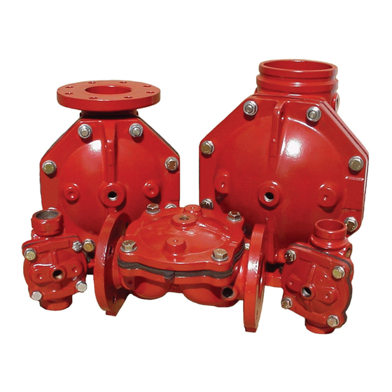
DV-5 Deluge Valve
Components for the DN40 thru DN200
DV-5 Deluge Valves are shown in
Figure 1. The DV-5 Valves are for verti-
cal installations, and they are rated for
use at a maximum service pressure of
17,2 bar.
The take-out dimensions are shown in
Figure 2, and the flanged connections
are available drilled per ANSI, ISO, AS,
and JIS specifications (Ref. Table A).
DECEMBER 2016
Worldwide
www.tyco-fire.com
Contacts
Nominal Valve Size
DN50
DN80
DN100
5,4 kg
N/A
N/A
4,5 kg
14,1 kg
27,7 kg
N/A
17,7 kg
33,6 kg
N/A
21,3 kg
36,3 kg
The DV-5 Valves are provided with
ISO 7-1 threaded ports that will
readily accept the trim arrangements
described in this technical data sheet.
Pressure Loss
Refer to Graph A
DN150
DN200
N/A
N/A
44,9 kg
68,1 kg
48,5 kg
77,8 kg
52,3 kg
87,5 kg
TFP1335
Advertisement
Table of Contents

Related Manuals for Tyco DV-5


Summary of Contents for Tyco DV-5
- Page 1 The DV-5 also features internal and external coating of the valve to provide corrosion resistance. The external corrosion resistance of the RILSAN coating permits the use of the DV-5 in corrosive atmospheres associated with many types of industrial processing plants and outdoor installations.
- Page 2 295,0 23,0 292,0 22,0 1. Flange end DN40 and DN50 DV-5 Valves are not offered 2. Same drilling as for B16.5 (Class 150) and B16.42 (Class 250) 3. Same drilling as for BS 4504 Section 3.2 (PN10) and DIN 2532 (PN10) 4.
-
Page 3: Materials Of Construction
65-45-12 closed against the water supply Handhole Cover pressure. RILSAN polyamide 11 coated ductile When the DV-5 Valve is set for service, iron per ASTM A536-77, Grade the Diaphragm Chamber is pressurized 65-45-12 460 mm through the trim connections from the Diaphragm inlet side of the system’s stop valve. - Page 4 DRAIN ITS SEATED DRAIN POSTION PORT DIAPHRAGM CHAMBER VALVE OPEN TO WATERWAY ATMOSPHERE MAIN DRAIN PORT WATER SUPPLY SHUT OFF WATER SUPPLY SHUT OFF FIGURE 3C FIGURE 3D SYSTEM DRAIN POSITION RESIDUAL DRAIN POSITION FIGURE 3 DV-5 DELUGE VALVE OPERATION...
- Page 5 At a minimum, it is recommended that (heat detectors) and manual control pressure to the DV-5 Valve for an equiv- internally galvanized pipe and cast iron stations interconnected with minimum alent length (pipe plus fittings) of the fittings be used for wet pilot lines.
- Page 6 3,4 bar and a maximum follows: part of the laboratory approval of the water supply service pressure of 17,2 DV-5 Valves and is necessary for their • Low pressure alarm setting at bar. proper operation. approximately 0,4 bar below the Graph B shows the “minimum pilot line...
- Page 7 The Electric Actuation Trim forms a part • Voltage: 24 VDC dition intended to energize the Sole- of the laboratory approval of the DV-5 noid Valve to open. After the ten minute Valves and is necessary for their proper • Power Consumption: 22 Watts duration, at which point should the operation.
- Page 8 Device be utilized in dry pilot actuation system applications where the dew point must be maintained WATER SUPPLY PRESSURE IN BAR below -29°C. See Technical Data Sheet TFP1241. GRAPH B DV-5 DELUGE VALVE DRY PILOT LINE PRESSURE REQUIREMENTS Maximum Pilot Height, Meters Supply Pressure...
-
Page 9: Installation
Dry Pilot Actuation sections, After verifying the desired pressure The DV-5 Valve must be installed in a must be provided for Wet or Dry Pilot setting, tighten the jam nut. readily visible and accessible location. - Page 10 ......WS00000096; Nickel pl copper tube; 15 x 1mm for DV-5 ..
- Page 11 AP80D4; pipe nipple; stainless steel 316; 1/2" x 80 mm ..WS00000096; Nickel pl copper tube; 15 x 1mm for DV-5 ..AP80E4; pipe nipple; stainless steel 316; 3/4" x 80 mm .
- Page 12 DN15 male x compr.15mm; nickel pl ..... WS00000096; Nickel pl copper tube; 15 x 1mm for DV-5 ..
- Page 13 WS00000007: Copper pipe; 10 x 12 mm; length 900 mm ..ATDMCON; Adapter fitting; brass; WS00000096; Nickel pl copper tube; 15 x 1mm for DV-5 ..thr. DN15 male x compr.15mm; nickel pl .
- Page 14 AP80E4; pipe nipple; stainless steel 316; 3/4" x 80 mm ..WS00000096; Nickel pl copper tube; 15 x 1mm for DV-5 ..ATDDMN; Adapter fitting; brass;...
- Page 15 AP80D4; pipe nipple; stainless steel 316; 1/2" x 80 mm ..WS00000096; Nickel pl copper tube; 15 x 1mm for DV-5 ..AP80E4; pipe nipple; stainless steel 316; 3/4" x 80 mm .
- Page 16 AP80E4; pipe nipple; stainless steel 316; 3/4" x 80 mm ..WS00000096; Nickel pl copper tube; 15 x 1mm for DV-5 ..ATDDMN; Adapter fitting; brass;...
- Page 17 AP60I2; pipe nipple; steel 37.0; male bspt 2"; galvinised ..WS00000096; Nickel pl copper tube; 15 x 1mm for DV-5 ..AP80E4; pipe nipple; stainless steel 316; 3/4" x 80 mm .
- Page 18 WS00000007: Copper pipe; 10 x 12 mm; length 900 mm ..ATDDMN; Adapter fitting; brass; WS00000096; Nickel pl copper tube; 15 x 1mm for DV-5 ..thr. DN15 x DN15 male; nickel pl .
- Page 19 ..AP80D4; pipe nipple; stainless steel 316; 1/2" x 80 mm ..WS00000096; Nickel pl copper tube; 15 x 1mm for DV-5 ..FIGURE 16...
- Page 20 WS00000007: Copper pipe; 10 x 12 mm; length 900 mm ..ATDDMN; Adapter fitting; brass; WS00000096; Nickel pl copper tube; 15 x 1mm for DV-5 ..thr. DN15 x DN15 male; nickel pl .
- Page 21 ..AP80E4; pipe nipple; stainless steel 316; 3/4" x 80 mm ..WS00000096; Nickel pl copper tube; 15 x 1mm for DV-5 ..FIGURE 18...
- Page 22 3. Dimension applies to Dry Pilot Actuation trim only. 4. Dimension applies to all trims. STOP DN15 DIAPHRAGM VALVE CHAMBER SUPPLY CONNECTING TRIM (FIELD FABRICATED) FRONT VIEW RIGHT VIEW FIGURE 19 DV-5 DELUGE VALVE WITH EUROPEAN CONFORMITY TRIM INSTALLATION DIMENSIONS...
- Page 23 After the dis- Automatic Drain Valve (F) to verify that charge of air has stopped, close the it is open and that the DV-5 Valve is vent valves and the Inspector’s Test completely drained. Connection.
-
Page 24: Care And Maintenance
The owner is responsible for the alarm/indications to monitor the water inspection, testing, and maintenance supply pressure. Step 3. Verify that the DV-5 Valve has of their fire protection system and tripped, as indicated by the flow of Waterflow Alarm Test Procedure devices in compliance with this doc- water into the system. - Page 25 TFP1335 Page 25 of 26 Step 3. Verify that the DV-5 Valve has Step 6. Reset the electric detection tripped, as indicated by the flow of system in accordance with the manu- Nominal Torque water into the system. facturer’s instructions to de-energize Valve Sizes the solenoid valve.
-
Page 26: Limited Warranty
V-Ring, or Valve Body. GLOBAL HEADQUARTERS | 1400 Pennbrook Parkway, Lansdale, PA 19446 | Telephone +1-215-362-0700 Copyright © 2016 Tyco Fire Products, LP. All rights reserved. RILSAN is a registered trademark of Arkema, Inc., LOCTITE is a registered trademark of Henkel Corporation... -
Page 27: Appendix A Of Tfp1335 (12/2016) Summary Instructions (If Problems Occur, Consult Full Document) Deluge Valve, Dv-5, Dn40 Thru Dn200, Wet Pilot Actuation
Appendix A of TFP1335 (12/2016) Summary Instructions (If problems occur, consult full document) Deluge Valve, DV-5, DN40 thru DN200, Wet Pilot Actuation Item Description DV-5 Valve Stop Valve Water ow Switch Main Drain Valve System Drain Valve Automatic Drain Valve... -
Page 28: Appendix B Of Tfp1335 (12/2016) Summary Instructions (If Problems Occur, Consult Full Document) Deluge Valve, Dv-5, Dn40 Thru Dn200, Dry Pilot Actuation
Appendix B of TFP1335 (12/2016) Summary Instructions (If problems occur, consult full document) Deluge Valve, DV-5, DN40 thru DN200, Dry Pilot Actuation Item Description DV-5 Valve Stop Valve Water ow Switch Main Drain Valve System Drain Valve Automatic Drain Valve... -
Page 29: Appendix C Of Tfp1335 (12/2016) Summary Instructions (If Problems Occur, Consult Full Document) Deluge Valve, Dv-5, Dn40 Thru Dn200, Electric Actuation
Automatic Drain Valve (F) Alarm Control Valve (H) are open System Drain Valve (E), and all auxil- for leaks. If there are no leaks, the DV-5 iary drains in the system. Close the Valve is ready to be placed in service •...
Need help?
Do you have a question about the DV-5 and is the answer not in the manual?
Questions and answers