Table of Contents
Advertisement
Quick Links
Model RV-1
A
Pilot-Operated
General
Description
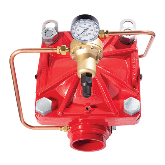
The TYCO Model RV-1
a
Relief Valves, 2 in. to 8 in. (DN50 to
DN200), are factory assembled and
fully trimmed valve arrangements for
relief of excess water pressure. These
valves are typically used to automati-
cally relieve excess pressure in a fire
protection system that utilizes a fire
pump.
The DV-5
Water Control Valve is the
a
central component in the fully-trimmed
assembly. For information on the DV-5
Valve assembly, see Figure 2.
Pilot-controlled, the Model RV-1
maintains a relatively constant system
pressure at the pump discharge as flow
demands change.
The Model RV-1
valve is factory set to
a
approximately 175 psi (12,1 bar). The
valve may be field-set to a nominal
relief "set pressure" of 30 to 250 psi
(2,1 to 17,2 bar).
Features
• O n e - p i e c e,
o n e - m ov i n g - p a r t
diaphragm
• Epoxy-coated interior and exterior
• Accurate pressure control
• In-line service
• No need to bleed trapped air from
the diaphragm chamber
• One pilot valve sub-assembly
that provides for any outlet "set
pressure"; that is; 30 to 250 psi
(2,1 to 17,2 bar)
NOTICE
The TYCO Model RV-1
a
Relief Valves described herein must be
installed and maintained in compliance
with this document and with the appli-
cable standards of the NATIONAL FIRE
PROTECTION ASSOCIATION (NFPA),
in addition to the standards of any
authorities having jurisdiction. Failure
IMPORTANT
Refer to Technical Data Sheet
TFP2300 for warnings pertaining to
regulatory and health information.
Page 1 of 12
All manuals and user guides at all-guides.com
Pressure Relief Valve
to do so may impair the performance
of these devices.
The owner is responsible for main-
taining their fire protection system
Pressure
and devices in proper operating con-
dition. Contact the installing contrac-
tor or product manufacturer with any
questions.
Technical
Data
Approvals
UL Listed
FM Approved
a
Field Relief "Set Pressure" Range
30 to 250 psi (2,1 to 17,2 bar)
Valve
a
Temperature Range
50°F to 175°F (10°C to 80°C)
Maximum System Pressure
300 psi (20,6 bar)
Note: The system pressure is the maximum
pressure the valve is expected to be exposed
to. The valve cannot be set to relieve at any
pressure greater than 250 psi (17,2 bar).
NFPA 20 Recommended
Maximum Flow
2 in. (DN50) . . . . . . . . . . . . . 250 gpm (946 Lpm)
3 in. (DN80) . . . . . . . . . . . . .500 gpm (1893 Lpm)
4 in. (DN100) . . . . . . . . . . .1000 gpm (3785 Lpm)
6 in. (DN150) . . . . . . . . . . 2500 gpm (9462 Lpm)
8 in. (DN200) . . . . . . . . . .5000 gpm (18925 Lpm)
See Graph A for inlet pressure versus flow
characteristics.
End Connections
Flanged end connections are available as
drilled per Table A.
Valve Materials of Construction
See Figure 2
Body
Pressure
Epoxy-coated ductile iron per ASTM
A536-77, Grade 65-45-12
MAY 2021
Worldwide
www.tyco-fire.com
Contacts
Diaphragm Cover
Epoxy-coated, ductile iron per ASTM
A536-77, Grade 65-45-12
Diaphragm
Polyester fabric-reinforced, TEFLON
coated, EPDM rubber per ASTM D2000
Diaphragm Cover Fasteners
Aluminium-zinc coated steel
Trim Materials of Construction
See Figure 6
Pilot Valve
Cast bronze and stainless steel with fabric
reinforced, EPDM rubber per ASTM D2000
diaphragm
Pressure Gauges
3 3/4 in. (95 mm) diameter, UL and FM
listed, 0 to 300 psi (20,7 bar)
Strainer, Tube, and Fittings
Stainless steel
TFP1586
Advertisement
Table of Contents

Related Manuals for Tyco RV-1A


Summary of Contents for Tyco RV-1A
- Page 1 Description The owner is responsible for main- taining their fire protection system The TYCO Model RV-1 Pressure and devices in proper operating con- Relief Valves, 2 in. to 8 in. (DN50 to dition. Contact the installing contrac-...
-
Page 2: Operation
All manuals and user guides at all-guides.com TFP1586 Page 2 of 12 Operation Available End Connections Nominal Valve Size Item The TYCO Model RV-1 Pressure Relief in. (DN) Valve is normally installed on-line in a 2 (50) 3 (80) 4 (100) - Page 3 All manuals and user guides at all-guides.com TFP1586 Page 3 of 12 Nominal Valve Size ANSI Inch (DN) Item Description Qty. 2 (DN50) 3 (DN80) 4 (DN100) 6 (DN150) 8 (DN200) Valve Body Diaphragm 545000020 545000030 545000040 545000060 545000080 Diaphragm Cover Hex Bolt, Short 545100001 545100002...
-
Page 4: Pressure Relief Valve
TFP1586 Page 4 of 12 PRESSURE RELIEF WATER SUPPLY WATER SUPPLY PORT OPEN TO PRESSURE PRESSURE ATMOSPHERE GAUGE PORT FROM RV-1A VALVE THROUGH VALVE UPSTREAM PORT DOWNSTREAM PORT WATER SUPPLY PRESSURE PILOT VALVE SEAT CLOSED FORCE OF SPRING WATER SUPPLY PRESSURE... - Page 5 TFP1586 Page 5 of 12 TURN TURN ADJUSTING ADJUSTING SCREW SCREW COUNTERCLOCKWISE CLOCKWISE TO DECREASE TO INCREASE RV-1A VALVE RV-1A VALVE RELIEF RELIEF PRESSURE PRESSURE LOWER SET PRESSURE RELIEF CONDITION HIGHER SET PRESSURE RELIEF CONDITION GASKET PRESSURE RELIEF DIAPHRAGM PRESSURE...
-
Page 6: Design Considerations
The following items must be consid- adequately inspected in accordance with VALVE SIZE ered and applied accordingly for an NFPA 25. installation that will be using the TYCO The TYCO Model RV-1 Pressure Relief Model RV-1 Pressure Relief Valve: Valve must be installed with the flow •... - Page 7 • Relief set pressure Perform Steps 1 to 4 when placing the the pilot valve (only necessary if valve is TYCO Model RV-1 Pres sure Relief not shut when installed). The tag is not to be removed until after the Valve in service.
- Page 8 All manuals and user guides at all-guides.com TFP1586 Page 8 of 12 Nominal O.D. Nominal Installation Dimensions Valve Pipe Weight Size Size (mm) Inches (kg) (DN) (mm) 2.88 10-3/16 2.80 11.17 5.93 6.53 34.0 (DN50) (60,3) (260) (71,1) (283,7) (150,6) (165,9) (15,4) 3.50...
-
Page 9: Care And Maintenance
Model RV-1 Pressure Step 2. By first using the Long Hex Relief Valve into service, completely The TYCO Model RV-1 Pressure Relief Bolts, support of the Diaphragm Cover unscrew the Adjusting Screw. Then, to Valve requires no lubrication, packing... - Page 10 All manuals and user guides at all-guides.com TFP1586 Page 10 of 12 Problem Cause Solution Valve fails to open 1. Water connections are blocked 1. Dismantle and clean downstream tubing* 2. Pilot adjustment is too high 2. Reset pressure by turning pressure adjusting 3.
-
Page 11: Limited Warranty
Separately ordered Model RV-1A valve Valve, (specify size), (specify part trim accessories. description), P/N (specify, see Figures 2 and 6) Specify: Model RV-1A Sight Glass Kit for AON Approval, P/N 545100111 Note: Sight Glass Kit required for AON Approved applications. Replacement Valve Parts See Figure 6 for replacement parts. - Page 12 All manuals and user guides at all-guides.com TFP1586 Page 12 of 12 1400 Pennbrook Parkway, Lansdale, PA 19446 | Telephone +1-215-362-0700 © 2021 Johnson Controls. All rights reserved. All specifications and other information shown were current as of document revision date and are subject to change without notice. NATIONAL FIRE PROTECTION ASSOCIATION and NFPA are registered trademarks of National Fire Protection Association;...
Need help?
Do you have a question about the RV-1A and is the answer not in the manual?
Questions and answers