Sign In
Upload
Manuals
Brands
Anderson Manuals
Farm Equipment
NWS-660E
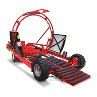
User Manuals: Anderson NWS-660E Round Bale Wrapper
Manuals and User Guides for Anderson NWS-660E Round Bale Wrapper. We have
1
Anderson NWS-660E Round Bale Wrapper manual available for free PDF download: Operator's Manual
Anderson NWS-660E Operator's Manual (120 pages)
Round Bale Wrapper
Brand:
Anderson
| Category:
Farm Equipment
| Size: 6 MB
Table of Contents
Table of Contents
4
1 ANDERSON Limited Warranty
12
One-Year Limited Warranty
12
Documents
12
Problem Resolution
12
Modifications
12
Warranty Exemptions
14
Exclusive Remedy
14
2 Safety
15
Safe Operators
15
Danger Zone
15
Secure Attachment to the Tractor
15
Dangerous Situations
15
Prevention
15
Safe Maintenance and Repair
15
Fuel
15
Hydraulic Oil
16
Traveling Safely on Public Roads
16
End of Operation
16
Figure 2.1 Closing the Fuel Valve
16
3 General Characteristics and Specifications
17
Design
17
Read Me
17
Figure 3.1 Dimensions and Weight
17
4 Moving the Bale Wrapper
18
Short Distances
18
Figure 4.1 Controls
18
Figure 4.2 Engine Throttle Lever
18
Medium Distances
19
Safety Measures
19
Figure 4.3 Draw Bar
19
Figure 4.4 Indicator Decal
19
5 Advice for Producing High-Quality Wrapped Fodder
20
Why Make Fodder Silage
20
Why Make Fodder Silage with Round Bales
20
Why Make Continuous Round Bale Fodder Silage
20
When Is the Best Time to Harvest
20
When Is the Best Time for Baling
21
When Is the Best Time to Produce Continuous Bale Rows
21
6 Beginning Continuous Bale Wrapping
22
Before Beginning
22
Where to Wrap and Store Bales
22
Adjusting the Bale Guides
22
Installing the 1 Plastic Film Roll (Engine Stopped)
22
Figure 6.1 Engine Unit
22
Figure 6.2 Adjusting the Bale Guides
22
Figure 6.3 Brake Pedal
23
Figure 6.4 Roll Support and Stretcher
23
Installing the 2 Plastic Film Roll
24
Start Bale Wrapping
24
Level Position
24
Compression Bales
24
Figure 6.5 Installing the Plastic Film Roll
24
Ground Level
25
The First Wrapped Bale
25
Figure 6.6 Pusher Trigger
25
Hydraulic Brake
26
Direction of the Continuously Wrapped Bale
26
7 Wrapping Settings
27
Adjusting the Number of Plastic Film Layers
27
Adjusting the Distance the Pusher Travels
27
Figure 7.1 Pointer
27
Figure 7.2 Stopper
27
Adjusting the Hoop's Drive Wheel
28
Adjusting the Plastic Film Stretchers
28
Testing the Stretchers
28
Figure 7.3 Hoop Wheel
28
Figure 7.4 Stretcher Spring
28
8 Adjustment Procedures
29
Factory-Made Automatic System: in Case of Problem Check Adjustments
29
Figure 8.1 Start Pedal
29
Figure 8.2 Hoop Lever
29
Figure 8.3 Gap
30
Figure 8.4 Transfer Bar
30
Adjusting the Hoop Release
31
Figure 8.5 Stopper
31
Figure 8.6 Valve
31
Figure 8.7 Hoop Actuator Lever
32
Adjusting the Pusher Trigger
33
Figure 8.8 Pusher Trigger Adjustment Rod
33
Figure 8.9 Pusher Trigger
33
Adjusting the Limit Stop
34
Figure 8.10 Trigger Limit Stop
34
Figure 8.11 Automatic System Spring
34
Figure 8.12 Pusher Plate Ring Pin
35
How to Finish a Continuous Bale Row
35
Figure 8.13 Unloading Post
36
Figure 8.14 Pusher Start Pedal
36
Figure 8.15 Speed Control Lever
36
Variation for Finishing a Continuous Bale Row
36
9 Maintenance and Storage
37
Safety
37
Grease Gun Lubrication
37
Other Lubrication Points
37
Cleaning
41
Preventative Maintenance
41
Storage
41
10 Troubleshooting
42
Breakdown
42
11 Optional Equipment
45
Road Lights
45
Figure 11.1 Road Lights
45
Work Lights
46
Figure 11.2 Work Light
46
Remote Starter
47
Characteristics
47
Programming
47
Malfunction
47
Installing the Remote Starter's IG-D2 Module
47
Figure 11.4 Remote Starter 1
47
Figure 11.5 Remote Starter 2
47
Figure 11.6 Remote Starter Connections
48
Figure 11.7 Remote Starter Connections 2
48
Start up
49
Remote Control
49
Figure 11.8 Remote Starter Connections 3
49
Remote Operation
50
Characteristics
50
Figure 11.9 Direction Valve for Remote Operation
50
Figure 11.10 Remote Control for Remote Operation
51
Figure 11.11 Remote Operation Module
51
Operation
52
Programming
52
Figure 11.12 Electrical Diagram 1
52
Figure 11.3 Electrical Diagram
53
Figure 11.13 Electrical Diagram 2
53
Figure 11.14 Electrical Connections 1
53
Figure 11.15 Electrical Diagram 3
54
Figure 11.16 Electrical Diagram 4
54
Figure 11.17 Electrical Diagram 5
55
Anderson Plastic Detector
56
Figure 11.18 Plastic Detector System
56
Figure 11.19 Detector Parts (Kit A)
57
Figure 11.20 Detector Parts (Kit B)
57
Figure 11.21 Detector Parts (Kit C)
57
12 Hoop
58
Reassembling the Hoop
58
Outer Hoop
58
Inner Hoop
58
Figure 12.1 Outer Hoop
58
Figure 12.2 Inner Hoop
58
Reassembly Instructions for Revolving Hoop
59
Figure 12.3 Revolving Hoop
59
Advertisement
Advertisement
Related Products
Anderson NWS-660
Anderson 680HS
Anderson Double stretcher
Anderson Fusion720
Anderson GB series
Anderson Hay Merger MERGEPRO 1060
Anderson Hay Merger MERGEPRO 915
Anderson IFX720
Anderson Categories
Farm Equipment
Burner
Measuring Instruments
Utility Vehicle
Transmitter
More Anderson Manuals
Login
Sign In
OR
Sign in with Facebook
Sign in with Google
Upload manual
Upload from disk
Upload from URL