Winmate S-Series User Manual
10.1" hmi
Hide thumbs
Also See for S-Series:
- User manual (103 pages) ,
- Quick start manual (40 pages) ,
- User manual (48 pages)
Table of Contents
Advertisement
Quick Links
Advertisement
Table of Contents

Related Manuals for Winmate S-Series


Summary of Contents for Winmate S-Series
- Page 1 10.1" S-Series HMI W10IB3S-PCH2AC-PoE (With LED Light Bar) W10IB3S-PCH2-PoE (Without LED Light Bar) Slim-line User Manual Version 1.5 Document Part Number: 9152111I100M Please read these instructions carefully before using this product, and save this manual for future use...
-
Page 2: Table Of Contents
USER MANUAL CONTENTS CONTENTS PREFACE ...................... - 5 - ABOUT THIS USER MANUAL ................12 CHAPTER1: INTRODUCTION ............... - 15 - 1.1 Product Features ................... - 15 - 1.2 Package Contents .................. - 16 - 1.3 Product Overview ................. - 18 - CHAPTER 2: GETTING STARTED .............. - Page 3 USER MANUAL CONTENTS 3.3.2 Trigger Setting ................ - 30 - 3.3.3 Settings ................... - 31 - 3.3.4 RFID Output Settings .............. - 32 - 2.4.2 Writing Mode ..............- 32 - 3.4 Using Front Camera ................- 33 - 3.4.1 Opening the Camera .............. - 33 - 3.4.2 Shooting Photos ..............
- Page 4 USER MANUAL CONTENTS 6.3.1 Panel Mounting ..............- 80 - 6.3.2 VESA Mounting ............... - 81 - 6.3.3 Front Side Wall Mounting ............- 85 - 6.3.4 Glass Wall Mounting .............. - 87 - CHAPTER 7: TECHNICAL SUPPORT .............. - 89 - 7.1 Software Developer Support ..............
-
Page 5: Preface
USER MANUAL PREFACE PREFACE Copyright Notice No part of this document may be reproduced, copied, translated, or transmitted in any form or by any means, electronic or mechanical, for any purpose, without the prior written permission of the original manufacturer. Trademark Acknowledgement Brand and product names are trademarks or registered trademarks of their respective owners. - Page 6 USER MANUAL PREFACE Warranty Our warranty guarantees that each of its products will be free from material and workmanship defects for a period of one year from the invoice date. If the customer discovers a defect, we will, at his/her option, repair or replace the defective product at no charge to the customer, provide it is returned during the warranty period of one year, with transportation charges prepaid.
- Page 7 USER MANUAL PREFACE Advisory Conventions Four types of advisories are used throughout the user manual to provide helpful information or to alert you to the potential for hardware damage or personal injury. These are Notes, Important, Cautions, and Warnings. The following is an example of each type of advisory.
-
Page 8: Safety Information
USER MANUAL PREFACE Safety Information WARNING! / AVERTISSEMENT! Always completely disconnect the power cord from your chassis whenever you work with the hardware. Do not make connections while the power is on. Sensitive electronic components can be damaged by sudden power surges. Only experienced electronics personnel should open the PC chassis. - Page 9 USER MANUAL PREFACE Safety Precautions For your safety carefully read all the safety instructions before using the device. Keep this user manual for future reference. Always disconnect this equipment from any AC outlet before cleaning. Do not use liquid or spray detergents for cleaning. Use a damp cloth. ...
- Page 10 USER MANUAL PREFACE *Let service personnel to check the equipment in case any of the following problems appear: o The power cord or plug is damaged. o Liquid has penetrated into the equipment. o The equipment does not work well or you cannot get it to work according to the user manual.
-
Page 11: Important Information
USER MANUAL PREFACE Important Information Federal Communications Commission Radio Frequency Interface Statement This device complies with part 15 FCC rules. Operation is subject to the following two conditions: This device may not cause harmful interference. This device must accept any interference received ... -
Page 12: About This User Manual
The documentation set for the 10.1” S-Series HMI provides information for specific user needs, and includes: 10.1” S-Series HMI Quick Start Guide - describes how to get the HMI up and running. 10.1” S-Series HMI User Manual – contains detailed description on how to use the HMI, its components and features. -
Page 14: Chapter1: Introduction
USER MANUAL CHAPTER 1 INTRODUCTION INTRODUCTION This chapter gives you product overview, describes features and hardware specification. You will find all accessories that come with the HMI device in the packing list. Mechanical dimensions and drawings included in this chapter. - 14 -... -
Page 15: Product Features
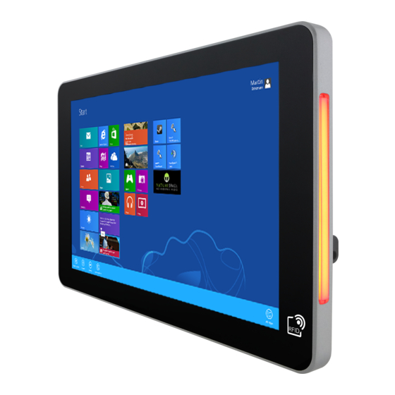
MHz is especially useful in access control applications. S-Series HMI support an exceptional feature - LED light bar. With the help of red, green, blue and orange LED indicators you can see the status of the machine or processes afar. -
Page 16: Package Contents
USER MANUAL CHAPTER 1 INTRODUCTION 1.2 Package Contents Carefully remove the box and unpack your HMI device. Please check if all the items listed below are inside your package. If any of these items are missing or damaged contact us immediately. - Page 17 USER MANUAL CHAPTER 1 INTRODUCTION Package may include optional accessories based on your order: VESA Desk Stand VESA Desk Stand VESA Wall Mount Bracket PCVS-V1 LA-100 LA-106 99KK00A0000E 9B0000000128 9B0000000412 Glass Wall Mount Kit Front Side Wall Mount Right: PCGM-V2R PCFW-V1 Left: PCGM-V2L Right: 99KN00A00010...
-
Page 18: Product Overview
USER MANUAL CHAPTER 1 INTRODUCTION 1.3 Product Overview This section describes physical appearance of the HMI device. Unit: mm Dimensions (W x L x H): 263.48 x 172 x 35.7 mm № Description № Description ① Digital I/O (Optional)* ⑥ RJ-45 (LAN/ PoE)** ②... -
Page 19: Chapter 2: Getting Started
USER MANUAL CHAPTER 2 GETTING STARTED GETTING STARTED This chapter tells you important information on power supply, adapter and precautions tips. Pay attention to power considerations. - 19 -... -
Page 20: Powering On
USER MANUAL CHAPTER 2 GETTING STARTED CHAPTER 2: GETTING STARTED This chapter provides information on how to connect the HMI device to the source of power, connector pinouts and the guideline to turn on/off the HMI device. 2.1 Powering On 2.1.1 AC Adapter Components AC Adapter Power Cord... -
Page 21: Power Considerations
USER MANUAL CHAPTER 2 GETTING STARTED 2.1.2 Power Considerations HMI device operates on external DC power. Use the AC adapter included in the package. CAUTION/ATTENTION Use only the AC adapter (12V/ 50W) included in your package (Rating: Output4.2 A). Using other AC adapters may damage the device. -
Page 22: Connector Pinouts
Maximum Voltage 12.6V Maximum Current 4.2A Voltage 2.2.2 Ethernet Connector The 7” S-Series HMI has two RJ45 connectors that support 10/100/1000 Mbps Ethernet interface for connecting to the internet. Notice that only one RJ45 connector supports PoE function. Pin №... -
Page 23: Usb 2.0 And Usb 3.0 Connector
USER MANUAL CHAPTER 2 GETTING STARTED 2.2.4 USB 2.0 and USB 3.0 Connector Pin № Signal Name Pin № Signal Name USB_D- USB_D+ STDA_SSRX- STDA_SSRX+ GND_DRAIN STDA_SSTX- STDA_SSTX+ USB_D- USB_D+ 2.2.5 Digital I/O Connector Notice that Digital I/O is an optional connector and may not be present in your model. Pin №... -
Page 24: Turning On And Off The Device
USER MANUAL CHAPTER 2 GETTING STARTED Note: A pair of needle nose pliers may be helpful when working with jumpers. If you have any doubts about the best hardware configuration for your application, contact your local distributor or sales representative before you make any changes. - Page 25 USER MANUAL CHAPTER 3 OPERATING THE DEVICE OPERATING THE DEVICE This chapter provides detailed information on how to operate the device. If you have been using touch-screen Panel PCs before, the interface may look familiar. Sections include system settings parameters. - 25 -...
-
Page 26: Chapter 3: Operating The Hmi Device
In this chapter you will find instructions on how to operate the HMI device with Hot Tab. 3.1 Operating System S-series HMI support several versions of Windows OS: Windows 10 IoT, Windows Embedded 8.1 Industry Pro, Windows Embedded 8 Standard, Windows 7 Pro for Embedded Systems, and Windows Embedded Standard 7–... -
Page 27: Utilities
3.2.5 LED Light Bar Notice that LED Light Bar is an optional feature for 10.1” S-Series HMI and may not be present in your device. Tap Light Bar to access the LED light bar control panel, and select Red / Green / Blue/ Orange color to be displayed on the LED Bar. -
Page 28: Performance
USER MANUAL CHAPTER 3 OPERATING THE DEVICE 3.2.6 Performance User can adjust the performance level of the HMI device. There are four options available: Extreme performance Office Document High performance Power Saving 3.2.7 Touch Lock To LOCK touch screen, double-click the Hot Tab icon on the Windows desktop, and tap Touch Lock. -
Page 29: Using Hf Rfid Reader
OPERATING THE DEVICE 3.3 Using HF RFID Reader Notice that HF RFID Reader is an optional feature for 10.1” S-Series HMI and may not be present in your device. HF RFID is commonly used for ticketing, payment, and data transfer applications. -
Page 30: Trigger Setting
USER MANUAL CHAPTER 3 OPERATING THE DEVICE 3.3.2 Trigger Setting Auto Scan The default setting for RFID trigger is Auto Scan. Under this setting, the RFID Reader will always be ready to scan tags. 1. When the RFID tag is detected from RFID antenna, the data will be read automatically. -
Page 31: Settings
USER MANUAL CHAPTER 3 OPERATING THE DEVICE 3.3.3 Settings Sound The Sound check box defines whether a beep sound will come with the data scanning. Output This setting defines the output type of the scanned data. Two options are available: ... -
Page 32: Rfid Output Settings
USER MANUAL CHAPTER 3 OPERATING THE DEVICE Demo Area 3.3.4 RFID Output Settings Select RFID Output Type The default setting for built-in HF RFID Reader is to Read UID. For some applications, user might need to read or write further block data; the drop-down menu under this section can do this change. -
Page 33: Using Front Camera
CHAPTER 3 OPERATING THE DEVICE 3.4 Using Front Camera Notice that 2MP Front Camera is an optional feature for 10.1” S-Series HMI and may not be present in your device. NOTE: You camera screen may differ from the pictures in thus user manual. -
Page 34: Shooting Photos
USER MANUAL CHAPTER 3 OPERATING THE DEVICE Item Description Tap to record videos Video Tap to capture photos Photo Tap to select the destination folder to save captured photos and videos, enable preview, and select picture Settings resolution and quality Tap to close the camera Close Capture Screen... -
Page 35: Recording Videos
USER MANUAL CHAPTER 3 OPERATING THE DEVICE 3.4.3 Recording Videos 1. Open the Camera. 2. Focus on the object. 3. Tap to record the video. The video recording screen appears. 4. Tap to stop recording and return to the camera screen. 5. -
Page 36: Camera Settings
USER MANUAL CHAPTER 3 OPERATING THE DEVICE 3.4.4 Camera Settings 1. Tap to open the setting page. 2. Modify necessary settings. Item Description Check one of the check boxes to show the preview screen right after capturing a photo. • Show Preview: Check this box and enter the preview duration on Close preview after. -
Page 37: How To Enable Watchdog
OPERATING THE DEVICE 3.3 How to Enable Watchdog To enable Watchdog, you need to download Winmate Watchdog utility. Find more information on Watchdog in “Watchdog Guide” that you can download from Winmate Download Center or File Share. Refer to the Ch.7, “Technical Support”... -
Page 38: Chapter 4: Driver Installation
USER MANUAL CHAPTER 4 DRIVER INSTALLATION DRIVER INSTALLATION This chapter describes how to install all necessary drivers. - 38 -... -
Page 39: Installing Chipset Driver
USER MANUAL CHAPTER 4 DRIVER INSTALLATION CHAPTER 4: DRIVER INSTALLATION This chapter provides guideline to driver installations. 4.1 Installing Chipset Driver Step 1 Insert the CD that comes with the motherboard. Open the file document “Chipset Driver” and click “infinst_auto.exe” to install driver. - 39 -... - Page 40 USER MANUAL CHAPTER 4 DRIVER INSTALLATION Step 2 Click Next to continue. Step 3 Click Yes to agree the license terms. - 40 -...
- Page 41 USER MANUAL CHAPTER 4 DRIVER INSTALLATION Step 4 Click Next to install the driver. Step 5 Software setup progress window will appear, click Next to continue. Step 6 Click “Yes, I want to restart this computer now” to finish the installation. - 41 -...
-
Page 42: Installing Graphics Driver
USER MANUAL CHAPTER 4 DRIVER INSTALLATION 4.2 Installing Graphics Driver Step 1 Insert the CD that comes with the motherboard. Open the file document “Graphics Driver” and click Setup to execute the setup. Step 2 Setup Welcome Window will appear, click Next to continue the process. Step 3 Carefully read the license terms and click Yes to agree. -
Page 43: Installing Intel Sideband Fabric Device (Intel Mbi) Driver (Windows 8)
USER MANUAL CHAPTER 4 DRIVER INSTALLATION 4.3 Installing Intel Sideband Fabric Device (Intel MBI) Driver (Windows 8) Step 1 Insert the CD that comes with the motherboard. Open the file document “MBI” and click “Setup.exe” to install the driver. Step 2 Welcome to the setup program window will appear, click Next to start the installation. -
Page 44: Installing Intel Trusted Engine Interface (Intel Txe) Driver
USER MANUAL CHAPTER 4 DRIVER INSTALLATION 4.4 Installing Intel Trusted Engine Interface (Intel TXE) Driver Step 1 Insert the CD that comes with the motherboard. Open the file document “TXE” and click “Setup TXE.exe” to install the driver. Step 2 Welcome to the setup program window will appear, click Next to start the installation. -
Page 45: Installing Intel Network Connections
USER MANUAL CHAPTER 4 DRIVER INSTALLATION 4.5 Installing Intel Network Connections User must confirm the type of operating system is being used before installing Intel Network Connections. Follow the steps below to complete the installation. Step 1 Click “PROWin64.exe” Step 2 Click Yes to start the installation. Step 3 Welcome window will appear, click Next to install the driver. -
Page 46: Installing Audio Driver
USER MANUAL CHAPTER 4 DRIVER INSTALLATION 4.6 Installing Audio Driver The ALC886 series are high-performance 7.1+2 channel high definition audio codecs that provide ten DAC channels for simultaneous support of 7.1 sound playback, plus 2 channels of independent stereo sound output (multiple streaming) through the front panel stereo outputs. -
Page 47: Installing Usb 3.0 Driver (Windows 7)
USER MANUAL CHAPTER 4 DRIVER INSTALLATION 4.7 Installing USB 3.0 Driver (Windows 7) NOTE: If your operation system is Windows Embedded 8.1 Industry or Windows Embedded 8 Standard, you should skip the USB 3.0 driver installation. This HMI features Intel Celeron Trail-M N2930CPU with the Intel®... -
Page 48: Chapter 5: Bios Setup
USER MANUAL CHAPTER 5 BIOS SETUP BIOS SETUP BIOS Setup Utility is a program for configuration basic Input/ Output system settings of the HMI for optimum use. This chapter provides information on how to use BIOS setup, its functions and menu. - 48 -... -
Page 49: When And How To Use Bios Setup
USER MANUAL CHAPTER 5 BIOS SETUP CHAPTER 5: BIOS SETUP This chapter provides information on how to use BIOS setup, its functions and menu. 5.1 When and How to Use BIOS Setup To enter the BIOS setup, you need to connect an external USB keyboard, press <Del> key when the prompt appears on the screen during start up. -
Page 50: Bios Functions
USER MANUAL CHAPTER 5 BIOS SETUP 5.2 BIOS Functions BIOS Navigation Keys BIOS navigation keys for keyboard control are listed below. The following keys are enabled during POST: Function Enters the BIOS setup menu. Display the boot menu. Lists all bootable devices that are connected to the system. -
Page 51: Main Menu
USER MANUAL CHAPTER 5 BIOS SETUP 5.2.1 Main Menu When you enter BIOS setup, the first menu that appears on the screen is the main menu.It contains the system information including BIOS version, processor RC version, system language, time, and date. Immediately after the [DEL] key is pressed during startup, the main BIOS setup menu appears: - 51 -... - Page 52 USER MANUAL CHAPTER 5 BIOS SETUP BIOS Description Setting Option Effect Setting System Displays the system Adjustment of the Set the language in Language language. [English] is language other language. The set up by default. language in this device is English. System This is current date Date and time...
-
Page 53: Advanced Menu
USER MANUAL CHAPTER 5 BIOS SETUP 5.2.2 Advanced Menu The advanced menu also uses to set configuration of the CPU and other system devices. There are sub menus on the left frame of the screen. IMPORTANT: Handle advanced BIOS settings page with caution. Any changes can affect the operation of your computer. - Page 54 USER MANUAL CHAPTER 5 BIOS SETUP BIOS Setting Description Setting Effect Option ACPI Settings Configures ACPI settings Enter Opens submenu F81866 Super IO Configures IO settings Enter Opens Configuration submenu Hardware Monitor Configures Hardware Monitor Enter Opens settings submenu S5 RTC Wake Settings Configures RTC Wake parameters Enter Opens submenu CPU Configuration...
- Page 55 USER MANUAL CHAPTER 5 BIOS SETUP 5.2.2.1 ACPI Settings Advanced Configuration and Power Interface (ACPI) settings allow to control how the power switch operates. The power supply can be adjusted for power requirements. You can use the screen to select options of ACPI configuration. A description of the selected items will appear on the right side of the screen.
- Page 56 USER MANUAL CHAPTER 5 BIOS SETUP 5.2.2.2 F81866 Super IO Configuration You can use the screen to select options for Super IO Configuration, and change the value of the option selected. A description of the selected item appears on the right side of the screen.
- Page 57 USER MANUAL CHAPTER 5 BIOS SETUP Watch Dog Time Select You can either disable Watch Dog Timer or set up the time.Use <Arrow> keys to navigate and please press <Enter>to select the item. GPI0 Port Configuration You can use the screen to change GPI0 Port setting. Use these items to set parameters related to PIN3-PIN14 Control.
- Page 58 USER MANUAL CHAPTER 5 BIOS SETUP 5.2.2.3 Hardware Monitor You can check PC Health Status parameters such as system temperature, fan speed etc. 5.2.2.4 S5 RTC Wake Settings Wake system from S5 enables or disables system wake on alarm event. It allows you to wake up the system in a certain time.
- Page 59 USER MANUAL CHAPTER 5 BIOS SETUP Wake System from S5 with fixed time setting Select Fixed Time to set the system to wake on the specified time. or example: If you want the system to start up automatically at 15:30:30, the 10th day of each month, then you should enter 10, 15, 30, and 30 from top to bottom.
- Page 60 USER MANUAL CHAPTER 5 BIOS SETUP 5.2.2.5 CPU Configuration BIOS Setting Description Setting Effect Option Socket CPU This item contains socket Enter Open sub-menu Information specific CPU information. CPU Thermal Thermal control Enter Open sub-menu Configuration Limit CPUID Limits CPIID Maximum Disabled/E Enable/Disable Maximum...
- Page 61 USER MANUAL CHAPTER 5 BIOS SETUP 5.2.2.6 PPM Configuration BIOS Setting Description Setting Effect Option CPU C State Shows CPU C State Report Enabled/ Enable or Disable Report Disabled CPU C state report to Max CPU C- Allows to enter power- C1E, C3, C6, Enable or Disable State...
- Page 62 USER MANUAL CHAPTER 5 BIOS SETUP 5.2.2.7 Thermal Configuration This menu allows controlling thermal settings of the computer. Refer to the descriptions on the top right side of the screen for detailed information about each setting. BIOS Setting Description Setting Option Effect Critical Trip Specifies the...
- Page 63 USER MANUAL CHAPTER 5 BIOS SETUP 5.2.2.8 IDE Configuration - 63 -...
- Page 64 USER MANUAL CHAPTER 5 BIOS SETUP BIOS Setting Description Setting Effect Option Serial- ATA Responsible for Enabled/ Enable or disable this (SATA) supporting chipset Disabled function drives with SATA interface. SATA Speed Allows forcing the speed Gen1 The maximum speed will Support limit SATA II ports be limited to 150 MB/s...
- Page 65 USER MANUAL CHAPTER 5 BIOS SETUP 5.2.2.9 Miscellaneous Configuration OS Selection This item allows users to select the proper Operating System. BIOS Setting Description Setting Option Effect Windows 8.X Allows user to choose Enter Use Windows 8.X the proper OS. Windows 7 Allows user to choose Enter...
- Page 66 USER MANUAL CHAPTER 5 BIOS SETUP 5.2.2.10 CSM Configuration - 66 -...
- Page 67 USER MANUAL CHAPTER 5 BIOS SETUP BIOS Description Setting Effect Setting Option The Compatibility Support Enabled/ Enable or disable the Support Module (CSM) is a component of Disabled Compatibility Support the UEFI firmware that provides Module legacy BIOS compatibility by emulating a BIOS environment, allowing legacy operating systems and some option ROMs...
- Page 68 USER MANUAL CHAPTER 5 BIOS SETUP 5.2.2.11 USB Configuration - 68 -...
- Page 69 USER MANUAL CHAPTER 5 BIOS SETUP BIOS Setting Description Setting Effect Option Legacy USB User can enable or disable USB Disable Will keep USB devices Support port. available only for EFI applications. Enable Enable all the USB devices USB 3.0 User can enable or disable USB Enable Enable USB 3.0 is...
- Page 70 USER MANUAL CHAPTER 5 BIOS SETUP 5.2.2.12 Security Configuration BIOS Setting Description Setting Effect Option Trusted Execution Technology Enabled/ Enables or disables parameters Disabled this function TXE HMRFPO TXE HMRFPO parameters Enabled/ Enables or disables Disabled this function TXE Firmware TXE Firmware Update Enabled/ Enables or disables...
-
Page 71: Chipset Menu
USER MANUAL CHAPTER 5 BIOS SETUP 5.2.3 Chipset Menu For items marked with ►, please press <Enter> for more options. BIOS Description Setting Effect Setting Option High Allow to set up High Precious Timer Enabled/ Enables/Disable Precious settings Disabled s this function Timer Restore AC This function allows to set up... -
Page 72: Security Menu
USER MANUAL CHAPTER 5 BIOS SETUP 5.2.4 Security Menu In the Security menu, users can set administrator password, user password, and HDD security configuration. BIOS Setting Description Setting Effect Option Administrator Displays whether or not an Enter Enter Password administrator password has been password set. -
Page 73: Boot Configuration
USER MANUAL CHAPTER 5 BIOS SETUP 5.2.5 Boot Configuration The Boot menu sets the sequence of the devices to be searched for the operating system.The bootable devices will be automatically detected during POST and shown here,allowing you to set the sequence that the BIOS uses to look for a boot device from which to load the operating system. - Page 74 USER MANUAL CHAPTER 5 BIOS SETUP BIOS Setting Description Setting Effect Option Setup Prompt Allows user to configure the Enter Set the prompt Timeout number of seconds to stay in BIOS timeout setup prompt screen. Boot Enables or disables NumLock Remains On NumLock feature on the numeric keypad of...
-
Page 75: Save& Exit
USER MANUAL CHAPTER 5 BIOS SETUP 5.2.6 Save& Exit The Exit menu displays a way how to exit BIOS Setup utility. After finishing your settings, you must save and exit for changes to be applied. - 75 -... - Page 76 USER MANUAL CHAPTER 5 BIOS SETUP BIOS Setting Description Setting Effect Option Save This saves the changes to the Enter Save changes Changes and CMOS and exits the BIOS Setup <YES> Exit program. Discard This exits the BIOS Setup without Enter Saves the changes Changes and...
-
Page 77: Using Recovery Wizard To Restore Computer
USER MANUAL CHAPTER 5 BIOS SETUP 5.3 Using Recovery Wizard to Restore Computer Note: Before starting the recovery process, make sure to backup all user data. The data will be lost after the recovery process. To enable quick one-key recovery procedure: ... -
Page 78: Chapter 6: Mounting
USER MANUAL CHAPTER 6 MOUNTING MOUNTING This chapter provides step-by-step mounting guide for all available mounting options. - 78 -... -
Page 79: Cable Mounting Considerations
USER MANUAL CHAPTER 6 MOUNTING CHAPTER 6: MOUNTING This chapter provides mounting guide for all available mounting options. Pay attention to cautions and warning to avoid any damages. 6.1 Cable Mounting Considerations For a nice look and safe installation, make sure cables are neatly hidden behind the HMI device. -
Page 80: Mounting Guide
MOUNTING 6.3 Mounting Guide S-series HMI devices come with different mounting options suitable for most of the industrial and commercial applications. The main mounting approach is panel mount - very user-friendly in terms of installation. Refer to sub-sections below for more details. -
Page 81: Vesa Mounting
USER MANUAL CHAPTER 6 MOUNTING 6.3.2 VESA Mounting 6.3.2.1 VESA Desk Stand PCVS-V1 The HMI device can be installed on a desk with the stand. You can purchase desk stand as an optional accessory. Model Name: PCVS-V1 Part Number: 99KK00A0000E Mounting Instruction: ... - Page 82 USER MANUAL CHAPTER 6 MOUNTING 6.3.2.2 VESA Desk Stand LA-100 The HMI device can be installed on a desk with the stand. You can purchase desk stand as an optional accessory. Model Name: LA-100 Part Number: 9B0000000128 Mounting Instruction Use provided Philips M4x5 screws to fix the desk stand to VESA holes on the back cover of the device.
- Page 83 USER MANUAL CHAPTER 6 MOUNTING 6.3.2.3 VESA Wall Mount Bracket LA-106 The HMI device can be installed on a desk with the stand. You can purchase desk stand as an optional accessory. Model Name: LA-106 Part Number: 9B0000000412 Mounting Instruction - 83 -...
- Page 84 USER MANUAL CHAPTER 6 MOUNTING Accessories Dimensions - 84 -...
-
Page 85: Front Side Wall Mounting
USER MANUAL CHAPTER 6 MOUNTING 6.3.3 Front Side Wall Mounting You can purchase Front Side Wall Mount Bracket from Winmate as an optional accessory to 10.1” S-Series HMI. Model Name: PCFW-V1 Part Number: 99KK00A0000C Mounting Instruction 1. Attach one part of the mounting bracket to the device; fix the bezel with Philips M4x5 screws. - Page 86 USER MANUAL CHAPTER 6 MOUNTING Dimensions - 86 -...
-
Page 87: Glass Wall Mounting
MOUNTING 6.3.4 Glass Wall Mounting The HMI device can be installed in a glass wall either from right side or from the left. You can purchase Winmate Glass Wall Mount Kit as an optional accessory. Right Side Left Side Model Name: PCGM-V2R... -
Page 88: Chapter 7: Technical Support
USER MANUAL CHAPTER 6 MOUNTING TECHNICAL SUPPORT This chapter includes information where to find technical support. - 88 -... -
Page 89: Software Developer Support
CHAPTER 7 TECHNICAL SUPPORT CHAPTER 7: TECHNICAL SUPPORT This chapter includes information where to find technical support and Winmate’s Software Developing Kit (SDK). If any problem occurs fill in Problem Report Form enclosed and immediately contact us. 7.1 Software Developer Support... -
Page 90: Problem Report Form
USER MANUAL CHAPTER 7 TECHNICAL SUPPORT 7.2 Problem Report Form 10.1" S-Series HMI (Slim-line) Customer name: Company: Tel.: Fax: E-mail: Date: Product Serial Number: ____________________________________________________ Problem Description: Please describe the problem as clearly as possible. Detailed description of the occurred problem will allow us to find the best solution to solve the problem as soon as possible. -
Page 91: Appendix A: Product Specifications
USER MANUAL CHAPTER 7 TECHNICAL SUPPORT PRODUCT SPECIFICATIONS This section includes product specifications. Appendix - 91 -... - Page 92 USER MANUAL APPENDIX A PRODUCT SPECIFICATIONS APPENDIX A: PRODUCT SPECIFICATIONS HMI Device Model Name W10IB3S-PCH2AC-PoE/ W10IB3S-PCH2-PoE Size 10.1" TFT (widescreen) Resolution 1280 x 800 Brightness ( ) 350 cd/m (typ.) Display Contrast Ratio 800:1 (typ.) Specifications Viewing Angle -85~8 (H); -85~85 (V) Max Colors 16.7M Touch...
- Page 93 USER MANUAL APPENDIX A PRODUCT SPECIFICATIONS RGB LED Light Bar (W10IB3S-PCH2AC-PoE LED Light Bar only) Power Input 12V DC Terminal Block (Phoenix Type) Power over Power Power Device (PD): IEEE 802.3at (25 W) Ethernet Management Power Consumption Dimensions 263.28 x 171 x 35.7 mm (W x L x H) Mechanical VESA mount (75 x 75mm), Panel Mount,...
-
Page 94: Appendix B: Led Light Bar Adjustment
USER MANUAL APPENDIX B LED LIGHT BAR ADJUSTMENT LED LIGHT BAR ADJUSTMENT This section describes how to adjust LED Light Bar with RS-232 settings Appendix - 94 -... - Page 95 USER MANUAL APPENDIX B LED LIGHT BAR ADJUSTMENT APPENDIX B: LED LIGHT BAR ADJUSTMENT This section describes how to adjust LED Light Bar with RS-232 settings. Baud Rate: 9600 Data Bits: Parity: None Stop Bits: Reading Version NO. Function Length Command Index Checksum(*1) Note Return ASCII Part...
- Page 96 USER MANUAL APPENDIX B LED LIGHT BAR ADJUSTMENT Reading Function PC command inde NO. Function Length Command CKS(*1) Length index Data CKS(*1) supplement 0x00- 0xEC~0xE Default LED_RED 0x04 0x60 0x8C 0x04 0x10 0xFF 0xFF LED_ 0x00- 0xEB~0xE Default 0x04 0x60 0x8B 0x04 0x11...
- Page 97 USER MANUAL APPENDIX B LED LIGHT BAR ADJUSTMENT Setting Function NO. Function Length Command index Value Checksum(*1) Supplement Load 0x05 0x40 0x21 0x00 0x9A Default LED_RED 0x05 0x61 0x10 0x00-0xFF 0x8A~0x8B Default 0xFF LED_GREEN 0x05 0x61 0x11 0x00-0xFF 0x89~0x8A Default 0xFF LED_BLUE 0x05 0x61 0x12...
-
Page 98: Appendix C: Changing Touch Resolution
USER MANUAL APPENDIX B LED LIGHT BAR ADJUSTMENT CHANGING TOUCH RESOLUTION This section describes how to change touch resolution. Appendix - 98 -... - Page 99 USER MANUAL APPENDIX C CHANGING TOUCH RESOLUTION APPENDIX C: CHANGING TOUCH RESOLUTION If you plug HDMI cable from this device to an external display, touch resolution will be influenced by the external display. Follow instructions below how to adjust touch resolution. 1.
- Page 100 USER MANUAL APPENDIX C CHANGING TOUCH RESOLUTION 3. Whether to keep the display settings message appears, click Keep changes. 4. Right-click on the Windows icon and select Control Panel. - 100 -...
- Page 101 USER MANUAL APPENDIX C CHANGING TOUCH RESOLUTION 5. Select Tablet PC Settings. 6. Select Setup, the window will jump out Touch this screen to identify it as the touchscreen, click the Touch and press ok. - 101 -...
- Page 102 USER MANUAL APPENDIX C CHANGING TOUCH RESOLUTION 7. Go back to Display settings again, Extend these displays have been changed to Duplicate these displays, click Apply. - 102 -...
- Page 103 USER MANUAL APPENDIX C CHANGING TOUCH RESOLUTION 8. Select Keep changes. - 103 -...
- Page 104 Winmate Inc. 9F, No.111-6, Shing-De Rd., San-Chung District, New Taipei City 24158, Taiwan, R.O.C Tel: 886-2-8511-0288 Fax: 886-2-8511-0211 Email: sales@winmate.com.tw Official website: www.winmate.com...
Need help?
Do you have a question about the S-Series and is the answer not in the manual?
Questions and answers