
Related Manuals for Moxa Technologies MC-7400


Summary of Contents for Moxa Technologies MC-7400
- Page 1 MC-7400 User’s Manual Edition 1.0, March 2019 www.moxa.com/product © 2019 Moxa Inc. All rights reserved.
-
Page 2: Copyright Notice
MC-7400 User’s Manual The software described in this manual is furnished under a license agreement and may be used only in accordance with the terms of that agreement. Copyright Notice © 2019 Moxa Inc. All rights reserved. Trademarks The MOXA logo is a registered trademark of Moxa Inc. -
Page 3: Table Of Contents
Dimensions ............................2-4 LED Indicators ............................ 2-5 Real Time Clock ..........................2-5 Hardware Connection Description ..................... 3-1 Installing the MC-7400 ........................3-2 Wall Mounting ..........................3-2 Wiring Requirements ........................... 3-3 Connecting the Power ......................... 3-3 Grounding the MC-7400 ........................3-4 Connecting Data Transmission Cables .................... -
Page 4: Introduction
Introduction The chapter describes the product overview, package checklist, product features, and hardware specifications of the MC-7400 marine computer. The following topics are covered in this chapter: Overview Package Checklist Product Features Hardware Specifications Hardware Block Diagram... -
Page 5: Overview
Introduction Overview The MC-7400 marine computer is powered by the 6th generation Intel Core™ i processor, delivering a full range of I/O connectivity, including NMEA 0183 ports, serial ports, Gigabit Ethernet ports, as well as USB 2.0/3.0 ports and a miniPCI slot for extensions. The MC-7400 is designed to provide outstanding PC performance, bringing a new level of flexibility and control to marine applications. -
Page 6: Hardware Specifications
MC-7400 Series HW UM Introduction Hardware Specifications NOTE The latest specifications for Moxa’s products can be found at https://www.moxa.com. Hardware Block Diagram... -
Page 7: Hardware
Hardware The MC-7400 computer is compact, well-designed, and built rugged enough for industrial applications. LED indicators help you monitor performance and identify trouble spots, multiple serial ports allow you to connect different devices, and the reliable and stable hardware platform lets you devote your attention to developing your applications. -
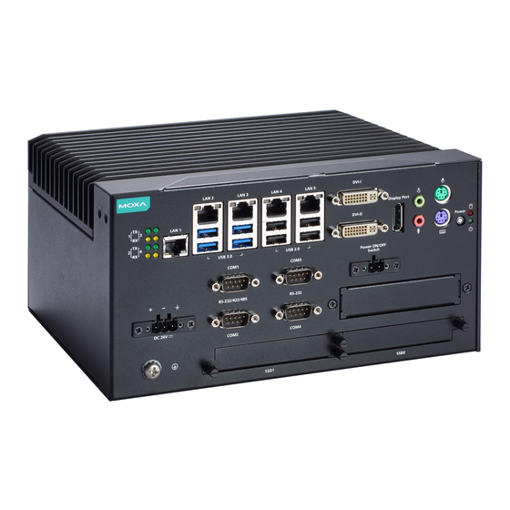
Page 8: Appearance
MC-7400 Series HW UM Hardware Introduction Appearance MC-7410 AC Model MC-7410 DC Model... - Page 9 MC-7400 Series HW UM Hardware Introduction MC-7420 AC Model MC-7420 DC Model...
-
Page 10: Dimensions
MC-7400 Series HW UM Hardware Introduction Dimensions MC-7410 AC Model MC-7410 DC Model MC-7420 AC Model MC-7420 DC Model... -
Page 11: Led Indicators
MC-7400 Series HW UM Hardware Introduction LED Indicators LED Name LED Color LED Function Power Green Power is on and the device is functioning normally Power is off or error powering the device Storage Yellow Blinking: Data transmission No data transmission... -
Page 12: Hardware Connection Description
Hardware Connection Description In this chapter, we show how to connect the embedded computers to the network and to various devices. The following topics are covered in this chapter: Installing the MC-7400 Wall Mounting Wiring Requirements Connecting the Power ... -
Page 13: Installing The Mc-7400
The MC-7400 can be installed on a wall by using the wall-mounting kit that is included in the package. STEP 1: Use eight screws for each bracket and attach the brackets to the rear of the MC-7400. STEP 2: Use two screws (Ø3.7 mm, 60 mm in length) per side to attach the MC-7400 to a wall. -
Page 14: Wiring Requirements
Connecting the Power The MC-7400 Series comes with a 100 to 240 VAC power input for AC power model, or a 24 VDC power input (via the terminal block) for DC power model. If power is supplied properly, the Power LED will light up. -
Page 15: Grounding The Mc-7400
Connect the wire to an appropriately grounded metal surface. Connecting Data Transmission Cables This section describes how to connect the MC-7400 computer to the network and/or serial devices. Connecting to the Network Plug your network cable into the computer’s Ethernet port. The other end of the cable should be plugged into your Ethernet networking device. -
Page 16: Connecting To A Serial Device
MC-7400 Series HW UM Hardware Connection Description Connecting to a Serial Device The serial ports use DB9 connectors. COM1 and COM2 support RS-232. COM3 and COM4 support RS-232, RS-422, or RS-485. The AP from the CD can be used to configure both COM1 and COM2. For detailed instructions, please refer to Appendix C. -
Page 17: Connecting A Ps/2 Keyboard And Mouse
Connecting to the USB Device The MC-7400 comes with two USB 2.0 hosts on the front panel, four USB 2.0 hosts, and two SuperSpeed USB 3.0 hosts on the rear panel. The USB ports support peripherals such as a keyboard or mouse, or storage devices such as a portable HDD or DVD-ROM. -
Page 18: Connecting To Digital Input And Output Channels
Connecting to Digital Input and Output Channels The MC-7400 comes with four digital input and four digital output channels on the front panel. These input/output channels can be connected with the terminal blocks that have been included in the package. -
Page 19: Connecting To A Dvi-I/Dvi-D Monitor
Connecting to a DVI-I/DVI-D Monitor The MC-7400 computer come with one DVI-I and one DVI-D connectors that can connect to DVI monitors. Use the cable to connect one end to the DVI-I connector and the other end to the monitor. See the following table for DVI-I/DVI-D connector pin assignments. -
Page 20: Connecting To A Displayport Monitor
MC-7400 Series HW UM Hardware Connection Description Connecting to a DisplayPort Monitor The MC-7400 computer come with one DisplayPort connector to connect to monitor which support 4K resolution. Pin No. Signal Definition ML_Lane 0 (p) ML_Lane 0 (n) ML_Lane 1 (p) -
Page 21: Installing The Removable Sata Storage Drive
Installing the Removable SATA Storage Drive The MC-7400 computer comes with two removable SATA storage tray that is accessible through the front panel. Either a SATA hard disk or solid state drive may be installed, but only use of an SSD will ensure full anti-vibration compliance. -
Page 22: Bios Setup
BIOS Setup This chapter describes the BIOS settings of the MC-7400 computer. The BIOS is a set of input/output control routines for peripherals. The BIOS is used to initialize basic peripherals and helps boot the operating system before the operating system is loaded. The BIOS setup allows the user to modify the system configurations of these basic input/output peripherals. -
Page 23: Entering The Bios Setup
MC-7400 Series HW UM BIOS Setup Entering the BIOS Setup To enter the BIOS setup utility, press the “F2” key while the system is booting up. The main BIOS Setup screen is displayed. The following four options are available: Continue:... - Page 24 MC-7400 Series HW UM BIOS Setup The following BIOS configuration screen will be shown when you enter SCU option: When you enter SCU, a basic description of each function key is listed at the bottom of the screen. Refer to these descriptions to learn how to use them.
-
Page 25: Main Information
MC-7400 Series HW UM BIOS Setup Main Information The Main page indicates the system information, such as model name, BIOS version, and CPU type. You can view the basic system hardware information on this page. Advanced Settings The Advanced option displays configuration information on Boot, SATA, internal graphics device, SIO, and... -
Page 26: Boot Configuration
MC-7400 Series HW UM BIOS Setup Boot Configuration This feature allows you to configure a default setting for the keys on the number pad of the computer keyboard. Turning the NumLock on allows you to use the number keys to type out numbers and turning it off activates the key's other functions such as using the keypad as an arrow pad. -
Page 27: Internal Graphics Device
MC-7400 Series HW UM BIOS Setup SATA Port 0 to 2 Hot Plug This feature allows you to enable/disable hot plugging capabilities (the ability to remove the drive while the computer is running) for the storage drives installed on the system. -
Page 28: Miscellaneous Configuration
MC-7400 Series HW UM BIOS Setup Miscellaneous Configuration Power ON after Power Failure Allows you to enable/disable the automatic power up of your computer after a system crash. Options: ON (default), OFF, Last State... -
Page 29: Sio Ite8768E
MC-7400 Series HW UM BIOS Setup SIO ITE8768E Serial Port A Allows you to configure the serial port A. Options: Auto (Default) The system chooses the configure for the resource Enable User configures the resource Disable Port is disabled and no configuration is possible Serial Port B Allows you to configure the serial port B. -
Page 30: Hardware Monitor
MC-7400 Series HW UM BIOS Setup Hardware Monitor This feature allows you to view hardware statistics like CPU and system temperature, voltage levels, and other chipset related information. Console Redirection Console Serial Redirect Enables console redirection function. The display will also output to serial port synchronously. -
Page 31: Smart Recovery Info
MC-7400 Series HW UM BIOS Setup Smart Recovery Info This feature allows you to view the smart recovery settings for your computer. Load Smart Recovery Default Allows you to load the default values for the Smart Recovery function. For details on the Smart Recovery feature, refer to the Smart Recover Software User’s Manual. -
Page 32: Power Settings
MC-7400 Series HW UM BIOS Setup Power Settings The Power menu allows you to configure the power settings for your computer. The Advanced CPU Control option is only available on i7 platform. The C-States option is disabled by default. Auto Wake on S5 This feature allows you to configure auto wake up from S5 status. -
Page 33: Wake On Lan
MC-7400 Series HW UM BIOS Setup Wake on LAN This feature is used to configure a wake on the system by a LAN device from a remote host. Options: Enabled (default), Disable. Boot Settings The feature allows you to configure boot settings. -
Page 34: Boot Delay Time
MC-7400 Series HW UM BIOS Setup Boot Delay Time Allows you to configure the delay time value for users to input hot key during POST time. Options: 0 Second (default), 3 Seconds, 5 Seconds, and 10 Seconds Automatic Failover This setting allows you to enable automatic failover to the next boot device if the default device fails to boot. -
Page 35: Exit Settings
MC-7400 Series HW UM BIOS Setup Exit Settings The feature allows users to save configuration changes and exit the BIOS environment. Exit Saving Changes Allows you to exit the BIOS environment and save the values you have just configured. Options: Yes (default), No Save Change Without Exit Allows you to save changes without exiting the BIOS environment. -
Page 36: Upgrading The Bios
MC-7400 Series HW UM BIOS Setup Upgrading the BIOS This section describes how to upgrade the BIOS. IMPORTANT BIOS upgrades, if not done correctly, can permanently damage the computer. We strongly recommend that you contact Moxa’s technical support staff for assistance in order to obtain all necessary tools and the most current advice before attempting to upgrade the BIOS on any Moxa device. - Page 37 MC-7400 Series HW UM BIOS Setup Step 3: Run the upgrade program on the MC-7400 Computer 1. Reboot the computer, press F12 while booting up to enter the Boot Manager 2. Select USB Disk as the first boot source. Press Enter to continue.
- Page 38 MC-7400 Series HW UM BIOS Setup 6. When the upgrade is finished, the computer will automatically reboot. You can check the BIOS version on Main page of the BIOS Setup to confirm the upgrade. ATTENTION DO NOT switch off the power supply during the BIOS upgrade, since doing so may cause the system to crash.
-
Page 39: Regulatory Approval Statement
Regulatory Approval Statement This device complies with part 15 of the FCC Rules. Operation is subject to the following two conditions: (1) This device may not cause harmful interference, and (2) this device must accept any interference received, including interference that may cause undesired operation. -
Page 40: Adjusting The Audio Mixer Function
Adjusting the Audio Mixer Function This chapter describes how to adjust the of the MC-7400’s audio settings for the Mixer function in the Windows XP and Windows XP Embedded operating systems. Since the Mixer function is enabled by default, you need modify the default settings of the Realtek audio device so that sounds picked up from the microphone will not be recorded. - Page 41 MC-7400 Series HW UM Adjusting the Audio Mixer Function 4. Uncheck Stereo Mix and choose Mix Volume to complete the configuration.
Need help?
Do you have a question about the MC-7400 and is the answer not in the manual?
Questions and answers