Moxa Technologies MC-1200 Series User Manual
Hide thumbs
Also See for MC-1200 Series:
- Quick installation manual (8 pages) ,
- Quick installation manual (16 pages)

Related Manuals for Moxa Technologies MC-1200 Series


Summary of Contents for Moxa Technologies MC-1200 Series
- Page 1 MC-1200 Series Hardware User’s Manual Version 1.0, November 2020 www.moxa.com/product © 2020 Moxa Inc., All rights reserved.
- Page 2 MC-1200 Series Hardware User’s Manual The software described in this manual is furnished under a license agreement and may be used only in accordance with the terms of that agreement. Copyright Notice © 2020 Moxa Inc., All rights reserved. Trademarks The MOXA logo is a registered trademark of Moxa Inc.
-
Page 3: Table Of Contents
Table of Contents Introduction ............................1-1 Package Checklist ..........................1-2 Product Features ..........................1-2 Hardware Specifications ........................1-2 Hardware Block Diagram ........................1-2 Hardware Introduction........................2-1 Appearance ............................2-2 Dimensions ............................2-3 LED Indicators ............................ 2-3 Hardware Connection Description ..................... 3-1 Installing the MC-1200 ........................ -
Page 4: Introduction
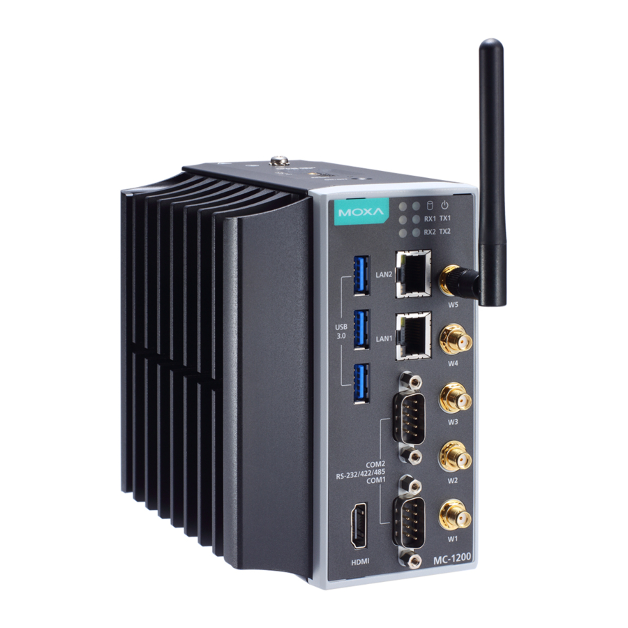
Introduction The MC-1200 Series computers are built around a 7th Gen Intel® Celeron® or Intel® Core™ i3, i5, or i7 processor and come with 1 HDMI display port, 3 USB 3.0 ports, 2 gigabit LAN ports, and 2 3-in-1 RS-232/422/485 serial ports. The MC-1200 is equipped with a 2.5” HDD/SSD slot and a built-in TPM 2.0 module. -
Page 5: Package Checklist
MC-1200 HW UM Introduction Package Checklist • MC-1200 embedded computer • Terminal block to power jack converter • DIN-rail mounting kit • Quick installation guide (printed) • Warranty card NOTE: Please notify your sales representative if any of the above items are missing or damaged. Product Features MC-1200 embedded computers comes with the following: •... -
Page 6: Hardware Introduction
Hardware Introduction The MC-1200 Series embedded computers are compact, well designed, and rugged enough for industrial applications. LED indicators help you monitor the performance and identify trouble spots. Multiple serial ports allow you to connect different devices for wireless operation and the reliable and stable hardware platform lets you devote your attention to developing your applications. -
Page 7: Appearance
MC-1200 HW UM Hardware Introduction Appearance Top View Bottom View Front View... -
Page 8: Dimensions
MC-1200 HW UM Hardware Introduction Dimensions LED Indicators LED Name Status Function Power Green Power is on and computer is functioning normally Power is off Storage 1 (mSATA) Yellow Blinking: Data transmission No data transmission. LAN ½ Green Steady On: 100 Mbps Ethernet link (on connectors) Blinking: Data is being transmitted Yellow... -
Page 9: Hardware Connection Description
Hardware Connection Description In this chapter, we describe how to connect the embedded computer to the network and to various devices. The following topics are covered in this chapter: Installing the MC-1200 Wiring Requirements Connecting the Power ... -
Page 10: Installing The Mc-1200
MC-1200 HW UM Hardware Connection Description Installing the MC-1200 DIN-rail Mounting The MC-1200 comes with a DIN-rail mounting kit for installing the computer on a DIN rail. Installation STEP 1: Use the 4 screws included with the kit to attach the DIN-rail mounting bracket to the MC-1200’s rear panel and tighten the screws to secure the bracket to the MC-1200. - Page 11 MC-1200 HW UM Hardware Connection Description Wall or Cabinet Mounting (DNV) Use the optional wall-mounting kit to install the MC-1200 on to a wall. NOTE The wall-mounting kit can be purchased separately. STEP 1: Use three screws for each bracket and attach the brackets to the rear of the MC-1200.
-
Page 12: Wiring Requirements
MC-1200 HW UM Hardware Connection Description Wiring Requirements In this section, we describe how to connect serial devices to the MC-1200 embedded computer. Be sure to read and follow these common safety precautions before proceeding with the installation of any electronic device: •... -
Page 13: Grounding The Unit
MC-1200 HW UM Hardware Connection Description Grounding the Unit Grounding and wire routing help limit the effects of noise due to electromagnetic interference (EMI). Run the ground connection from the grounding screw (M4) to the grounding surface prior to connecting the power. -
Page 14: Connecting To A Serial Device
MC-1200 HW UM Hardware Connection Description Connecting to a Serial Device Use a serial cable to connect your serial device to the embedded computer’s serial port. The serial ports P1 to P2 have male DB9 connectors and can be configured for RS-232, RS-422, or RS-485 communication. -
Page 15: Connecting To An Hdmi Device
Installing Communications Modules The MC-1200 Series comes with three sockets for installing various communications modules. Unfasten the screws on the right side of the computer and remove the cover to find the locations of these sockets as shown below:... -
Page 16: Installing The Msata Module
MC-1200 HW UM Hardware Connection Description Installing the mSATA Module Insert the mSATA module into the socket and tighter the two screws on the mSATA module to secure it. Installing the Wi-Fi Module The MC-1200 comes with two sockets for users to install up to two Wi-Fi/cellular modules for wireless communication. - Page 17 MC-1200 HW UM Hardware Connection Description Follow these steps to install the Wi-Fi module in the MC-1200. Attach the Wi-Fi module to the mounting plate with two screws.
- Page 18 MC-1200 HW UM Hardware Connection Description Remove the transparent plastic and the blue cover on both sides of the thermal pad and then place it on the top heat sink. Also, remove the blue cover on the heat sink. Place the heat sink with the thermal pad at the center of the wireless module socket.
- Page 19 MC-1200 HW UM Hardware Connection Description Attach one end of the Wi-Fi antenna cable to the connector on the Wi-Fi module and the insert the other end (with the threaded connection ring) through the antenna mounting hole on the front panel of the computer.
-
Page 20: Installing The Cellular Module
MC-1200 HW UM Hardware Connection Description Installing the Cellular Module The MC-1200 comes with two sockets for users to install up to two Wi-Fi/cellular modules for wireless communication. Cellular Module Package The contents of the Wi-Fi module package are shown below: Follow these steps to install the cellular module in the MC-1220. - Page 21 MC-1200 HW UM Hardware Connection Description Place the heat sink with the thermal pad at the center of the cellular module socket. Insert the cellular module in the socket and fasten the two black screws on the module to secure it. There are three connectors on the cellular module: a GPS antenna connector and two cellular antenna connectors.
- Page 22 MC-1200 HW UM Hardware Connection Description Attach one end of the cellular antenna cable to a connector on the cellular module and the insert the other end (with the threaded connection ring) through the antenna mounting hole on the front panel of the computer. Remove the protection cover on the mounting hole before you do so.
- Page 23 MC-1200 HW UM Hardware Connection Description Remove the screws on the bottom panel of the computer and remove the cover. You will see four SIM card slots. Insert a card into the SIM 1 slot. Make sure you insert the card in the right direction as indicated in the image beside the slot.
-
Page 24: Rtc Battery Replacement
MC-1200 HW UM Hardware Connection Description The DIP switch operation is explained below: Status Switch 1 Switch 2 Wi-Fi Wi-Fi OFF (default) Cellular Cellular For example, if you have installed a Wi-Fi module in the first socket, you need to turn the DIP switch 1 to the ON status. RTC Battery Replacement The MC-1200’s real-time clock is powered by a lithium battery. -
Page 25: Bios Setup
BIOS Setup In this chapter, we describe the BIOS settings for the MC-1200 embedded computer. The BIOS is a set of input/output control routines for peripherals to initialize the basic settings. The BIOS firmware helps boot the system before the operating system is loaded. The BIOS setup allows the user to modify the system configuration for basic input/output peripherals. -
Page 26: Entering The Bios Setup
MC-1200 HW UM BIOS Setup Entering the BIOS Setup To enter the BIOS setup utility, press the F2 key while the system is booting up. The main BIOS Setup screen will appear. You can configure the following settings on this screen. Continue: Continue to boot up •... -
Page 27: Main Page
MC-1200 HW UM BIOS Setup The BIOS configuration screen will be shown when you enter the Setup Utility option, as shown in the following figure: Note that the Processor Type information will vary depending on the model that you have purchased. Main Page The Main page displays basic system hardware information, such as model name, BIOS version, and CPU type. -
Page 28: Advanced Settings
MC-1200 HW UM BIOS Setup Advanced Settings Select the Advanced tab in the main menu to open the advanced features screen. - Page 29 MC-1200 HW UM BIOS Setup Boot Configuration This item allows users to configure the default value of Numlock. Options: On (default), Off. SATA Configuration You can use this setting to select the mode for the host drive controller. Options are AHCI (default) and Intel RST Premium.
- Page 30 MC-1200 HW UM BIOS Setup Serial ATA Port This setting displays information on the installed drives. SATA Port Hot Plug This setting allows you to enable/disable hot-plugging capabilities (the ability to remove the drive while the computer is running) that are configured by software for installed storage drives. Options: Disabled (default for Port 0), Enabled (default for Port 1) RAID Set HDC configuration as “Intel RST Premium”...
-
Page 31: Intel Rapid Storage Technology
MC-1200 HW UM BIOS Setup Return to , and select Front Page Device Management When setting the Intel RST Premium mode, or saving changes and reboot, you can select Device Management to configure the following Intel Rapid Storage Technology. Intel Rapid Storage Technology This section allows users to configure Intel®... -
Page 32: Cpu Configuration
MC-1200 HW UM BIOS Setup CPU Configuration NOTE The Hyper Threading function is not supported in the KL1 models. -
Page 33: Video Configuration
MC-1200 HW UM BIOS Setup Active Processor Cores This item indicates the number of cores to enable in each processor package. Hyper-Threading This feature makes the processor resources work more efficiently, enabling multiple threads to run on each core. It also increases processor throughput, improving overall performance on threaded software. Options: Disabled, Enabled (default) Video Configuration DVMT Pre-Allocated... -
Page 34: Chipset Configuration
MC-1200 HW UM BIOS Setup Chipset Configuration This item allows you to configure the chipset settings. Power ON after Power Failure This item allows you to enable/disable the computer from automatically powering up after system power is re-enabled. Options: ON (default), OFF, Last State 4-10... -
Page 35: Sio Ite8786E
MC-1200 HW UM BIOS Setup SIO ITE8786E This section allows users to configure serial port settings. Serial Port A This function allows users to configure the resources for the serial port A. Disable: No resources Enable: User configures the resources Auto (default): EFI/OS chooses the resources Serial Port B This function allows users to configure the resources for the serial port B. -
Page 36: Console Redirection
MC-1200 HW UM BIOS Setup Hardware Monitor This item allows you to view stats such as CPU and system temperature, voltage levels, and other chipset information. Console Redirection When the Console Redirection Function is enabled, the console information will be output to both the HDMI monitor and through the serial port. -
Page 37: Security Settings
MC-1200 HW UM BIOS Setup Security Settings This section allows users to configure security-related settings with a supervisor password and user password. Current TPM Device This item shows if the system has TMP device and its type. TPM State This item allows you view the status of current TPM settings. Clear TPM This item allows users to remove all TPM context associated with a specific owner. -
Page 38: Set Supervisor Password
MC-1200 HW UM BIOS Setup Set Supervisor Password This item allows you to set the supervisor password. Select the Set Supervisor Password option and enter the password and confirm the password again. To delete the password, select the Set Supervisor Password option and enter the old password; leave the new password fields blank, and then press enter. -
Page 39: Power Settings
MC-1200 HW UM BIOS Setup Enable: System will ask input password on post time. Disable: System will ask for the password to go to the setup utility. Config-Only: System will only ask for the password when you select the config (F2) option Power Settings The section allows users to configure power settings. -
Page 40: Mpcie#2 Power
MC-1200 HW UM BIOS Setup mPCIE#2 Power This item allows you to control the power in the 2 mPCIe connector. Options: Off (default), on Boot Settings The section allows users to configure boot settings. NOTE If you do not add any storage, you will not see the EFI option. Boot Type This item allows you to enable/disable the quick boot function. -
Page 41: Usb Boot
MC-1200 HW UM BIOS Setup USB Boot Set booting to USB boot devices capability. Options: Enabled (Default), Disabled Timeout This item allows users to set the number of second that the firmware will wait before booting the original default boot selection. This item allows users to select the boot order. -
Page 42: Exit Discarding Changes
MC-1200 HW UM BIOS Setup Exit Discarding Changes This item allows you to exit without saving any changes that might have been made to the BIOS. Options: Yes (default), No Load Optimal Defaults This item allows you to revert to the factory default BIOS values. Options: Yes (default), No Load Custom Defaults This item allows you to load custom default values for the BIOS settings. -
Page 43: Enabling Amt
MC-1200 HW UM BIOS Setup Enabling AMT NOTE The AMT function is not supported in the KL1 models. To enter the BIOS setup utility, press the “F2” key while the system is booting up. The main BIOS Setup screen will appear. Five options will be available: 1. - Page 44 MC-1200 HW UM BIOS Setup 3. Type the default password: admin 4. Type the new password. It must include both upper-case and lower-case characters, numbers, and special symbols. E.g., Admin’12. 5. Select Intel® AMT Configuration to enable remote access without a local user present for consent, select User Consent, and then select User Opt-in and change the value to None.
- Page 45 MC-1200 HW UM BIOS Setup 6. Set static IP or DHCP by request. 7. Set Activate Network Access to enable remote access capability. 4-21...
-
Page 46: Using Amt
MC-1200 HW UM BIOS Setup Using AMT You can use any AMT tool available to run the remote management function using a web browser. 1. Type the IP address of your computer as configured in the AMT configuration settings with port 16992. The AMT logon screen will appear. -
Page 47: Upgrading The Bios
MC-1200 HW UM BIOS Setup Upgrading the BIOS This section describes how to upgrade the BIOS on your embedded computer. NOTE It is possible to permanently damage the computer when upgrading the BIOS. We strongly recommend that you contact Moxa’s technical support staff for assistance to obtain all the necessary tools and the most current advice before attempting to upgrade the BIOS on any Moxa device. - Page 48 MC-1200 HW UM BIOS Setup 3. Right-click on the USB disk item and select Format. 4. Select FAT32 and click OK to start formatting the disk. Step 2: Prepare the Upgrade File You must use the BIOS upgrade installation file to upgrade the BIOS. Contact Moxa’s technical department for assistance.
- Page 49 MC-1200 HW UM BIOS Setup Step 3: Run the Upgrade Program on Your Computer 1. Reboot the computer with the boot disk and press F2 to go to the Boot Manager. If the BIOS cannot recognize the USB drive as the boot-up device, the USB drive might not have a partition table.
- Page 50 MC-1200 HW UM BIOS Setup When the upgrade is finished, the computer will automatically reboot. You may check BIOS version on the Main page to confirm the upgrade. If the system has more than one boot device, you will see more than one fsx (x represents the number). 5.
-
Page 51: Regulatory Approval Statement
Regulatory Approval Statement This device complies with part 15 of the FCC Rules. Operation is subject to the following two conditions: (1) This device may not cause harmful interference, and (2) this device must accept any interference received, including interference that may cause undesired operation.
Need help?
Do you have a question about the MC-1200 Series and is the answer not in the manual?
Questions and answers