
Related Manuals for Moxa Technologies MC-3201 Series


Summary of Contents for Moxa Technologies MC-3201 Series
- Page 1 MC-3201 Series Quick Installation Guide Version 1.0, July 2022 Technical Support Contact Information www.moxa.com/support 2022 Moxa Inc. All rights reserved. P/N: 1802032010010 *1802032010010*...
-
Page 2: Package Checklist
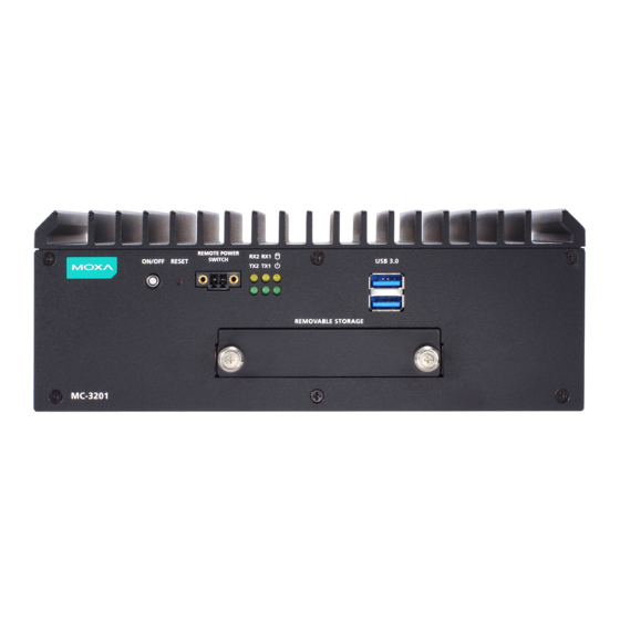
Overview The MC-3201 computers are built around a 11th Gen Intel® Celeron® or Intel® Core™ i3, i5, or i7 processor and come with 2 DisplayPort interfaces, 2 USB 3.0 ports, 4 USB 2.0 ports, 4 GbE ports, and 2 3-in-1 RS-232/422/485 serial ports. - Page 3 Rear Panel MC-3201-TGL1 Front Panel Rear Panel - 3 -...
-
Page 4: Led Indicators
LED Indicators The following table describes the function of the LED indicators located on the front and rear panels: LED Name Status Description Power Power is on and computer is Green functioning normally Power is off Storage 1 (mSATA) Yellow Blinking: Data transmission No data transmission. - Page 5 Installing the MC-3201 Wall Mounting The MC-3201 can be installed on a wall by using the wall-mounting kit. To install the MC-3201 on a wall, do the following: STEP 1: Use four screws for each bracket and attach the brackets to the back of the MC-3201.
-
Page 6: Connector Descriptions
Connector Descriptions Power Connector Connect the power connector/terminal block to the power supply that can provide 9 to 36 VDC (MC- 3201-TGL1 model) or 24 VDC (MC-3201-TGL7 model). Before connecting the device to DC power inputs, make sure the DC power source voltage is stable. - Page 7 NOTE A 4 mm conductor must be used when the connection to the external grounding screw is utilized. The heat sink is grounded to the chassis by an internal screw. Terminal Block Terminal block (J1)—R/C (XCFR2, XCFR8), socket soldered on to the PWB, DINKLE ENTERPRISE CO., LTD, type 5EHDRM, rated 300 V, 15 A, 105°C.
- Page 8 NOTE Make sure you use a DP-certified cable for a reliable audio or video connection. Installing Storage Disk The MC-3201 comes with one slot for installing a storage disk such as a hard disk drive or solid-state drive. NOTE The storage disk should be installed and maintained by a skilled person.
- Page 9 Step 5: Insert the storage tray into the storage slot of the MC-3201. Ensure that you insert the tray into the plastic rails on both sides of the slot. Step 6: Pull the latch on the tray to the right to secure the tray in the slot.
Need help?
Do you have a question about the MC-3201 Series and is the answer not in the manual?
Questions and answers