Moxa Technologies MC-1112 Series Quick Installation Manual
Hide thumbs
Also See for MC-1112 Series:
- Hardware user manual (62 pages) ,
- Quick installation manual (16 pages)
Advertisement
MC-1112/1122 Series
Quick Installation Guide
Moxa Americas:
Toll-free: 1-888-669-2872
Tel:
1-714-528-6777
Fax:
1-714-528-6778
Moxa Europe:
Tel:
+49-89-3 70 03 99-0
Fax:
+49-89-3 70 03 99-99
Moxa India:
Tel:
+91-80-4172-9088
Fax:
+91-80-4132-1045
Edition 1.0, October 2017
Technical Support Contact Information
www.moxa.com/support
2017 Moxa Inc. All rights reserved.
Moxa China (Shanghai office):
Toll-free: 800-820-5036
Tel:
+86-21-5258-9955
Fax:
+86-21-5258-5505
Moxa Asia-Pacific:
Tel:
+886-2-8919-1230
Fax:
+886-2-8919-1231
P/N: 1802011000021
*1802011000021*
Advertisement
Table of Contents

Subscribe to Our Youtube Channel
Related Manuals for Moxa Technologies MC-1112 Series


Summary of Contents for Moxa Technologies MC-1112 Series
- Page 1 MC-1112/1122 Series Quick Installation Guide Edition 1.0, October 2017 Technical Support Contact Information www.moxa.com/support Moxa Americas: Moxa China (Shanghai office): Toll-free: 1-888-669-2872 Toll-free: 800-820-5036 Tel: 1-714-528-6777 Tel: +86-21-5258-9955 Fax: 1-714-528-6778 Fax: +86-21-5258-5505 Moxa Europe: Moxa Asia-Pacific: Tel: +49-89-3 70 03 99-0 Tel: +886-2-8919-1230 Fax:...
-
Page 2: Package Checklist
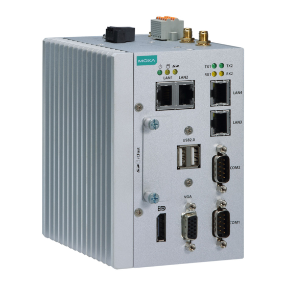
Warranty card Please notify your sales representative if any of the above items are missing or damaged. MC-1112 Panel Layout The following figures show the panel layouts of the MC-1112 Series: Top View Front View Rear View - 2 -... -
Page 3: Mc-1122 Panel Layout
MC-1122 Panel Layout The following figures show the panel layouts of the MC-1122 Series: Top View Front View Rear View LED Indicators The following table describes the LED indicators located on the front panel of the MC-1112/1122: LED Name Status Function Power is on and the computer is Green functioning normally... -
Page 4: Installation
Installing the MC-1112/1122 DIN-Rail Mounting The MC-1112/1122 comes with a DIN-rail mounting kit. To install the DIN-rail mounting kit, do the following: Installation: STEP 1: Use the 4 screws included in the kit to attach the DIN-rail mounting bracket to the MC-1112/1122’s rear panel and tighten the screws to secure the bracket to the MC-1112/1122. -
Page 5: Connector Description
Connector Description Power Connector Use a LPS (12-36 VDC) or Class 2 power cord to connect to the MC-1112/1122's “terminal block to power jack converter” and then turn on the power. If the power is supplied properly, the power LED will light up. - Page 6 Serial Ports The serial ports use DB9 connectors. Each port can be configured by software as a RS-232, RS-422, or RS-485 port. The pin assignments for the ports are shown in the following table: RS-485 RS-485 RS-232 RS-422 (4-wire) (2-wire) TxDA(-) TxDA(-) –...
Need help?
Do you have a question about the MC-1112 Series and is the answer not in the manual?
Questions and answers