Moxa Technologies MC-1100 Series Quick Installation Manual
Hide thumbs
Also See for MC-1100 Series:
- Hardware user manual (62 pages) ,
- Quick installation manual (16 pages)
Table of Contents
Advertisement
Quick Links
Quick Installation Guide
Moxa Americas:
Toll-free: 1-888-669-2872
Tel:
1-714-528-6777
Fax:
1-714-528-6778
Moxa Europe:
Tel:
+49-89-3 70 03 99-0
Fax:
+49-89-3 70 03 99-99
Moxa India:
Tel:
+91-80-4172-9088
Fax:
+91-80-4132-1045
MC-1100 Series
Edition 2.0, November 2017
Technical Support Contact Information
www.moxa.com/support
2017 Moxa Inc. All rights reserved.
Moxa China (Shanghai office):
Toll-free: 800-820-5036
Tel:
+86-21-5258-9955
Fax:
+86-21-5258-5505
Moxa Asia-Pacific:
Tel:
+886-2-8919-1230
Fax:
+886-2-8919-1231
P/N: 1802011000022
*1802011000022*
Advertisement
Table of Contents

Related Manuals for Moxa Technologies MC-1100 Series


Summary of Contents for Moxa Technologies MC-1100 Series
-
Page 1: Quick Installation Guide
MC-1100 Series Quick Installation Guide Edition 2.0, November 2017 Technical Support Contact Information www.moxa.com/support Moxa Americas: Moxa China (Shanghai office): Toll-free: 1-888-669-2872 Toll-free: 800-820-5036 Tel: 1-714-528-6777 Tel: +86-21-5258-9955 Fax: 1-714-528-6778 Fax: +86-21-5258-5505 Moxa Europe: Moxa Asia-Pacific: Tel: +49-89-3 70 03 99-0... -
Page 2: Package Checklist
Oil & Gas field site monitoring, and transportation. The MC-1100 Series comes with hardware monitoring features built in for device I/O status monitoring and alerts, system temperature monitoring and alerts, and system power management. Monitoring system status closely makes it easier to recover from errors and provides the most reliable platform for your applications. -
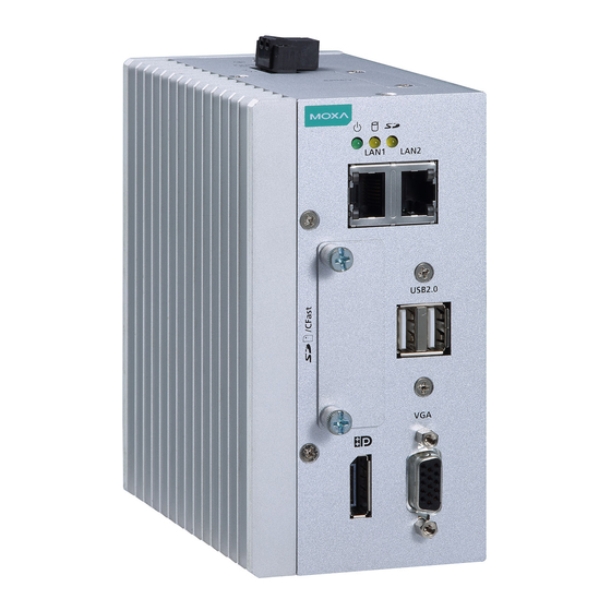
Page 3: Mc-1121 Panel Layout
MC-1121 Panel Layout The following figures show the panel layouts of the MC-1121 Series: Top View Front View Rear View MC-1112 Panel Layout Top View Front View Rear View - 3 -... -
Page 4: Mc-1122 Panel Layout
MC-1122 Panel Layout Top View Front View Rear View LED Indicators The following table describes the LED indicators located on the front panel of the MC-1100: LED Name Status Description Power Power is on and computer is functioning Green normally Power is off Storage 1 (CFast) Yellow Blinking: Data transmission... -
Page 5: Installing A Wireless Module
Installing a Wireless Module Both the MC-1121 and MC-1122 models have been provided with an in-built mini-PCIe socket for installing a wireless module. To install a wireless modules in your MC-1100 computer, do the following: STEP 1: Loosen the six screws on the right panel and the two screws on the bottom panel. - Page 6 STEP 3: Insert the wireless module card at an angle. STEP 4: Push the wireless module card down. STEP 5: Secure the wireless module card with the 2 screws included in the package. STEP 6: Connect the antenna cable connector to the wireless module card.
-
Page 7: Installing The Mc-1100
STEP 7: Replace the side and bottom covers and secure them with screws. STEP 8: (Optional) You can install external 3G, 4G, and Wi-Fi antennas from Moxa to increase the wireless coverage. Contact a Moxa sales representative for details. A MC-1100 computer with external antennas installed is shown here. -
Page 8: Connector Description
STEP 2: Insert the top of the DIN rail into the slot just below the upper hook of the DIN-rail mounting kit. STEP 3: Press the MC-1100 towards the DIN-rail until it snaps into place. Removal: STEP 1: Pull down the latch on the mounting kit with a screwdriver. - Page 9 Grounding the MC-1100 Grounding and wire routing help limit the effects of noise due to electromagnetic interference (EMI). Run the ground connection from the grounding screw (M4) to the grounding surface prior to connecting the power as shown in the illustrations below: MC-1111 MC-1121 MC-1112...
- Page 10 Serial Ports The serial ports use DB9 connectors. Each port can be configured by software for RS-232, RS-422, or RS-485 port. The pin assignments for the ports are shown in the following table: RS-485 RS-485 RS-232 RS-422 (4-wire) (2-wire) TxDA(-) TxDA(-) –...
Need help?
Do you have a question about the MC-1100 Series and is the answer not in the manual?
Questions and answers