
Related Manuals for Moxa Technologies MC-4510-C23


Summary of Contents for Moxa Technologies MC-4510-C23
- Page 1 MC-4510-C23 Hardware User’s Manual www.moxa.com/product Third Edition, October 2010 2010 Moxa Inc. All rights reserved. Reproduction without permission is prohibited.
-
Page 2: Copyright Notice
MC-4510-C23 Hardware User’s Manual The software described in this manual is furnished under a license agreement and may be used only in accordance with the terms of that agreement. Copyright Notice Copyright 2010 Moxa Inc. All rights reserved. Reproduction without permission is prohibited. -
Page 3: Table Of Contents
Table of Contents Chapter 1 Introduction .....................1-1 Overview..........................1-2 Package Checklist ........................1-2 Product Features........................1-2 MC-4510-C23 Hardware Specifications .................. 1-3 Hardware Block Diagram ......................1-5 Chapter 2 Hardware Introduction................2-1 Appearance ..........................2-2 Dimensions ..........................2-2 LED Indicators ......................... 2-3 Real Time Clock ........................ -
Page 4: Chapter 1 Introduction
Introduction Ch a p te r 1 The MC-4510-C23 computer is based on the Intel Core 2 Duo mobile processor and comes with 2 optically isolated RS-232/422/485 serial ports, 2 Gigabit Ethernet ports, 6 USB 2.0 hosts, and a CompactFlash socket, offering high performance and versatile peripherals for marine, railway, power, and other industrial applications. -
Page 5: Overview
Introduction Overview The MC-4510-C23 computer is based on the Intel Core 2 Duo mobile processor and comes with 2 optically isolated RS-232/422/485 serial ports, 2 Gigabit Ethernet ports, 6 USB 2.0 hosts, and a CompactFlash socket, offering high performance and versatile peripherals for marine, railway, power, and other industrial applications. -
Page 6: Mc-4510-C23 Hardware Specifications
MC-4510-C23 HW User’s Manual Introduction MC-4510-C23 Hardware Specifications Computer Intel Core 2 Duo SP9300 2.26 GHz, 6 MB for L2 cache Windows 7, Windows XP SP3, Windows XP Embedded (Must be installed by the user) System Chipset Intel GS45 + ICH9M... - Page 7 MC-4510-C23 HW User’s Manual Introduction Operating 5 to 95% RH Humidity Storage -20 to 60°C (-4 to 140°F) Temperature 0.7 @ DNV 2.4 (Class A), sine wave, 2-100 Hz, 1 Oct./min., 1.5 hr Anti-vibration per axis 1 grms @ DNV 2.4, random wave, 3-100 Hz, 2.5 hr per axis 2.1 g @ DNV 2.4 (Class C), sine wave, 2-50 Hz, 1 Oct./min., 1.5 hr...
-
Page 8: Hardware Block Diagram
MC-4510-C23 HW User’s Manual Introduction Hardware Block Diagram... -
Page 9: Chapter 2 Hardware Introduction
Hardware Introduction Ch a p te r 2 The MC-4510-C23 computer is compact, well-designed, and built rugged enough for industrial applications. LED indicators help you monitor performance and identify trouble spots, multiple serial ports allow you to connect different devices for wireless operation, and the reliable and stable hardware platform lets you devote your attention to developing your applications. -
Page 10: Appearance
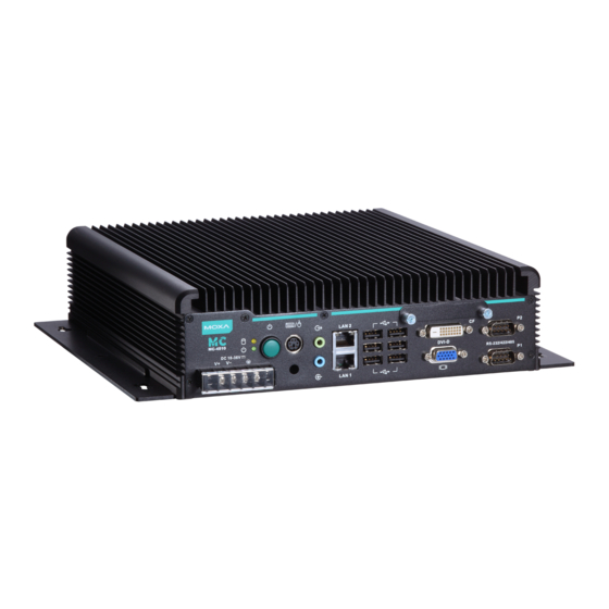
MC-4510-C23 HW User’s Manual Hardware Introduction Appearance MC-4510-C23 Front View Dimensions... -
Page 11: Led Indicators
MC-4510-C23 HW User’s Manual Hardware Introduction LED Indicators LED Name LED Color LED Function Power is on and functioning normally Green Power Power is off or a power error exists CF card is inserted and detected Yellow (on) Yellow CF card or HDD is reading/writing... -
Page 12: Hardware Connection Description
In this chapter, we cover the following topics: Installing the MC4510-C23 Wiring Requirements Connecting the Power Grounding the MC-4510-C23 Connecting Data Transmission Cables Connecting to the Network Connecting to a Serial Device ... -
Page 13: Installing The Mc4510-C23
The MC-4510-C23 has been pre-installed with two brackets on both ends of the computer. Use two screws per side to attach the MC-4510-C23 to a wall or cabinet. Step 1: Use two screws for each bracket and attach the bracket to the rear of the MC-4510-C23. Wiring Requirements This section describes how to connect serial devices to the embedded computer. -
Page 14: Connecting The Power
Connecting the Power The MC-4510-C23 offers 18 to 36 VDC power input with the terminal block. If the power is supplied properly, the Power LED will light up. The OS is ready when the Ready LED glows a solid green. -
Page 15: Connecting Data Transmission Cables
MC-4510-C23 HW User’s Manual Hardware Connection Description Connecting Data Transmission Cables This section describes how to connect the MC-4510-C23 computer to the network and serial devices. Connecting to the Network Plug your network cable into the embedded computer’s Ethernet port. The other end of the cable should be plugged into your Ethernet network. -
Page 16: Connecting To A Serial Device
RxDA(-) DataA(-) Installing a CompactFlash Card The MC-4510-C23 computer comes come with a CompactFlash socket. To insert a CompactFlash card, follow these instructions: 1. Disconnect the MC-4510-C23 from its power source. 2. The CompactFlash socket is located on the right side of the front panel. Unscrew the... - Page 17 4. Gently insert the CompactFlash card into the CF socket, making sure that the card is oriented correctly. ATTENTION The MC-4510-C23 embedded computer does not support the CompactFlash hot swap and PnP (Plug and Play) functions. It is necessary to remove power source first before inserting or removing the CompactFlash card.
-
Page 18: Connecting A Ps/2 Keyboard And Mouse
USB-based keyboard and mouse. ATTENTION Please note that without a Y-type cable, the PS/2 connector on the MC-4510-C23 can only work with a PS/2 keyboard. A PS/2 mouse will not function when directly connected to the PS/2... -
Page 19: Connecting To The Usb Device
Connecting to the USB Device The MC-4510-C23 comes with 6 USB 2.0 hosts on the front panel.. The hosts can be used for an external flash disk or hard drive for storing large amounts of data. You can also use these USB hosts to connect to a keyboard or a mouse. -
Page 20: Connecting To A Dvi-D Monitor
Connecting to a DVI-D Monitor The MC-4510-C23 computers come with a DVI-D connector that can connect to a DVI monitor. Use the cable to connect one end to the DVI-D connector and the other end to the monitor. See the following table for DVI-D connector pin assignments. -
Page 21: Connecting To A Speaker Or A Headphone
MC-4510-C23 HW User’s Manual Hardware Connection Description Connecting to a Speaker or a Headphone The MC-4510-C23 comes with audio input and output interfaces for connecting a microphone and speaker or headphones. See the following figure for details. Upgrading the Memory Module The MC-4510-C23 computer supports two memory sockets that have been installed with 2 GB DDR2 SDRAM modules (1 GB for each socket). - Page 22 MC-4510-C23 HW User’s Manual Hardware Connection Description 4. Remove the back cover of the computer. You will see two HDD brackets inside. The memory module is located below the first HDD bracket. 5. Remove the four screws of the first HDD bracket. See the following figure for the specific location of the screws.
-
Page 23: Installing A Sata Hard Disk
7. When finished, replace the first HDD bracket and the back cover of the computer. Installing a SATA Hard Disk The MC-4510-C23 has two SATA connectors for installing two SATA hard disks. To install the 2.5-inch SATA hard disks, follow these instructions. - Page 24 MC-4510-C23 HW User’s Manual Hardware Connection Description Installing the Hard Disk on the First HDD Bracket Remove the four screws on the first HDD bracket. Remove two black screws on each side of the bracket, and then take off the cover.
- Page 25 MC-4510-C23 HW User’s Manual Hardware Connection Description When finished, place the bracket on the computer, and use four screws to fasten the bracket. Next, find the location of the power connect and the SATA connectors. There is one power connector which can be used by two SATA hard disks, and there are two SATA connectors for connecting two SATA disks.
- Page 26 MC-4510-C23 HW User’s Manual Hardware Connection Description Installing the Hard Disk on the Second HDD Bracket Remove the four screws on the second HDD bracket. Remove two black screws on each side of the bracket, and then take off the cover.
- Page 27 MC-4510-C23 HW User’s Manual Hardware Connection Description When finished, place the bracket on the computer, and use four screws to fasten the bracket. Next, connect the SATA cable to the SATA connector, and the power cable to the power connector.
-
Page 28: Chapter 4 Bios Setup
BIOS Setup Ch a p te r 4 This chapter describes the BIOS settings of the MC-4510-C23 computer. The BIOS is a set of input/output control routines for peripherals. The BIOS is used to initialize basic peripherals and helps boot the operating system before the operating system is loaded. The BIOS setup allows the user to modify the system configurations of these basic input/output peripherals. -
Page 29: Entering The Bios Setup Utility
MC-4510-C23 HW User’s Manual BIOS Setup Entering the BIOS Setup Utility To enter the BIOS setup utility, press the “Del” key while the system is booting up. The main BIOS Setup screen will appear. A basic description of each function key is listed at the bottom of the screen. Refer to these descriptions to learn how to scroll about the screen, how to select by pressing “Enter,”... -
Page 30: Modifying The Bios Main Settings
MC-4510-C23 HW User’s Manual BIOS Setup Modifying the BIOS Main Settings Basic Configuration After entering the BIOS Setup, or choosing the “Main” option, the BIOS main menu will be displayed. Use this menu to check the basic system information such as memory and IDE hard drive. -
Page 31: Advanced Settings
MC-4510-C23 HW User’s Manual BIOS Setup Advanced Settings The “Advanced Features” screen will appear when choosing the “Advanced” item from the main menu. Hard Disk Boot Priority First/Second/Third Boot Device This option allows users to select or change the device boot priority. You may set 3 levels of priority to determine the boot up sequence for different bootable devices, such as a hard drive, CD-ROM, and removable devices. -
Page 32: Advanced Bios Features
MC-4510-C23 HW User’s Manual BIOS Setup Advanced BIOS Features When you select the “Advanced BIOS Features” option under the “Advanced” menu, the following configuration menu will appear. CPU Features C1E Function This item allows you to configure the power-saving mode when the CPU is in C1 status. -
Page 33: Advanced Chipset Settings
MC-4510-C23 HW User’s Manual BIOS Setup Quick Power On Self Test This setting allows the system to skip certain tests while the system boots up. Enable this feature to speed up the boot up process. Options: Enabled (default), Disabled Summary Screen Show The summary screen displays system information, including CPU, memory, disk drive, and PCI devices. -
Page 34: Peripherals
MC-4510-C23 HW User’s Manual BIOS Setup Options: Enable (default), Disable Total GFX Memory Sets the maximum amount of system memory that can be allocated as graphics memory. Options: 128 MB, 256 MB (default), MAX. Boot Display This item allows you to choose which display interface will be shown when system is booting up. -
Page 35: Onchip Ide Device
MC-4510-C23 HW User’s Manual BIOS Setup OnChip IDE Device SATA Mode This item allows you to select the IDE mode or AHCI mode for your SATA hard disk.. Options: IDE (default), AHCI Legacy Mode Support This item allows you to enable or disable the legacy USB device. -
Page 36: Super I/O Device
MC-4510-C23 HW User’s Manual BIOS Setup Onboard LAN Boot ROM Decide whether to invoke the boot ROM of the onboard LAN chip. Options: Enabled, Disabled (default) Super I/O Device Debug Port This function allows you to enable/disable the debug port communication. This port is only for engineers who are debugging program. -
Page 37: Power
MC-4510-C23 HW User’s Manual BIOS Setup Power The Power Setup Menu allows you to configure your system power-up/ power-down options. HPET Support This item allows you to enable/disable the HPET (High Precision Event Timer) function. Option: Enabled (default), Disabled HPET Mode This item allows you to select the HPET mode. -
Page 38: Hardware Monitor
MC-4510-C23 HW User’s Manual BIOS Setup Hardware Monitor This item helps monitor the status of the system, including CPU temperature and the voltage of the CPU, SDRAM and battery. CPU Warning Temperature This item allows you to configure what temperature will trigger a high temperature warning. -
Page 39: Exiting The Bios Setup
MC-4510-C23 HW User’s Manual BIOS Setup Load System Default Settings Use this option to load system factory default settings instead of the current BIOS settings. This option is useful for when the system is unstable. Users do not need to remember what settings were active before the system fails. -
Page 40: Upgrading The Bios
MC-4510-C23 HW User’s Manual BIOS Setup Upgrading the BIOS This section describes how to upgrade the BIOS. However, please note that upgrading the BIOS involves high risk of damage to your computer. We strongly recommend that you contact Moxa’s TS staff for assistance and obtain all necessary tools and files before attempting to upgrade. - Page 41 MC-4510-C23 HW User’s Manual BIOS Setup ATTENTION We suggest you use a USB drive with under 2 GB in disk space, as larger USB drives may not support FAT file format and consequently fail to boot. Step 2: Prepare the Upgrade Tool and BIOS Binary File.
- Page 42 MC-4510-C23 HW User’s Manual BIOS Setup 6. Make sure the first boot device is Hard Disk. If it isn’t, press Enter to change it. 7. Select Exit Save & Exit Setup and then press Enter. 8. Choose Y to save to the CMOS and then exit.
- Page 43 MC-4510-C23 HW User’s Manual BIOS Setup 5. Please note that once the BIOS is successfully upgraded, the default BIOS values will be automatically loaded. However, if you wish to re-configure the BIOS settings, press DEL while booting. ATTENTION Do NOT switch off the power supply during the BIOS upgrade, since doing so may cause the system to crash.
-
Page 44: Appendix A Regulatory Approval Statement
Regulatory Approval Statement Ap p e n d i x A This device complies with part 15 of the FCC Rules. Operation is subject to the following two conditions: (1) This device may not cause harmful interference, and (2) this device must accept any interference received, including interference that may cause undesired operation.
Need help?
Do you have a question about the MC-4510-C23 and is the answer not in the manual?
Questions and answers