
Subscribe to Our Youtube Channel
Related Manuals for Moxa Technologies MC-7270-MP-T


Summary of Contents for Moxa Technologies MC-7270-MP-T
- Page 1 MC-7270-MP-T User’s Manual First Edition, September 2014 www.moxa.com/product © 2014 Moxa Inc. All rights reserved.
-
Page 2: Copyright Notice
MC-7270-MP-T User’s Manual The software described in this manual is furnished under a license agreement and may be used only in accordance with the terms of that agreement. Copyright Notice © 2014 Moxa Inc., All rights reserved. Trademarks The MOXA logo is a registered trademark of Moxa Inc. -
Page 3: Table Of Contents
Dimensions ............................2-3 LED Indicators ............................ 2-4 Real Time Clock ..........................2-4 Hardware Connection Description ..................... 3-1 Installing the MC-7270-MP-T ........................ 3-2 Wall or Cabinet Mounting ......................3-2 Wiring Requirements ........................... 3-2 Connecting the Power ......................... 3-3 Grounding the MC-7270-MP-T ......................3-3 Connecting Data Transmission Cables .................... - Page 4 How to Install the Application ....................... C-1 How to Use the “mxSerialInterface” Utility ..................... C-3...
-
Page 5: Introduction
Introduction The chapter describes the product overview, package checklist, product features, and hardware specifications of the MC-7270-MP-T marine computer. The following topics are covered in this chapter: Overview Package Checklist Product Features Hardware Specifications Hardware Block Diagram... -
Page 6: Overview
The Moxa MC-7270-MP-T marine computer is powered by the third generation Intel® Core™ i CPU processor and offers a wide temperature design for use in critical environments. The MC-7270-MP-T provides a full range of I/O connectivity that includes eight NMEA 0183 ports, four serial ports, four Gigabit Ethernet ports, as well as six USB 2.0 and two SuperSpeed USB 3.0 ports. -
Page 7: Hardware Specifications
MC-7270-MP-T Series Introduction Hardware Specifications Computer CPU: Intel® Core™ i7-3555LE, dual core 64-bit 2.5 GHz processor OS: Windows 7, Windows XP SP3, Windows XP Embedded (must be installed by the user) System Chipset: Intel® QM77 Express Chipset System Memory: 16 GB capacity, with 4 GB pre-installed (2 slots total, with a 4 GB DDR3/DDR3L-1600 204... -
Page 8: Physical Characteristics
MC-7270-MP-T Series Introduction Output Channels: 8 output channels Contact Rating: 2 A, 30 VDC / 0.5 A, 125 VAC under resistor load Initial Insulation Resistance: 1000 Mohm (min.) @ 500 VDC Mechanical Endurance: 100,000,000 operations @ 2 A, 30 VDC resistive load Electrical Endurance: 100,000 operations Contact Resistance: Max. -
Page 9: Hardware Block Diagram
MC-7270-MP-T Series Introduction Hardware Block Diagram... -
Page 10: Hardware Introduction
Hardware Introduction The MC-7270-MP-T computer is compact, well-designed, and built rugged enough for industrial applications. LED indicators help you monitor performance and identify trouble spots, multiple serial ports allow you to connect different devices, and the reliable and stable hardware platform lets you devote your attention to developing your applications. -
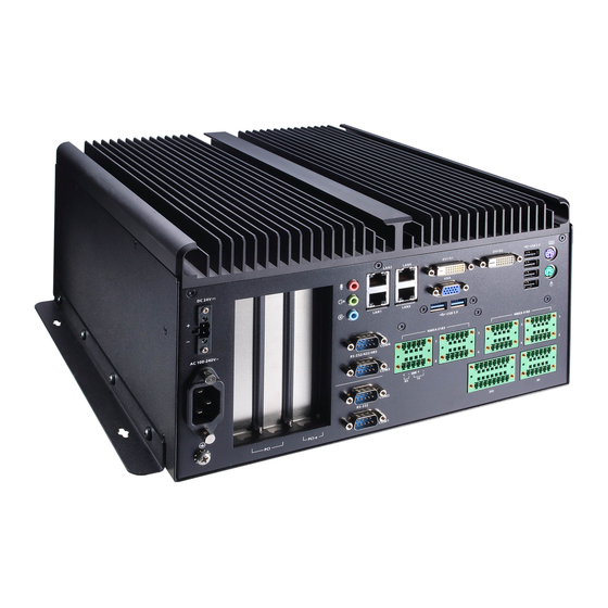
Page 11: Appearance
MC-7270-MP-T Series Hardware Introduction Appearance Front View Rear View... -
Page 12: Dimensions
MC-7270-MP-T Series Hardware Introduction Dimensions... -
Page 13: Led Indicators
MC-7270-MP-T Series Hardware Introduction LED Indicators LED Name LED Color LED Function Power Green Power is on and functioning normally (on front panel) Power is off or power error exists Storage Red (on) Storage disk is functioning properly (on front panel) -
Page 14: Hardware Connection Description
Hardware Connection Description In this chapter, we show how to connect the embedded computers to the network and to various devices. The following topics are covered in this chapter: Installing the MC-7270-MP-T Wall or Cabinet Mounting Wiring Requirements ... -
Page 15: Installing The Mc-7270-Mp-T
Installing the MC-7270-MP-T Wall or Cabinet Mounting The MC-7270-MP-T has brackets for both wall and cabinet mounts. Attach one bracket on each side of the MC-7270-MP-T, and then use suitable screws to attach the brackets to a wall or cabinet. -
Page 16: Connecting The Power
Hardware Connection Description Connecting the Power The MC-7270-MP-T comes with a 100 to 240 VAC power input, and also has a 24 VDC power input (via the terminal block). If power is supplied properly, the Power LED will light up. -
Page 17: Connecting To A Serial Device
MC-7270-MP-T Series Hardware Connection Description 10/100 Mbps 1000 Mbps ETx+ TRD(0)+ ETx- TRD(0)- ERx+ TRD(1)+ TRD(2)+ TRD(2)- ERx- TRD(1)- TRD(3)+ TRD(3)- Connecting to a Serial Device The serial ports use DB9 connectors. COM1 and COM2 support RS-232. COM3 and COM4 support RS-232, RS-422, or RS-485. -
Page 18: Connecting A Ps/2 Keyboard And Mouse
Hardware Connection Description Connecting a PS/2 Keyboard and Mouse Your MC-7270-MP-T computer comes with 2 PS/2 mini-DIN connectors on the rear panel to connect to a PS/2 keyboard and PS/2 mouse. This 6-pin mini-DIN connector has the pin assignments shown below. -
Page 19: Connecting To The Usb Device
Connecting to the USB Device The MC-7270-MP-T comes with two USB 2.0 hosts on the front panel, four USB 2.0 hosts, and two SuperSpeed USB 3.0 hosts on the rear panel. The USB ports support peripherals such as a keyboard or mouse, or storage devices such as a portable HDD or DVD-ROM. -
Page 20: Connecting To Digital Input And Output Channels
Connecting to Digital Input and Output Channels The MC-7270-MP-T comes with eight digital input and eight digital output channels on the rear panel. These input/output channels can be connected with the terminal blocks that have been included in the package. -
Page 21: Connecting To A Vga Monitor
Connecting to a VGA Monitor The MC-7270-MP-T comes with a D-Sub 15-pin female connector on the rear panel to connect a VGA CRT monitor. To ensure that the monitor image remains clear, be sure to fasten the monitor cable using the cable’s thumbscrews after connecting it to the MC-7270-MP-T. -
Page 22: Installing The Removable Sata Storage Drive
Installing the Removable SATA Storage Drive The MC-7270-MP-T computer comes with a removable SATA storage device tray that is accessible through the front panel. Either a SATA hard disk or solid state drive may be installed, but only use of an SSD will ensure full anti-vibration compliance. -
Page 23: Installing Pci And Pcie Cards
Installing PCI and PCIe Cards The MC-7270-MP-T has two universal PCI slots for installing various peripheral cards, such as a RADAR card or PROFIBUS card. Also, a PCIe (x16) card is available for connecting an additional VGA graphic card. To install: 1. -
Page 24: Upgrading The Memory Module
Upgrading the Memory Module The MC-7270-MP-T comes with 4 GB of pre-installed DDR3 SDRAM, which can be extended to 16 GB by adding 8 GB in each of the two slots. If you would like to install more memory modules, please follow the steps below. -
Page 25: Bios Setup
BIOS Setup This chapter describes the BIOS settings of the MC-7270-MP-T computer. The BIOS is a set of input/output control routines for peripherals. The BIOS is used to initialize basic peripherals and helps boot the operating system before the operating system is loaded. The BIOS setup allows the user to modify the system configurations of these basic input/output peripherals. -
Page 26: Entering The Bios Setup Utility
MC-7270-MP-T Series BIOS Setup Entering the BIOS Setup Utility To enter the BIOS setup utility, press the “F2” key while the system is booting up. The main BIOS Setup screen will appear. Select SCU to enter the BIOS configuration. A basic description of each function key is listed at the bottom of the screen. Refer to these descriptions to learn how to use them. -
Page 27: Main Information
MC-7270-MP-T Series BIOS Setup Main Information The main page indicates the system information, such as model name, BIOS version, and CPU type. You may view the basic system hardware information on this page. Advanced Settings The “Advanced Features” screen will appear when choosing the “Advanced” item from the main menu. -
Page 28: Boot Configuration
MC-7270-MP-T Series BIOS Setup Boot Configuration This item allows users to configure the default value of Numlock. Option: On (default), Off. Peripheral Configuration This item allows you to configure the parallel port and audio device. Parallel Port This item allows you to configure the parallel port. -
Page 29: Hdc Configuration
MC-7270-MP-T Series BIOS Setup Mode This setting allows you to configure the mode for the parallel port. Options: SPP (default), EPP, ECP, EPP+ECP HDC Configuration The host drive controller may be configured for IDE (legacy default), AHCI, or RAID mode. When the legacy IDE mode is selected, the following screen will appear. - Page 30 MC-7270-MP-T Series BIOS Setup The Software Feature Mask Configuration will appear as below. RAID 0 is a simple striping of information across two drives. It offers marginal improvements in access times for substantial sacrifices in system reliability. RAID 1 offers full data redundancy across two drives, providing significant improvements in data security and system reliability.
-
Page 31: Video Configuration
MC-7270-MP-T Series BIOS Setup Video Configuration This item allows you to configure the integrated graphics device (IGD) for things like memory allocation (DVMT) and monitor types (Boot Type). Primary Display This item allows you to select the primary display source. -
Page 32: Chipset Configuration
MC-7270-MP-T Series BIOS Setup IGD – Boot Type This item allows you to select the video device that will be activated during POST. Options: VBIOS Default (default), VGA, DVI-D2, DVI-D1 Chipset Configuration This item allows you to configure the chipset settings. -
Page 33: Hardware Monitor
MC-7270-MP-T Series BIOS Setup Hardware Monitor This item allows you to view stats like CPU and system temperature, voltage levels, and other chipset information. Please note that the CPU fan will not start until the temperature is above 80 degrees Celsius. -
Page 34: Set Supervisor Password
MC-7270-MP-T Series BIOS Setup Set Supervisor Password This item allows you set the supervisor password. Select and then enter the password, and then confirm the password again. To delete the password, enter Set Supervisor Password and then enter the old password; then, leave the new password fields blank, and press enter. -
Page 35: Boot Settings
MC-7270-MP-T Series BIOS Setup Boot Settings The section allows users to configure boot settings. Boot Type This item allows you to enable/disable quick boot function. Options: Dual Boot Type (default), Legacy Boot Type, UEFI Boot Type. PXE Boot to LAN This item allows you to enable/disable PXE boot to LAN function. -
Page 36: Efi Device First
MC-7270-MP-T Series BIOS Setup EFI Device First This item allows you to determine EFI device first or legacy device first. If enabled, EFI device will be the first; if disabled, legacy device will be the first. Options: Disabled (default), Enabled Boot Delay Time This item allows you to configure the delay time value for users to input hot key during POST time. -
Page 37: Exit Settings
MC-7270-MP-T Series BIOS Setup Exit Settings The section allows users to exit the BIOS environment. Exit Saving Changes This item allows you to exit the BIOS environment and save the values you have just configured. Options: Yes (default), No Save Change Without Exit This item allows you to save changes without exiting the BIOS environment. -
Page 38: Save Custom Defaults
MC-7270-MP-T Series BIOS Setup Save Custom Defaults This item allows you to save the current BIOS values as a “custom default” that may be reverted to at any time by the “load custom defaults” selection just above. Options: Yes (default), No Discard Changes This item allows you to discard all settings you have just configured. - Page 39 2. Copy the file to the Bootable USB Disk. Step 3: Run the upgrade program on the MC-7270-MP-T Computer 1. Reboot the computer; press F12 while booting up to go to the Boot Manager 2. Select USB Disk as the first boot source, and then press Enter to continue.
-
Page 40: Bios Version
MC-7270-MP-T Series BIOS Setup 6. When the upgrade is complete, the computer will automatically reboot. You may check the BIOS version on the Main page of the BIOS Setup. The following figure shows an example. (Note: The actual BIOS version depends on which version you used.) -
Page 41: Regulatory Approval Statement
Regulatory Approval Statement This device complies with part 15 of the FCC Rules. Operation is subject to the following two conditions: (1) This device may not cause harmful interference, and (2) this device must accept any interference received, including interference that may cause undesired operation. -
Page 42: Adjusting The Audio Mixer Function
Adjusting the Audio Mixer Function This chapter describes how to adjust the of the MC-7270-MP-T’s audio settings for the Mixer function in the Windows XP and Windows XP Embedded operating systems. Since the Mixer function is enabled by default, you need modify the default settings of the Realtek audio device so that sounds picked up from the microphone will not be recorded. - Page 43 MC-7270-MP-T Series Adjusting the Audio Mixer Function 4. Uncheck Stereo Mix and choose Mix Volume to complete the configuration.
-
Page 44: Configuring Serial Ports
Configuring Serial Ports This chapter shows how to configure the 3-mode serial ports, COM3 and COM4, using the application in product CD. The path to the application is <Software DVD>\MC-7270-MP-T\utility\mxsif How to Install the Application 1. Double click the utility Mxsp_MC-7200_1.0_x64_Setup. When the following setup message appears,... - Page 45 MC-7270-MP-T Series Configuring Serial Ports 2. Select Install for anyone using this computer or Install just for me and then click Next > to proceed. 3. Specify which folder on this computer you would like the application to be installed in, and then click...
- Page 46 MC-7270-MP-T Series Configuring Serial Ports 4. Click Finish to complete the installation process. How to Use the “mxSerialInterface” Utility 1. Double click the mxSerialInterface icon. 2. The application UI will appear as shown below. 3. Select COM3 or COM4 from the Port drop-down menu.
- Page 47 MC-7270-MP-T Series Configuring Serial Ports 4. Select “RS232”, “RS485 2 wires”, or “RS422/RS485 4 wires” from the Mode drop-down menu. 5. For example, if you select “COM4” and “RS232” and then click OK, you can use COM4 as an RS-232 serial...
Need help?
Do you have a question about the MC-7270-MP-T and is the answer not in the manual?
Questions and answers