
Subscribe to Our Youtube Channel
Related Manuals for Moxa Technologies MC-3201 Series


Summary of Contents for Moxa Technologies MC-3201 Series
- Page 1 MC-3201 Series Hardware User Manual Version 1.0, July 2022 www.moxa.com/products © 2022 Moxa Inc. All rights reserved.
- Page 2 MC-3201 Series Hardware User Manual The software described in this manual is furnished under a license agreement and may be used only in accordance with the terms of that agreement. Copyright Notice © 2022 Moxa Inc. All rights reserved. Trademarks The MOXA logo is a registered trademark of Moxa Inc.
-
Page 3: Table Of Contents
Table of Contents Introduction ........................... 5 Package Checklist ..........................5 Product Features..........................5 Hardware Specifications ........................5 Hardware Block Diagram ........................6 Hardware Introduction ........................7 Appearance............................. 7 Dimensions ............................ 10 LED Indicators ..........................11 Hardware Connection Description ....................12 Installing the MC-3201........................ - Page 4 Enabling AMT ..........................39 Using AMT ............................. 42 Administering Secure Boot........................ 43 Enabling UEFI Secure Boot ......................44 Enroll EFI Image ........................44 Enroll Customer Key ......................... 45 Upgrading the BIOS ........................47 Regulatory Approval Statement ..................... 51...
-
Page 5: Introduction
Variety of interfaces: 2 serial ports, 4 Giga LAN ports, 2 USB 3.1 (type A) ports, 4 USB 2.0 (type A) ports Built-in TPM 2.0 module • IEC-60945 and E10 compliance • Hardware Specifications NOTE The latest specifications for Moxa’s products can be found at https://moxa.com. MC-3201 Series Hardware User Manual... -
Page 6: Hardware Block Diagram
Hardware Block Diagram MC-3201 Series Hardware User Manual... -
Page 7: Hardware Introduction
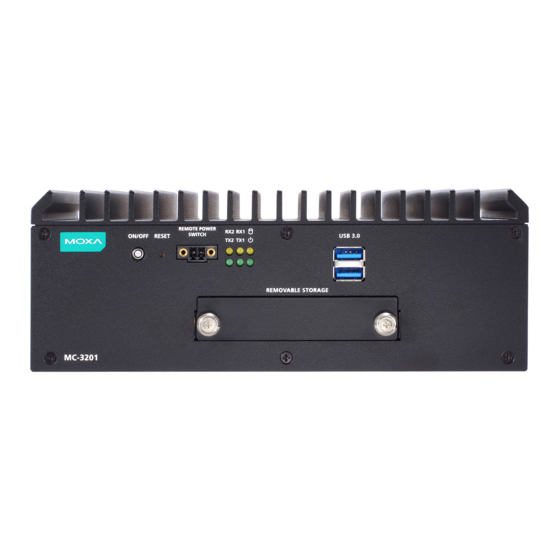
Multiple serial ports allow you to connect different devices. The wireless and LTG modules provide wireless operations, and the reliable and stable hardware platform lets you devote your attention to developing your applications. Appearance MC-3201-TGL1-S-S Front Panel MC-3201 Series Hardware User Manual... - Page 8 MC-3201-TGL1-S-S Rear Panel MC-3201-TGL7-M-S Front Panel MC-3201 Series Hardware User Manual...
- Page 9 MC-3201-TGL7-M-S Rear Panel MC-3201 Series Hardware User Manual...
-
Page 10: Dimensions
Dimensions MC-3201 Series Hardware User Manual... -
Page 11: Led Indicators
Blinking: Data is being transmitted 10 Mbps Ethernet link or LAN is not connected Green Blinking: Data is being transmitted Tx 1/2 (serial ports) No connection Rx 1/2 Yellow Blinking: Data is being transmitted (serial ports) No connection MC-3201 Series Hardware User Manual... -
Page 12: Hardware Connection Description
The screws are included in the wall-mounting kit. If you want to buy the screws separately, use the following specifications: Screw-M/FMS M4x6mm Ni/90D Nylok Step 2: Use two screws per bracket to attach the MC-3201 to a wall or cabinet. MC-3201 Series Hardware User Manual... -
Page 13: Wiring Requirements
Temperature Caution! Be careful when handling the unit. When the unit is plugged in, the internal components generate heat, and consequently the outer casing may feel hot to the touch. MC-3201 Series Hardware User Manual... -
Page 14: Connecting The Power
(M4) to the grounding surface prior to connecting the power. NOTE A 4 mm conductor must be used when the connection to the external grounding screw is utilized. The heat sink is grounded to the chassis by an internal screw. MC-3201 Series Hardware User Manual... -
Page 15: Connecting To A Network
USB ports to connect to a keyboard or a mouse. Connecting to a Display Port The MC-3201 Series offers two display ports located on the rear panel, allowing users to connect to a video device. Make sure you use a certified cable for a reliable video connection. -
Page 16: Connecting To An Audio Input And Output
Connecting to an Audio Input and Output The MC-3201 Series comes with a microphone input and a line output located on the rear panel, allowing users to connect an audio input and an audio output. Connecting to a Digital Input and Digital... -
Page 17: Installing Storage Disk
Unfasten two screws and remove the storage cover on the front panel of the MC-3201. Step 2: Slide the latch on the disk tray to the left and pull out the tray from the slot. MC-3201 Series Hardware User Manual... - Page 18 Put back the cover on the storage slot and fasten the two screws to secure the cover in place. Restricted Access Location This equipment is intended to be used in Restrict Access Location, like control room. The access can only be gained by SERVICE PERSONS or by USERS who have been instructed. MC-3201 Series Hardware User Manual...
-
Page 19: Rtc Battery Replacement
There is a risk of explosion if the battery is replaced by an incorrect type of battery. NOTE The MC-3201 computer can be customized to support an easy RTC battery replacement function. Please contact your Moxa sales representative for details. MC-3201 Series Hardware User Manual... -
Page 20: Bios Setup
Setup Utility: Enter the BIOS configuration menu • Intel® Management Engine BIOS Extension: Enter the AMT configuration menu (not supported in • models with Intel® Celeron® and Core™ i3 processors) Select F2 to enter the BIOS configuration. MC-3201 Series Hardware User Manual... - Page 21 Select or go to Submenu. EN TER The BIOS configuration screen will be shown when you enter the Setup Utility option. NOTE The Processor Type information may vary depending on the model that you have purchased. MC-3201 Series Hardware User Manual...
-
Page 22: Main Page
Main Page The Main page displays basic hardware information, such as model name, BIOS version, and CPU type. Advanced Settings Select the Advanced tab in the main menu to open the advanced features screen. MC-3201 Series Hardware User Manual... -
Page 23: Boot Configuration
Boot Configuration The Numlock option allows configuration of the Numlock value. Options: On (default), Off. SATA Configuration These items allow you to select the SATA speed limit and enable or disable the RAID mode. MC-3201 Series Hardware User Manual... - Page 24 When using the on-request update policy, the master drive data can be restored to a previous state by copying the data on the recovery drive back to the master drive. Source: http://en.wikipedia.org/wiki/Standard_RAID_levels for details. MC-3201 Series Hardware User Manual...
- Page 25 This section allows users to configure Intel® Rapid Storage Technology. After enabling Map SATA Root Port under VMD, saving changes, and rebooting the system, you can select the Device Manager to configure the Intel Rapid Storage Technology settings. MC-3201 Series Hardware User Manual...
-
Page 26: Cpu Configuration
CPU Configuration MC-3201 Series Hardware User Manual... -
Page 27: Video Configuration
2D/3D graphics performance. DVMT Total Gfx Mem. This item allows you to configure the maximum amount of memory DVMT will use when allocating additional memory for the internal graphics device. Options: 256 MB (default), 128 MB, Max. MC-3201 Series Hardware User Manual... -
Page 28: Chipset Configuration
Power ON after Power Failure This item allows you to enable/disable the computer from automatically powering up after system power is re-enabled. Options: ON (default), OFF, Last State PCH-FW Configuration This item allows you to configure the PCH-FW settings. MC-3201 Series Hardware User Manual... -
Page 29: Console Redirection
Console Redirection When the Console Redirection Function is enabled, the console information will be output to both the display monitor and through the serial port. Options: Disabled (default), Enabled MC-3201 Series Hardware User Manual... -
Page 30: Sio Ite8786E
SIO ITE8786E This section allows users to configure SIO settings. MC-3201 Series Hardware User Manual... - Page 31 Disable: Disables the serial port B connection Enable: Enables the Serial Port B connection (default) Hardware Monitor This item allows you to view stats such as CPU and system temperature, voltage levels, and other chipset information. MC-3201 Series Hardware User Manual...
-
Page 32: Security Settings
This item shows if the system has TMP device and its type. TPM State This item allows you view the status of current TPM settings. Clear TPM This item allows users to remove all TPM context associated with a specific owner. MC-3201 Series Hardware User Manual... -
Page 33: Set Supervisor Password
To delete the password, select the Set Supervisor Password option and enter the old password; leave the new password fields blank, and then press enter. After setting the supervisor password, users can choose when the input password screen should be displayed. MC-3201 Series Hardware User Manual... - Page 34 Enable: System will ask for the password on post time Disable: System will ask for the password to go to the setup utility Config-Only: System will only ask for the password when you select the config (F2) option MC-3201 Series Hardware User Manual...
-
Page 35: Power Settings
By Day of Month (user specifies a regular day each month when the computer will power up) M.2 B Key Power This item allows you to control the default power of the M.2 B Key slot. Options: Off (default), on MC-3201 Series Hardware User Manual... -
Page 36: Boot Settings
PXE Booting is booting a system over a network. This item allows users to start PXE over IPv4 or IPv6 Options: Disabled (default), UEFI: IPv4, UEFI: IPv6, UEFI: IPv4/IPv6 USB Boot Set booting to USB boot devices capability. Options: Enabled (Default), Disabled MC-3201 Series Hardware User Manual... -
Page 37: Timeout
This item allows users to set the number of second that the firmware will wait before booting the original default boot selection. This item allows users to select the boot order. Use F5 (move down) or F6 (move up) to change the value. MC-3201 Series Hardware User Manual... -
Page 38: Exit Settings
This item allows you to exit without saving any changes that might have been made to the BIOS. Options: Yes (default), No Load Optimal Defaults This item allows you to revert to the factory default BIOS values. Options: Yes (default), No MC-3201 Series Hardware User Manual... -
Page 39: Load Custom Defaults
To enter the BIOS setup utility, press the “F2” key while the system is booting up. The main BIOS Setup screen will appear. Five options will be available: Select Intel® Management Engine BIOS Extension to enter the AMT configuration. MC-3201 Series Hardware User Manual... - Page 40 Press <Enter> to start the login procedure. Type the default password: admin MC-3201 Series Hardware User Manual...
- Page 41 Select Intel® AMT Configuration to enable remote access without a local user present for consent, select User Consent, and then select User Opt-in and change the value to None. Set static IP or DHCP by request. MC-3201 Series Hardware User Manual...
-
Page 42: Using Amt
You can use any AMT tool available to run the remote management function using a web browser. Type the IP address of your computer as configured in the AMT configuration settings with port 16992. The AMT logon screen will appear. Click Log On and type the username (admin) and password. MC-3201 Series Hardware User Manual... -
Page 43: Administering Secure Boot
Secure Boot helps a computer resist attacks and infection from malware. The feature defines an interface between the operating system and BIOS. It detects tampering with boot loaders, key operation system files, and unauthorized option ROMs by validating their digital signatures. MC-3201 Series Hardware User Manual... -
Page 44: Enabling Uefi Secure Boot
Set as “enabled” in “Restore Secure Boot to Factory Settings” under Administer Secure Boot menu. Press F10 as save and exist. Moxa has put Microsoft key in BIOS in default; if users cannot boot up by “Non Windows OS”, use the following example. Enroll EFI Image MC-3201 Series Hardware User Manual... -
Page 45: Enroll Customer Key
Enter “Administer Secure Boot” once again and see “Select a UEFI file as trusted for execution”, put loader into the database named and followed by the UEFI standard \EFI\BOOT\BOOT{machine type short-name}. E.g., efi\boot\BootX64.efi, Debian (EFI\debian\grubx64.efi), Suse (EFI\opensuse\grubx64.efi) Enroll Customer Key MC-3201 Series Hardware User Manual... - Page 46 Enter “DB OPTION” and enroll your key. Please make sure your key is CRT format and uses RSA 2048 or better. MC-3201 Series Hardware User Manual...
-
Page 47: Upgrading The Bios
Before upgrading the BIOS, you must create a bootable USB drive as a system boot device for use in the future. Insert a USB disk in the computer’s USB drive. Search for “format” and select Create and format hard disk partitions. Right-click on the USB disk item and select Format. MC-3201 Series Hardware User Manual... - Page 48 Reboot the computer with the boot disk and press F2 to go to the Boot Manager. If the BIOS cannot recognize the USB drive as the boot-up device, the USB drive might not have a partition table. Use the Windows command line tool diskpart to rebuild the partition table. MC-3201 Series Hardware User Manual...
- Page 49 Wait until the upgrade procedure is completed. ATTENTION Do NOT switch off the power supply during the BIOS upgrade, since doing so may cause the system to crash. When the upgrade is finished, the computer will automatically reboot. MC-3201 Series Hardware User Manual...
- Page 50 If the system has more than one boot device, you will see more than one fsx (x represents the number). Go to each fsx (x stands for the number) and type ls to view the content of the boot device. If you find an upgrade file, run it. MC-3201 Series Hardware User Manual...
-
Page 51: Regulatory Approval Statement
This is a class A product. If used in a domestic environment, this product may cause undesirable radio interference, in which case the user may be required to take adequate measures to prevent the interference from affecting nearby devices. MC-3201 Series Hardware User Manual...
Need help?
Do you have a question about the MC-3201 Series and is the answer not in the manual?
Questions and answers