Table of Contents
Advertisement
Quick Links
Quick Installation Guide
Moxa Americas:
Toll-free: 1-888-669-2872
Tel:
1-714-528-6777
Fax:
1-714-528-6778
Moxa Europe:
Tel:
+49-89-3 70 03 99-0
Fax:
+49-89-3 70 03 99-99
Moxa India:
Tel:
+91-80-4172-9088
Fax:
+91-80-4132-1045
MC-1200 Series
Version 1.0, June 2020
Technical Support Contact Information
www.moxa.com/support
2020 Moxa Inc. All rights reserved.
Moxa China (Shanghai office):
Toll-free: 800-820-5036
Tel:
+86-21-5258-9955
Fax:
+86-21-5258-5505
Moxa Asia-Pacific:
Tel:
+886-2-8919-1230
Fax:
+886-2-8919-1231
P/N: 1802012004010
*1802012004010*
Advertisement
Table of Contents

Related Manuals for Moxa Technologies MC-1200 Series


Summary of Contents for Moxa Technologies MC-1200 Series
- Page 1 MC-1200 Series Quick Installation Guide Version 1.0, June 2020 Technical Support Contact Information www.moxa.com/support Moxa Americas: Moxa China (Shanghai office): Toll-free: 1-888-669-2872 Toll-free: 800-820-5036 Tel: 1-714-528-6777 Tel: +86-21-5258-9955 Fax: 1-714-528-6778 Fax: +86-21-5258-5505 Moxa Europe: Moxa Asia-Pacific: Tel: +49-89-3 70 03 99-0...
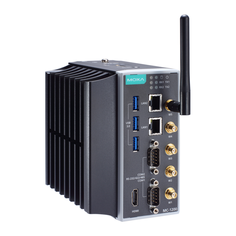
- Page 2 Overview The MC-1200 Series computers are built around a 7th Gen Intel® Celeron® or Intel® Core™ i3, i5, or i7 CPU and come with 1 HDMI display port, 3 USB 3.0 ports, 2 gigabit LAN ports, and 2 3-in-1 RS- 232/422/485 serial ports.
- Page 3 Top View Bottom View LED Indicators The following table describes the function of the LED indicators located on the front panel of the MC-1200: LED Name Status Description Power Power is on and computer is Green functioning normally Power is off Storage 1 (mSATA) Yellow Blinking: Data transmission No data transmission.
- Page 4 Installing the MC-1200 DIN-rail Mounting The MC-1200 comes with a DIN-rail mounting kit. To install the DIN-rail mounting kit, do the following: STEP 1: Use the 4 screws included with the kit to attach the DIN-rail mounting bracket to the MC-1200’s rear panel and tighten the screws to secure the bracket to the MC-1200.
- Page 5 Wall Mounting The MC-1200 can be installed on a wall by using the optional wall- mounting kit. The wall-mounting kit must be purchased separately. STEP 1: Use three screws for each bracket and attach the brackets to the rear of the MC-1200.
- Page 6 Connector Description Power Connector Use an LPS (9-36 VDC) or Class 2 power cord to connect to the MC-1200's terminal block to power jack converter and then turn on the power. If the power is supplied properly, the Power LED will light up.
- Page 7 Ethernet Ports The 10/100/1000 Mbps Ethernet ports use RJ45 connectors. 10/100 Mbps 1000 Mbps ETx+ TRD(0)+ ETx- TRD(0)- ERx+ TRD(1)+ – TRD(2)+ – TRD(2)- ERx- TRD(1)- – TRD(3)+ – TRD(3)- Serial Ports The serial ports use DB9 connectors. Each port can be configured by software as a RS-232, RS-422, or RS-485 port.
Need help?
Do you have a question about the MC-1200 Series and is the answer not in the manual?
Questions and answers