Table of Contents
Advertisement
NT6Q92MA
Nortel
Optical Multiservice Edge
6130
Planning Guide
Standard Rel 1.0 Issue 1 September 2006
What's inside...
Introduction
Feature overview
Configurations and interworking
Hardware description
User interface description
OAM&P description
Technical specifications
Ordering information and system engineering rules
Technical assistance
Appendix A: Data communications planning
*N0082986*
Advertisement
Chapters
Table of Contents

Related Manuals for Nortel Optical Multiservice Edge 6130


Summary of Contents for Nortel Optical Multiservice Edge 6130
- Page 1 NT6Q92MA Nortel Optical Multiservice Edge 6130 Planning Guide Standard Rel 1.0 Issue 1 September 2006 What’s inside... Introduction Feature overview Configurations and interworking Hardware description User interface description OAM&P description Technical specifications Ordering information and system engineering rules Technical assistance...
- Page 2 Nortel Networks, the holder is granted no rights to use the information contained herein. This information is provided “as is”, and Nortel Networks does not make or provide any warranty of any kind, expressed or implied, including any implied warranties of merchantability, non-infringement of third party intellectual property rights, and fitness for a particular purpose.
- Page 3 Publication history September 2006 Standard issue 1 of the document. Planning Guide NT6Q92MA Rel 1.0 Iss 1 Standard September 2006...
- Page 4 Publication history Optical Multiservice Edge 6130 NT6Q92MA Rel 1.0 Iss 1 Standard September 2006...
-
Page 5: Table Of Contents
Security and administration 2-14 Topology Adjacency 2-14 Data communication network 2-15 OME6130 management 2-15 Local Craft Access Terminal 2-15 SNMP traps 2-15 Interworking with Nortel portfolio 2-16 Interoperating with non-Nortel portfolio 2-16 Configurations and interworking 1+1 MSP 3-1 SNCP 3-1 Unprotected configuration 3-2 OME6130 interworking with other products 3-2 Planning Guide NT6Q92MA Rel 1.0 Iss 1 Standard September 2006... - Page 6 Synchronization protection 6-12 Connection management 6-13 Hair-pinning 6-15 Connection management application 6-15 Traffic protection 6-17 Traffic Protection application 6-18 1+1 MSP traffic protection 6-18 Provisioning MSP protected connections 6-18 Optical Multiservice Edge 6130 NT6Q92MA Rel 1.0 Iss 1 Standard September 2006...
- Page 7 Contents vii 1+1 MSP protection switch criteria 6-19 SNCP Traffic Protection 6-20 Provisioning SNCP connections 6-20 SNCP protection switch criteria 6-21 Unprotected connections 6-21 Provisioning unprotected connections 6-22 Data communications 6-22 Interfaces 6-22 DCC Transparency 6-25 OAM comms management 6-26 OAM comms routing 6-26 Alarm and event management 6-27 OME6130 local alarm indications 6-27...
- Page 8 OAM&P Ports 10-3 M1/F1 port 10-3 LAN port (LAN-1-6) 10-3 Network Interface 10-4 STM-1/4 Data Communication Channel 10-7 Data link layer protocols 10-7 STM-1/4 DCC operation mode 10-8 Optical Multiservice Edge 6130 NT6Q92MA Rel 1.0 Iss 1 Standard September 2006...
- Page 9 Contents ix Overhead transparency 10-10 STM-1/4 DCC implementation rules 10-10 IP communication 10-11 Static routing 10-12 Dynamic routing - OSPF 10-12 Dynamic routing - Integrated IS-IS 10-14 Routing protocol configuration 10-15 Proxy ARP 10-15 OSI data communications 10-16 CLNP 10-16 Configure OSI connection 10-17 Configure GRE tunnel 10-18 Configure IP routing 10-21...
- Page 10 IP networks, addressing, and masks 10-93 Dotted decimal notation for IP addresses 10-94 Circuitless IP interface 10-95 ARP 10-96 IP routing protocols 10-97 OSPF 10-97 Route preference 10-102 Static and default routes 10-103 Optical Multiservice Edge 6130 NT6Q92MA Rel 1.0 Iss 1 Standard September 2006...
-
Page 11: About This Document
About this document This planning guide describes the applications and functionality provided by the software and hardware of Nortel Optical Multiservice Edge 6130 (OME6130) Release 1.0. This planning guide covers the following topics: • Introduction • Features overview • Configurations and interworking •... - Page 12 Planning Guide (NT6Q92MA) Local Craft Access User Guide (323-1855-195) References This document refers to the following Optical Multiservice Edge 6130 NTPs: • About the OME6130 NTP Library, 323-1855-090 • Local Craft Access User Guide, 323-1855-195 • Installation, Commissioning and Testing Procedures, 323-1855-201 •...
-
Page 13: Introduction
Introduction The Optical Multiservice Edge 6130 (OME6130) is a compact-MSPP (Multi-Service Provisioning Platform) offering very cost effective transport of Ethernet and TDM services over SDH network. The OME6130 is designed for use in customer sites and in collector networks where multi-service capability is required and compact footprint is paramount. - Page 14 Both 1+1 MSP and SNCP network protection protocols are supported. • Interoperability flexibility: Can be networked either with other OME6130 or OME6110 network elements, or subtended from other Nortel optical products, such as OM4000 or OME6500. • Management flexibility: The OME6130 is fully integrated into Nortel’s Optical Application Platform with OMEA.
-
Page 15: Ome6130 Applications
• Feeder for Metro Optical networks: The OME6130 can be subtended from Nortel’s larger Optical platforms to collect 10/100BT Ethernet, Gigabit Ethernet, E1/DS1, E3/DS3 and STM-1o/e traffic from the Access Edge. Its compact footprint and low price make it well suited for smaller customer locations. -
Page 16: Small Form-Factor Pluggable Interfaces
SR-0, I-1.1/I-4.1, S-1.1/S-4.1, L-1.1/L-4.1, L-1.2/L-4.2, CWDM, STM-1 BX, STM-1e, GE SX and GE LX. Nortel Networks has been collaborating closely with leading SFP vendors to improve the reliability, robustness and manageability of SFPs. The use of such carrier-grade SFP technology enables service providers to enjoy the flexibility of provisioning the interfaces per the requirements of the specific application. -
Page 17: Tdm Switching
Hairpinning is also supported between client ports. Network management The OME6130 is managed as an integral part of Nortel Networks' market proven end-to-end optical portfolio management capabilities. This framework supports a sophisticated and highly customizable desktop providing... -
Page 18: Key Features And Benefits
— dynamically pluggable optical and electrical SFP interfaces (lowers sparing costs) — flexible, complete and easy to use network and service management leading to simplified operations for rolling out and maintaining services Optical Multiservice Edge 6130 NT6Q92MA Rel 1.0 Iss 1 Standard September 2006... -
Page 19: Feature Overview
Feature overview This chapter provides an overview of the Optical Multiservice Edge 6130 (OME6130) Release 1.0 supported features. Release 1.0 supports SDH optical interfaces (STM-1/STM-4), electrical STM-1e interface as well as transport of 10/100 BT (Base-T) Ethernet, Gigabit Ethernet and PDH/DSn services. - Page 20 — low order path alarms — E1/E3/DS1/DS3 alarms — 10/100BT Ethernet and Gigabit Ethernet alarms • performance monitoring: — SDH regenerator section, multiplex section PM parameters — high order path PM parameters Optical Multiservice Edge 6130 NT6Q92MA Rel 1.0 Iss 1 Standard September 2006...
- Page 21 — co-existing on rings: – TN-1C/1X Table 2-1 lists the features available in the Optical Multiservice Edge 6130. For more information about these features, refer to the appropriate reference in this planning guide. The following sections in this chapter give a brief description of the main features.
- Page 22 8-10 STM-1/4 CWDM, STM-1 BX, STM-1e GE SX, LX Configurations 1+1 MSP 1+1 MSP on page 3-1 SNCP SNCP on page 3-1 Unprotected Unprotected configuration on page Optical Multiservice Edge 6130 NT6Q92MA Rel 1.0 Iss 1 Standard September 2006...
- Page 23 Feature overview 2-5 Table 2-1 (continued) Summary of features for current releases Topic OME6130 Reference R1.0 Equipment and facility management Equipment management Equipment management on page 6-3 Facility Management Facility management on page 6-4 Connection management VC11, VC12, VC3 and VC4 cross-connects Connection management on page 6-13 Service Mapping...
- Page 24 Local user account/password management Security and administration on page 6-38 Network element naming, date and time Topology Adjacency Topology adjacency provisioning and discovery Topology adjacency on page 6-41 Data communication network Optical Multiservice Edge 6130 NT6Q92MA Rel 1.0 Iss 1 Standard September 2006...
- Page 25 Web User Interface User interface description on page SNMP v1 and v2 trap monitoring Interworking Nortel portfolio Interworking with Nortel portfolio on page 2-16 non-Nortel portfolio Interoperating with non-Nortel portfolio on page 2-16 Planning Guide NT6Q92MA Rel 1.0 Iss 1 Standard September 2006...
-
Page 26: Physical Description
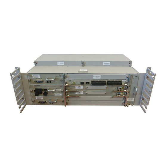
OME6130 chassis layout PSU (2) Aggregate slots (2) Tributary slots (4) For more information, refer to “Hardware description” on page 4-1 “OME6130 network element configuration rules” on page 8-2. Optical Multiservice Edge 6130 NT6Q92MA Rel 1.0 Iss 1 Standard September 2006... -
Page 27: Interface Circuit Packs
Feature overview 2-9 Interface circuit packs The OME6130 Release 1.0 supports one 2x155/622M aggregate circuit pack where two STM-1 or STM-4 line interfaces are present. The OME6130 also supports four tributary slots that can be equipped with the following circuit packs: •... -
Page 28: System Line-Up And Test (Slat)
For more information, refer to SNCP on page 3-1. Unprotected OME6130 supports unprotected configurations. For more information, refer to Unprotected configuration on page 3-2. Optical Multiservice Edge 6130 NT6Q92MA Rel 1.0 Iss 1 Standard September 2006... -
Page 29: Connection Management
Feature overview 2-11 Connection management OME6130 supports nodal port-to-port connection management. OME6130 supports the ability to provision bidirectional and unidirectional connections at VC11, VC12, VC3, and VC4 rates. OME6130 Release 1.0 supports various bandwidth management models that include the following; •... -
Page 30: Traffic Protection
— circuit pack failed on all circuit packs — loss of signal on interface circuit packs — power LED on the OAM circuit pack provides the power status Optical Multiservice Edge 6130 NT6Q92MA Rel 1.0 Iss 1 Standard September 2006... -
Page 31: Performance Monitoring
Feature overview 2-13 • visual alarms interface on the OAM circuit pack provides a summary of active alarms at the shelf level The OME6130 stores active alarms and events which can be viewed from the local craft access terminal. The following alarm reporting control features are supported: profile based path alarm control, alarm filter, and facility alarm reporting. -
Page 32: Loopbacks
Through OMEA management, the topology adjacency feature on the OME6130 provides the capability to manually provision the neighbor status information or to automatically discover it. For more information, refer to Topology adjacency on page 6-41. Optical Multiservice Edge 6130 NT6Q92MA Rel 1.0 Iss 1 Standard September 2006... -
Page 33: Data Communication Network
Feature overview 2-15 Data communication network OME6130 uses an IP-based data communications infrastructure for network element management and for interworking with IP-based network elements. OME6130 also supports IP over OSI via GRE for interworking with OSI-based network elements. iISIS is supported as the internal DCN routing protocol and can be enabled on the DCC interfaces. -
Page 34: Interworking With Nortel Portfolio
2-16 Feature overview Interworking with Nortel portfolio The OME6130 interworks with the following products: • Nortel Optical Manager and Optical Applications Platform • Nortel products through STM-1/4 interfaces OME6130 Release 1.0 will operate with the following network management software: •... -
Page 35: Configurations And Interworking
Configurations and interworking This chapter describes how the Optical Multiservice Edge 6130 (OME6130) Release 1.0 fits in a network and interworks with other Nortel Networks products. Table 3-1 lists the topics in this chapter. Table 3-1 Topics in this chapter... -
Page 36: Unprotected Configuration
For more information about the unprotected protection scheme, refer to Unprotected connections on page 6-21. OME6130 interworking with other products OME6130 is compliant with SDH standards and therefore enables interworking with other SDH compliant network elements. Optical Multiservice Edge 6130 NT6Q92MA Rel 1.0 Iss 1 Standard September 2006... - Page 37 Configurations and interworking 3-3 As shown in Table 3-2, OME6130 Release 1.0 operates with the following network management software. Table 3-2 Network management software that operates with OME6130 Release 1.0 Product Releases Functionality Optical Application Platform 10 / 11 • Fault •...
- Page 38 3-3, OME6130 Release 1.0 interworks with Nortel Networks products through STM-1/4 interfaces or Ethernet/PDH/DSn interfaces. For more information on OME6130 interworking rules and guidelines, refer to the Network Interworking Guide, NTCA68CA. Table 3-3 Nortel Networks products that interwork with OME6130 Release 1.0 Product Release TN-1C TN-1X...
-
Page 39: 4-2 Hardware Description
Hardware description This chapter provides an overview of the Optical Multiservice Edge 6130 (OME6130) hardware. This chapter describes the OME6130 chassis, modules and circuit packs, as listed in Table 4-1. Table 4-1 Topics in this chapter Topic Page Hardware architecture... -
Page 40: Hardware Architecture
4 U 176 mm (6.9 in.) width 445 mm (17.5 in.) depth (shelf only) 231 mm (9.1 in.) depth including cable routing brackets 295 mm (11.6 in.) Optical Multiservice Edge 6130 NT6Q92MA Rel 1.0 Iss 1 Standard September 2006... -
Page 41: Chassis
Hardware description 4-3 Chassis Figure 4-2 provides an overview of the OME6130 chassis layout. Figure 4-2 OME6130 chassis layout PSU (2) OAM Tributary slots (4) Aggregate slots (2) ESD connector Table 4-2 provide the PEC for the OME6130 chassis. Table 4-2 OME6130 chassis Chassis OME6130 System PEC... -
Page 42: Slot Numbers
Ordering information and system engineering rules on page 8-1 the PEC information. Two DC PSUs come equipped with the chassis, but can also be ordered separately for sparing. Optical Multiservice Edge 6130 NT6Q92MA Rel 1.0 Iss 1 Standard September 2006... -
Page 43: Fan Module
Hardware description 4-5 Figure 4-4 OME6130 DC power supply unit PSU (2) Fan module The OME6130 chassis is equipped with a fan module that is located on the right side of the chassis, as shown in Figure 4-2 on page 4-3. -
Page 44: Oam Circuit Pack
(ESI) • alarm output • alarm input • M1/F1 Figure 4-6 shows the OAM circuit pack. Table 4-3 provides a description of the OAM interfaces. Optical Multiservice Edge 6130 NT6Q92MA Rel 1.0 Iss 1 Standard September 2006... - Page 45 Hardware description 4-7 Figure 4-6 OAM circuit pack Table 4-3 OAM port descriptions Port Physical interface Description Craft • RJ-45 connector • 10/100Base-T connectivity between the local craft PC and the OME6130. • RJ-45 connector • Central office LAN provides switched 10/100Base-T connectivity between the carrier’s DCN and the OME6130.
-
Page 46: 2X155/622M Aggregate Circuit Pack
PEC code 2x155/622M aggregate NT6Q45AA Note: The NT6Q45AA PEC cannot be ordered. The NT6Q66AA PEC should be used to order the 2x155/622M aggregate circuit pack with Release 1.0 software. Optical Multiservice Edge 6130 NT6Q92MA Rel 1.0 Iss 1 Standard September 2006... - Page 47 Hardware description 4-9 The PEC for the 2x155/622M aggregate circuit pack with Release 1.0 software is listed in Table 4-5. Table 4-5 2x155/622M aggregate circuit pack with Release 1.0 software 2x155/622M aggregate circuit pack PEC code 2x155/622M aggregate with Release 1.0 NT6Q66AA software Note: The NT6Q66AA PEC should be used to order the 2x155/622M...
-
Page 48: Tributary Interface Circuit Pack Descriptions
OME6130 service modules Interface circuit pack Page 8x10/100BT L1 circuit pack 4-11 2xGE L1 circuit pack 4-13 28xE1/DS1 circuit pack 4-15 3xE3/DS3 circuit pack 4-16 2x155M circuit pack 4-17 Optical Multiservice Edge 6130 NT6Q92MA Rel 1.0 Iss 1 Standard September 2006... -
Page 49: 8X10/100Bt L1 Circuit Pack
Hardware description 4-11 8x10/100BT L1 circuit pack The 8x10/100BT L1 circuit pack can be installed in the tributary slots on the OME6130 chassis to offer 10/100BT Ethernet services. Figure 4-8 shows the faceplate of a 8x10/100BT L1 circuit pack. The PEC for the 8x10/100BT L1 circuit pack is listed in Table 4-7. - Page 50 Refer to Ordering information and system engineering rules on page 8-1 the associated PEC and the sections in OAM&P description on page 6-1 more details on functionality supported. Optical Multiservice Edge 6130 NT6Q92MA Rel 1.0 Iss 1 Standard September 2006...
-
Page 51: 2Xge L1 Circuit Pack
Hardware description 4-13 2xGE L1 circuit pack The 2xGE L1 circuit pack can be installed in the tributary slots on the OME6130 chassis to offer Gigabit Ethernet services. Figure 4-9 shows the faceplate of a 2xGE L1 circuit pack. The 2xGE L1 circuit pack supports pluggable optical transceivers for the two GE interfaces. -
Page 52: Refer To Optical Specifications
Refer to Ordering information and system engineering rules on page 8-1 the associated PEC and the sections in OAM&P description on page 6-1 more details on functionality supported. Optical Multiservice Edge 6130 NT6Q92MA Rel 1.0 Iss 1 Standard September 2006... -
Page 53: 28Xe1/Ds1 Circuit Pack
Hardware description 4-15 28xE1/DS1 circuit pack The 28xE1/DS1 circuit pack can be installed in the tributary slots of the OME6130 chassis. Figure 4-10 shows the faceplate of a 28xE1/DS1 circuit pack. The PEC for the 28xE1/DS1 circuit pack is listed in Table 4-9. -
Page 54: 3Xe3/Ds3 Circuit Pack
E3 or DS3 traffic. A mix of E3 and DS3 services is supported. Refer to the sections in OAM&P description on page 6-1 for more details on functionality supported. Optical Multiservice Edge 6130 NT6Q92MA Rel 1.0 Iss 1 Standard September 2006... -
Page 55: 2X155M Circuit Pack
Hardware description 4-17 2x155M circuit pack The 2x155M circuit pack can be installed in the tributary slots of the OME6130 chassis. Figure 4-12 shows the faceplate of a 2x155M circuit pack. The 2x155M circuit pack supports pluggable optical and electrical transceivers for the two STM-1 line interfaces. -
Page 56: Filler Faceplate
A 64-pin to 64-pin male connector cable must be used to connect to the termination panel. For more information regarding the 75 ohm termination panel and the cable pinout information, refer to E1/DS1 cable pinouts and assemblies on page 7-18 Optical Multiservice Edge 6130 NT6Q92MA Rel 1.0 Iss 1 Standard September 2006... -
Page 57: Cable Routing
Hardware description 4-19 Cable routing The cable routing brackets which are installed at either side of the OME6130 shelf allows for the management of the power cables, OAM cables, optical fibers and the Ethernet/PDH/DSn service cables. The cable routing brackets are placed over the mounting brackets during the installation of the OME6130 shelf. -
Page 58: Ome6130 Shelf Assembly Kit
Release 1.0 System Kit (NT6Q60AA) so they do not need to be ordered separately. Refer to Ordering information and system engineering rules on page 8-1 ordering details of the OME6130 shelf assembly kit. Optical Multiservice Edge 6130 NT6Q92MA Rel 1.0 Iss 1 Standard September 2006... -
Page 59: User Interface Description
User interface description This chapter provides an overview of the craft user interface available for the Optical Multiservice Edge 6130 (OME6130) Release 1.0. Table 5-1 lists the topics in this chapter. Table 5-1 Topics in this chapter Topic Page OME6130 local craft access terminal... -
Page 60: Snmp Traps
For each trap destination, the IP address and the SNMP version (v1 or v2) are provisioned. For more information on how to provision the SNMP trap destinations, refer to Provisioning and Protection Switching Procedures, 323-1855-310. Optical Multiservice Edge 6130 NT6Q92MA Rel 1.0 Iss 1 Standard September 2006... - Page 61 OAM&P description This chapter provides the operations, administration, maintenance and provisioning (OAM&P) description for the Optical Multiservice Edge 6130 network element. Table 6-1 lists the topics in this chapter. Table 6-1 Topics in this chapter Topic Page SDH Configuration System Line-up and Test (SLAT)
-
Page 62: Oam&P Description
6-2 OAM&P description SDH Configuration Optical Multiservice Edge 6130 Release 1.0 is a platform that can be deployed in a SDH environment. System Line-up and Test (SLAT) System Line-up and Test (SLAT) is a two part process consisting of commissioning an OME6130 network element and system testing. -
Page 63: Testing Process
OAM&P description 6-3 Testing process The testing process occurs after the user has completed the powering up and commissioning of the OME6130 network element. The testing process consists of a system level test as follows: • system testing The user performs system testing after all the network elements for a system are physically connected into a linear or ring configuration. -
Page 64: Facility Management
Facility provisioning is a nodal function that allows you to query and edit facility attributes on a specific interface. The user manages facilities from the corresponding application menu in the Provisioning main menu: • • Ethernet • • E1/E3/DS1/DS3 Optical Multiservice Edge 6130 NT6Q92MA Rel 1.0 Iss 1 Standard September 2006... - Page 65 OAM&P description 6-5 By default, the facility is Admin down. When a cross-connect is provisioned with a PDH/DSn facility, its Admin status is automatically changed to Admin Up. When you change a facility from Admin Up to the Admin Down state, the following occurs: •...
-
Page 66: Loopbacks
AIS alarm conditioning. Table 6-2 Loopbacks and AIS alarm conditioning Port type Facility loopback AIS injection on Terminal AIS injection on facility loopback loopback terminal loopback STM-n E1/DS1 Optical Multiservice Edge 6130 NT6Q92MA Rel 1.0 Iss 1 Standard September 2006... -
Page 67: Synchronization Management
OAM&P description 6-7 Table 6-2 Loopbacks and AIS alarm conditioning Port type Facility loopback AIS injection on Terminal AIS injection on facility loopback loopback terminal loopback E3/DS3 10/100BT Ethernet No Gigabit Ethernet The user performs loopbacks on an STM-1/4, 10/100BT Ethernet, Gigabit Ethernet, E1/DS1 and E3/DS3 ports from the Maintenance application in the main menu of the local craft access terminal. - Page 68 The OME6130 can identify a faulty synchronization source and switch to the next highest quality source as defined in the input hierarchy. When all synchronization sources (external or line) are unavailable (caused by faulty Optical Multiservice Edge 6130 NT6Q92MA Rel 1.0 Iss 1 Standard September 2006...
- Page 69 OAM&P description 6-9 sources or lockouts), the OME6130 falls into holdover mode. In the holdover mode, the internal clock operates at a fixed frequency according to the last known frequency reference for a minimum of 24 hours followed by freerun mode (internal stratum 3 [ST3]/G.813 Option 1 compliant 4.6ppm clock).
-
Page 70: Timing Distribution
Optical Multiservice Edge 6130 NT6Q92MA Rel 1.0 Iss 1 Standard September 2006... -
Page 71: Synchronization Status Messages
OAM&P description 6-11 When a timing reference becomes available again, the synchronization hardware automatically transitions to locked mode. The synchronization hardware remains in holdover mode for a minimum of 24 hours. After holdover mode, the synchronization hardware enters the freerun mode. Synchronization status messages Synchronization status messages (SSM) indicate the quality of the timing signals currently available to a network element. -
Page 72: Viewing And Management
• automatic switch • manual switch • forced switch • lockout For more information synchronization protection, refer to Provisioning and Protection Switching Procedures, 323-1855-310. Optical Multiservice Edge 6130 NT6Q92MA Rel 1.0 Iss 1 Standard September 2006... -
Page 73: Connection Management
OAM&P description 6-13 Connection management In the OME6130 architecture, traffic is switched between interface ports on the circuit packs through the cross-connect matrix located on the 2x155/622M aggregate circuit pack. OME6130 supports the following connection management capabilities: • fully non-blocking cross-connects at VC11, VC12, VC3, and VC4 granularity •... - Page 74 — GFP-F to VC12-nv (n=1 to 63) — virtual concatenation at VC12-nv (n=1 to 63) and VC3-nv (n=1 to 3) and VC3-nv (n=1 to 3) for the VCG Optical Multiservice Edge 6130 NT6Q92MA Rel 1.0 Iss 1 Standard September 2006...
-
Page 75: Hair-Pinning
OAM&P description 6-15 Table 6-5 OME6130 service mapping Service Mapping Interconnection type Gigabit • SDH mode: • SDH mode: Ethernet — GFP-F to VC3, and VC4 — non-concatenated at VC3, and VC4 level — GFP-F to VC3-nv (n=1 to 12) and —... - Page 76 AU-4 number 3 • TUG-3 number 2 • TUG-2 number 6 • TU-12/TU-11 payload number 2 For detailed procedures and associated rules, refer to Provisioning and Protection Switching Procedures, 323-1855-310. Optical Multiservice Edge 6130 NT6Q92MA Rel 1.0 Iss 1 Standard September 2006...
-
Page 77: Traffic Protection
OAM&P description 6-17 Traffic protection Traffic protection is a mechanism to enhance the dependability of a transport service. The OME6130 provides a variety of protection mechanisms which can be deployed to tailor the resilience of the platform to that required by the customer. -
Page 78: Traffic Protection Application
The working and protection ports of the 1+1 MSP traffic protection group must be provisioned on the same slot (i.e. slot 6 ports 1 and 2) for the STM-1/4 interfaces of the 2x155/622M aggregate circuit pack. Optical Multiservice Edge 6130 NT6Q92MA Rel 1.0 Iss 1 Standard September 2006... -
Page 79: 1+1 Msp Protection Switch Criteria
OAM&P description 6-19 The working and protection ports of the 1+1 MSP traffic protection groups can be provisioned on the same slot or on different slots for the STM-1 interfaces of the 2x155M tributary circuit packs. Example 1: Working and protection ports on same slot The user can provision a 1+1 MSP traffic protection group with the STM-1 slot 4 port 1 as the working port and the STM-1 slot 4 port 2 as the protection port. -
Page 80: Sncp Traffic Protection
When protection is provisioned for the source or destination end-points of the SNCP connection, the user must also provision the revertive mode and the WTR Time period when applicable. Optical Multiservice Edge 6130 NT6Q92MA Rel 1.0 Iss 1 Standard September 2006... -
Page 81: Sncp Protection Switch Criteria
OAM&P description 6-21 Note: The OME6130 supports nodal provisioning. When provisioning an end-to-end circuit, you must ensure that the traffic protection as well as cross-connections are performed at the end-points as well as any passthrough nodes that make up the end-to-end circuit. For detailed procedures for SNCP protection, refer to Provisioning and Protection Switching Procedures, 323-1855-310. -
Page 82: Provisioning Unprotected Connections
LAN interface consists of a 10/100Base-T RJ-45 port located on the front of the OAM circuit pack. The LAN port can be enabled or disabled with the default being enabled. Optical Multiservice Edge 6130 NT6Q92MA Rel 1.0 Iss 1 Standard September 2006... - Page 83 OAM&P description 6-23 Proxy ARP is supported on the LAN interface when the OME6130 NE is used as a gateway NE. The gateway OME6130 NE responds to ARP requests for the subtending NEs when Proxy ARP is enabled. The subtending NEs need to be added as Proxy ARP neighbours at the gateway OME6130 NE.
- Page 84 DCC interface can be provisioned for each STM-1/4 interface on the OME6130 network element. The generic routing encapsulation (GRE) protocol is used for OSI based DCC interfaces. The GRE tunnels can be provisioned statically or dynamically (auto-GRE tunneling). Optical Multiservice Edge 6130 NT6Q92MA Rel 1.0 Iss 1 Standard September 2006...
-
Page 85: Dcc Transparency
OAM&P description 6-25 Table 6-9 describes the maximum number of RS and MS DCC interfaces supported on the STM-1/4 interfaces for each OME6130 NE. Table 6-9 RS and MS DCC interfaces Maximum number of per OME6130 NE Number of Number of DCC interfaces DCC interfaces None... -
Page 86: Oam Comms Management
Configuration/DCN menu. For more details on how to provision OSPF, refer to Provisioning and Protection Switching Procedures, 323-1855-310. For more information on DCN planning, refer to Appendix A: Data communications planning on page 10-1. Optical Multiservice Edge 6130 NT6Q92MA Rel 1.0 Iss 1 Standard September 2006... -
Page 87: Alarm And Event Management
OAM&P description 6-27 Alarm and event management Active alarms are indicated on the OME6130 equipment and are visible from the local craft access terminal. Alarm history and events are stored on the OME6130 network element. Login sessions using craft user interface, and Optical Application Platform provide details of network element alarms. - Page 88 For more information about the event history and alarm clearing procedures, refer to Local Craft Access User Guide, 323-1855-195 and Trouble Clearing and Module Replacement Procedures, 323-1855-543. Optical Multiservice Edge 6130 NT6Q92MA Rel 1.0 Iss 1 Standard September 2006...
-
Page 89: Alarm Reporting Control
OAM&P description 6-29 Viewing/provisioning alarm severities The Alarm severity application in the Faults menu of the local craft access terminal provides the ability for users to view or edit the severity of an alarm for the OME6130 network element. The severity changes are applied to the alarm type, but is not provisionable on an entity basis. - Page 90 OAM circuit pack. The Environmental alarm input application in the Configuration menu of the local craft access terminal supports the provisioning of alarm for an alarm input point. Optical Multiservice Edge 6130 NT6Q92MA Rel 1.0 Iss 1 Standard September 2006...
-
Page 91: Pdh / Dsn Alarm Monitoring
OAM&P description 6-31 The OME6130 also supports the capability of displaying the network element summary alarms onto an external device. The Critical, Major, and Minor alarms can be reported to an external control device by connecting to the ALM.OUT RJ-45 connector on the front of the OAM circuit pack. For more information on environmental alarms, refer to Local Craft Access User Guide, 323-1855-195 and detailed procedures, refer to Trouble Clearing and Module Replacement Procedures, 323-1855-543. -
Page 92: Performance Monitoring
PM thresholds management for the STM-1/4 interfaces is available from the STM application in the Facility menu of the local craft access terminal. Optical Multiservice Edge 6130 NT6Q92MA Rel 1.0 Iss 1 Standard September 2006... -
Page 93: Stm Pm Parameters
OAM&P description 6-33 STM PM parameters STM PM parameters are accumulated for the STM-1/4 interfaces on the circuit packs. Table 6-11 provides a summary of the supported STM PM parameters. Table 6-11 SDH PM parameters summary Facility PM parameter Regenerator SDH: ES, SES, UAS, SEP, EB, BBE, ESR, SESR, BBER, SEPI Section (RS) Multiplex section... -
Page 94: Pdh / Dsn Pm Parameters
8x10/100BT L1 circuit pack and the Gigabit Ethernet interfaces on the 2xGE L1 circuit pack. Table 6-13 provides a summary of the supported 10/100BT Ethernet and Gigabit Ethernet PM parameters. Optical Multiservice Edge 6130 NT6Q92MA Rel 1.0 Iss 1 Standard September 2006... - Page 95 OAM&P description 6-35 Table 6-13 10/100BT Ethernet and Gigabit Ethernet PM parameters summary Facility PM parameter 10/100BT Ethernet • Alignment Errors • Broadcast Frames Received • Broadcast Frames Transmitted • Collisions • ES • Ethernet Interval Valid • Frame Too Long Errors •...
-
Page 96: Wan Pm Parameters
WAN PM parameters are accumulated for the 10/100BT Ethernet interfaces on the 8x10/100BT L1 circuit pack and the Gigabit Ethernet interfaces on the 2xGE L1 circuit pack. Table 6-14 provides a summary of the supported VCG PM parameters. Optical Multiservice Edge 6130 NT6Q92MA Rel 1.0 Iss 1 Standard September 2006... - Page 97 OAM&P description 6-37 Table 6-14 WAN PM parameters summary Facility PM parameter WAN for 10/100BT • Core Header CRC Errors Ethernet ports • Core Header Single Error Corrections • ES • Frames Dropped • Idle Seconds • Payload FCS Errors •...
-
Page 98: Pm Time Intervals
Local account user authentication uses a user ID and password and is the default method on OME6130 network elements. A user ID and password is managed individually at each network element. Optical Multiservice Edge 6130 NT6Q92MA Rel 1.0 Iss 1 Standard September 2006... -
Page 99: Security Levels
Ethernet/router IP address/masks, OSPF parameters The OME6130 has a default ADMIN level account named ADMIN with ADMIN password. Nortel Networks recommends that the default passwords be changed. See “Local password management” on page 6-40 for more information. -
Page 100: Local Password Management
System Time application on the local craft access terminal. This application provides the following time of day synchronization features: • Date and time setting • Time zone setting Optical Multiservice Edge 6130 NT6Q92MA Rel 1.0 Iss 1 Standard September 2006... -
Page 101: Topology Adjacency
OAM&P description 6-41 • Time server setting Date and time setting The network element date and time can be provisioned using the Set Time application in the System Time menu. Time zone setting The time zone of the OME6130 network element can be provisioned to correspond to the local settings using the Set time zone application in the System Time menu. -
Page 102: Backing Up And Restoring The Network Element Database
HTTP to move configuration between the network element and an external backup repository (laptop or desktop) locally connected to the Craft port. Refer to Installation, Commissioning and Testing Procedures, 323-1855-201, for more information. Optical Multiservice Edge 6130 NT6Q92MA Rel 1.0 Iss 1 Standard September 2006... -
Page 103: Technical Specifications
Technical specifications This chapter provides technical specifications, as listed in Table 7-1, for the Optical Multiservice Edge 6130 (OME6130) network element. Table 7-1 Topics in this chapter Topic Page Physical specifications Power specifications Connector pinouts E1/DS1 cable pinouts and assemblies... -
Page 104: Physical Specifications
231.0 mm / 9.1 in. (shelf only) • OME6130 network element 295.0 mm / 11.6 in. (including configuration rules on page 8-2 cable routing brackets) more information about physical specifications Optical Multiservice Edge 6130 NT6Q92MA Rel 1.0 Iss 1 Standard September 2006... -
Page 105: Power Specifications
Technical specifications 7-3 Figure 7-1 OME6130 chassis - physical specifications PSU (2) OAM Tributary slots (4) Aggregate slots (2) Power specifications The OME6130 equipped with the DC PSU operates from -40 V dc to -57.5 V dc measured at the input terminals of the network element. The following tables list the estimated power consumption for the different modules: •... - Page 106 Table 8-20 on page 8-18 for a list of power cables assemblies available and the Installation, Commissioning and Testing Procedures, 323-1855-201 for details on installing and connecting power to an OME6130 shelf. Optical Multiservice Edge 6130 NT6Q92MA Rel 1.0 Iss 1 Standard September 2006...
-
Page 107: Connector Pinouts
Technical specifications 7-5 Connector pinouts Table 7-7 lists the connectors and the respective tables providing the details of their pin assignments and front views. Table 7-7 Connector pin assignment details Connector Details DC power connector Table 7-8 OAM circuit pack connector pinouts Alarm input connector Table 7-9 Alarm output connector... -
Page 108: Dc Power Connector
2 3 4 5 6 7 8 ALARMIN_4 ALARMIN_3 ALARMIN_2 COMMON Note: The alarm inputs are operating as follows: open circuit = no alarm closed circuit = alarm Optical Multiservice Edge 6130 NT6Q92MA Rel 1.0 Iss 1 Standard September 2006... - Page 109 Technical specifications 7-7 Alarm output connector Table 7-10 Alarm output connector - pin assignment (in NT6Q59AB) Description Usage ALARMOUT_4_RET Unused ALARMOUT_4 ALARMOUT_3_RET Minor ALARMOUT_3 2 3 4 5 6 7 8 ALARMOUT_2_RET Major ALARMOUT_2 ALARMOUT_1_RET Critical ALARMOUT_1 Note 1: Those contacts are normally open. Note 2: For each alarm output, a relay is present between the signal pin and the return pin.
- Page 110 Note: The Ethernet cables connecting to the 10/100BT ports on the 8x10/100BT L1 circuit pack must be shielded twisted pair. Refer to Ethernet service cable assemblies on page 8-14 for ordering information. Optical Multiservice Edge 6130 NT6Q92MA Rel 1.0 Iss 1 Standard September 2006...
-
Page 111: 28Xe1/Ds1 Connector Pinouts
Technical specifications 7-9 28xE1/DS1 connector pinouts Figure 7-2 on page 7-9 shows the faceplate of the 28xE1/DS1 circuit pack. The first 64-pin Telco connector is used for ports 1 to 16 of the circuit pack and the pinout is presented in Table 7-14 for E1 services and Table 7-15... - Page 112 RX10- Brown TX11+ Orange 53 TX11- Orange RX11+ Green RX11- Green TX12+ Blue TX12- Blue RX12+ Brown RX12- Brown TX13+ Orange 57 TX13- Orange RX13+ Green RX13- Green Optical Multiservice Edge 6130 NT6Q92MA Rel 1.0 Iss 1 Standard September 2006...
- Page 113 Technical specifications 7-11 Table 7-14 (continued) E1 connector - pin assignment (NT6Q73BA, NT6Q73CA, NT6Q73DA and NT6Q73EA) TX14+ Blue TX14- Blue RX14+ Brown RX14- Brown TX15+ Orange 61 TX15- Orange RX15+ Green RX15- Green TX16+ Blue TX16- Blue RX16+ Brown RX16- Brown Note: Right routing E1 cables connecting to the 28xE1/DS1 circuit pack must have a shielded connector.
- Page 114 (BK/OR) (BK/OR) TX7(tip) Black TX7(ring) Green (BR/GN) (BK/GN) RX7(tip) 2 Black RX7(ring) Brown (BK/BR) (BK/BR) TX8(tip) Black TX8(ring) Gray (BK/GR) (BK/GR) RX8(tip) 2 Yellow RX8(ring) Blue (YL/BU) (YL/BU) Optical Multiservice Edge 6130 NT6Q92MA Rel 1.0 Iss 1 Standard September 2006...
- Page 115 Technical specifications 7-13 Table 7-15 (continued) DS1 connector - pin assignment (NT6Q73QA and NT6Q73TA) TX9(tip) Yellow TX9(ring) Orange (YL/OR) (YL/OR) RX9(tip) 3 Yellow RX9(ring) Green (YL/GN) (YL/GN) TX10(tip Yellow TX10(ring) 3 Brown (YL/BR) (YL/BR) RX10(tip Yellow RX10(ring) 3 Gray (YL/GR) (YL/GR) TX11(tip Purple...
- Page 116 Green RX25- Green TX26+ Blue TX26- Blue RX26+ Brown RX26- Brown TX27+ Orange 53 TX27- Orange RX27+ Green RX27- Green TX28+ Blue TX28- Blue RX28+ Brown RX28- Brown Optical Multiservice Edge 6130 NT6Q92MA Rel 1.0 Iss 1 Standard September 2006...
- Page 117 Technical specifications 7-15 Table 7-16 (continued) E1 connector (port 17-28) - pin assignment (NT6Q73BA, NT6Q73CA, NT6Q73DA and NT6Q73EA) Note: Right routing E1 cables connecting to the 28xE1/DS1 circuit pack must have a shielded connector. Refer to Table 7-21 on page 7-21 for details on the shielded connector specifications.
- Page 118 TX23(ring) 2 Green (BR/GN) (BK/GN) RX23(tip) 2 Black RX23(ring) 2 Brown (BK/BR) (BK/BR) TX24(tip) 2 Black TX24(ring) 2 Gray (BK/GR) (BK/GR) RX24(tip) 2 Yellow RX24(ring) 2 Blue (YL/BU) (YL/BU) Optical Multiservice Edge 6130 NT6Q92MA Rel 1.0 Iss 1 Standard September 2006...
- Page 119 Technical specifications 7-17 Table 7-17 (continued) DS1 connector (port 17-28) - pin assignment (NT6Q73QA and NT6Q73TA) TX25(tip) 3 Yellow TX25(ring) 3 Orange (YL/OR) (YL/OR) RX25(tip) 3 Yellow RX25(ring) 3 Green (YL/GN) (YL/GN) TX26(tip) 3 Yellow TX26(ring) 3 Brown (YL/BR) (YL/BR) RX26(tip) 3 Yellow RX26(ring) 3...
-
Page 120: E1/Ds1 Cable Pinouts And Assemblies
The following sections detail the pinouts and port mappings for the 120/100 ohm cable assemblies and for the 75 ohm termination panel. The E1/DS1 cables come with right routing. These cable assemblies can be ordered from Nortel (see E1/DS1 cable assemblies on page 8-12) or produced locally to the specifications provided: •... - Page 121 Technical specifications 7-19 Figure 7-3 75 ohm termination panel - 16 channel Note: The 75 ohm termination panel is labeled from 1-16 by default, but includes an additional overlay label which can be installed by the user when connecting the ports 17-28 of the 28xE1/DS1 circuit pack. Table 7-18 Physical specifications for 75 ohm BNC termination panel Feature...
- Page 122 65% Nominal Near End Cross Talk 53 dB at 20 MHz (NEXT) pair to pair Dielectric Strength Conductor to Conductor 2.5 KV DC Core to Sheath 2.3 KV DC Optical Multiservice Edge 6130 NT6Q92MA Rel 1.0 Iss 1 Standard September 2006...
- Page 123 Technical specifications 7-21 Table 7-20 Cable specifications for connecting DS1 ports Feature Physical specification Conductor 24 AWG solid tin plated copper Insulation Solid polyolefin or solid Polyethylene Pairs Two conductors twisted into pairs with varying lay length Pair groups 32 twisted pairs are cabled together Jacket 32 pair groups are jacketed with PVC Colour Code...
- Page 124 Y’d arrangement, or two drain wires) and interference contact to exposed braid at the exit of the cable from hood. Figure 7-4 E1 coaxial cable bundle specification Optical Multiservice Edge 6130 NT6Q92MA Rel 1.0 Iss 1 Standard September 2006...
-
Page 125: Optical Specifications
Technical specifications 7-23 Figure 7-5 64-pin E1/DS1 100 degree right routing cable connector Optical specifications The following sections provide details of the optical specifications. All the optical SFPs for the OME6130 are equipped with LC type connectors. The following assumptions were made when calculating the dispersion and attenuation limited distances quoted in the optical specifications: •... -
Page 126: Stm-1/4 And Ge Sfp Optical Specifications
+/- 2 dB (see Note Optical path Attenuation range 0 dB 0 dB to 12 dB 10 dB to 28 dB 10 dB to to 10 dB 28 dB Optical Multiservice Edge 6130 NT6Q92MA Rel 1.0 Iss 1 Standard September 2006... - Page 127 Technical specifications 7-25 Classification IR1/S1.1 LR1/L1.1 LR2/L1.2 Nominal reach (see Note 2 km 15 km 40 km 80 km Maximum dispersion 96 ps/nm Minimum optical return loss 20 dB Dispersion limited distance 16 km (see Note Attenuation limited distance 2 km 34.3 km 80 km 112 km...
- Page 128 The actual limiting distance is the lower of the dispersion limited or attenuation limited distances. Optical Multiservice Edge 6130 NT6Q92MA Rel 1.0 Iss 1 Standard September 2006...
- Page 129 Technical specifications 7-27 Table 7-25 lists the optical specifications for the STM-1/4 optical SFP. Table 7-25 Optical specifications for STM-1/4 SFPs Classification IR1/S1.1_S4.1 NTTP04CF Transmitter Transmitter type FP laser Nominal wavelength 1310 nm Transmit output power (max) -8 dBm Transmit output power (min) -15 dBm Spectral width 2.5 nm (RMS)
- Page 130 Spectral width 1 nm (-20 dB) Minimum side mode suppression ratio 30 dB Minimum extinction ratio 8.2 dB Power monitor accuracy (see Note +/- 2 dB Receiver Receiver type Optical Multiservice Edge 6130 NT6Q92MA Rel 1.0 Iss 1 Standard September 2006...
- Page 131 Technical specifications 7-29 Table 7-26 (continued) Optical specifications for STM-1/4/16 SFPs Classification 2.5G NRZ CWDM (S-C8L1-1Dx) Wavelength range 1260 nm to 1620 nm Nominal wavelength 1471 nm to 1611 nm @ 20 nm Receiver sensitivity -28 dBm Receiver overload -9 dBm Path penalty 2.5 dB Maximum receive reflectance...
- Page 132 SFP fitted at the other end of the link. The upstream SFP transmits at 1310 nm and receives at 1530 nm, the downstream SFP transmits at 1530 nm and receives at 1310 nm. Optical Multiservice Edge 6130 NT6Q92MA Rel 1.0 Iss 1 Standard September 2006...
- Page 133 Technical specifications 7-31 Table 7-28 lists the optical specifications for the GE optical SFPs. Table 7-28 Optical specifications for GE SFPs Classification SX (see Note NTTP01AF NTTP01CF Transmitter Transmitter type VCSEL FP laser Nominal Wavelength 850 nm 1310 nm Transmit output power (max) <0 dBm (see Note -3 dBm...
- Page 134 The actual limiting distance is the lower of the dispersion limited or attenuation limited distances. Optical Multiservice Edge 6130 NT6Q92MA Rel 1.0 Iss 1 Standard September 2006...
-
Page 135: Electrical Specifications
Technical specifications 7-33 Electrical specifications Table 7-29 Table 7-33 lists the electrical specifications for the E1, E3, DS3, DS1, and STM-1e interfaces. Table 7-29 E1 electrical specifications Parameter Value Line rate 2048 kbit/s +/- 50 ppm Line code HDB3 Framing application CRC4 Impedance 75 ohm or 120 ohm (see Note) - Page 136 Minimum output return loss 15 dB (8 MHz to 240 MHz) Cable loss to input 0 dB to 12.7 dB at 78 MHz Minimum input return loss 15 dB (8 MHz to 240 MHz) Optical Multiservice Edge 6130 NT6Q92MA Rel 1.0 Iss 1 Standard September 2006...
-
Page 137: Environmental Specifications
Technical specifications 7-35 Environmental specifications The following section outlines the environmental specifications including: • operating environment specifications • storage and transportation specifications Operating environment specifications Table 7-34 outlines the OME6130 operating environment specifications. Table 7-34 Operating environmental specifications for OME6130 system Attribute Condition Test method and specification... -
Page 138: Electromagnetic Specifications
8 kV • Telcordia GR-78-CORE • EN 55024:1998+A1:2001+A2:2003 Operational Condition: no effect occurs when the system is exposed to the RF levels described in the specifications above. Optical Multiservice Edge 6130 NT6Q92MA Rel 1.0 Iss 1 Standard September 2006... -
Page 139: Safety Specifications
Technical specifications 7-37 Table 7-35 (continued) Electromagnetic specifications for OME6130 Electromagnetic topic Attribute Test method and specification Electrical fast transient (EFT) power and signal cables • EN 300 386 V1.3.3 4 kV - ground • Telcordia GR-1089-CORE, Iss.3 1 kV - power •... -
Page 140: Power And Grounding Specifications
• NFPA70, (US National Electrical Code) • CSA 22.1, (Canadian Electrical Code) • Telecordia: GR-1089-CORE, Electromagnetic Compatibility and Electrical Safety, Issue 2, Revision 1, February 1999, Section 9 Optical Multiservice Edge 6130 NT6Q92MA Rel 1.0 Iss 1 Standard September 2006... - Page 141 Technical specifications 7-39 Table 7-36 (continued) Power, grounding, and noise references Topic References Noise • ANSI T1.315-2001, Voltage Levels for DC Powered Equipment Used in the Telecommunications Environment, November 2001 • DS8171, Issue 2, 600 Hz and -48 V dc Power for DC Powered Telecommunication Equipment, Bell Canada •...
- Page 142 7-40 Technical specifications Optical Multiservice Edge 6130 NT6Q92MA Rel 1.0 Iss 1 Standard September 2006...
-
Page 143: Ordering Information And System Engineering Rules
Ordering information and system engineering rules This chapter provides the ordering information and engineering rules for the Optical Multiservice Edge 6130 (OME6130) network element. Table 8-1 lists the topics in this chapter. Table 8-1 Topics in this chapter Topic Page... -
Page 144: Ome6130 Network Element Configuration Rules
3xE3/DS3 circuit pack Slots 4, 5, 8, 9 2x155M circuit pack Slots 4, 5, 8, 9 2, 3, Power supply unit Slots 1, 3 (DC) OAM circuit pack Slot 2 Optical Multiservice Edge 6130 NT6Q92MA Rel 1.0 Iss 1 Standard September 2006... - Page 145 Ordering information and system engineering rules 8-3 Table 8-2 (continued) Chassis components Circuit pack or component Slot number Note Fan module Slot 10 SFP interfaces Slots 4, 5, 6, 8, 9 Note 1: The 2x155/622M aggregate circuit pack is only supported in slot 6 in Release 1.0.
-
Page 146: Bay Equipping Rules
5 No fiber slack storage is provided for fibers terminating on the OME6130 shelf. Cable relief off the shelf can be handled using the routing brackets provided with the OME6130 Assembly Kit. Optical Multiservice Edge 6130 NT6Q92MA Rel 1.0 Iss 1 Standard September 2006... - Page 147 Ordering information and system engineering rules 8-5 6 You can only replace (spare) a circuit pack with a circuit pack with the same product engineering code (PEC). 7 1+1 MSP, SNCP, and unprotected traffic protection schemes are available. The STM-1/4 interfaces must be provisioned in a MSP group for 1+1 MSP protection, or in unprotected mode for SNCP or unprotected configuration.
-
Page 148: Site Engineering Recommendations
8 The Ethernet cables should be routed on the right side of the bay for the 8xETH circuit pack, and on the left side of the bay for the LAN and Craft ports for DCN access. Optical Multiservice Edge 6130 NT6Q92MA Rel 1.0 Iss 1 Standard September 2006... -
Page 149: List Of Parts
Ordering information and system engineering rules 8-7 List of parts This section provides the orderable codes available for the OME6130 product. Use these tables with the ordering procedures (Procedure 8-1 on page 8-22 through Procedure 8-2 on page 8-29) to make sure that a complete and accurate bill of material is created. - Page 150 Note 11: The air filter is part of the fan module which is included with the OME6130 system kit. The air filter can be ordered as spare or replacement. Optical Multiservice Edge 6130 NT6Q92MA Rel 1.0 Iss 1 Standard September 2006...
-
Page 151: Ome6130 Shelf Assembly Kit
Ordering information and system engineering rules 8-9 OME6130 shelf assembly kit The OME6130 system kits described in Table 8-5 on page 8-7 include shelf mounting brackets for a 19 in. rack. For 21 in. or 23 in. standard bay installations, separate brackets can be obtained with the OME6130 shelf assembly kit. -
Page 152: Small Form-Factor Pluggable (Sfp) Modules
1, 2, Module 100-Base-BX10-D Bidirectional downstream, 1530 nm Tx, 10 km SFP NTTP10BD 1, 2, Module GE SFPs GE SX SFP Module NTTP01AF GE LX SFP Module NTTP01CF Optical Multiservice Edge 6130 NT6Q92MA Rel 1.0 Iss 1 Standard September 2006... -
Page 153: Electrical Interface Hardware
Ordering information and system engineering rules 8-11 Table 8-8 (continued) Small form-factor pluggable (SFP) modules Description Order Code Notes STM-1e electrical SFPs STM-1e Enhanced SFP Module NTTP60AE Note 1: This module is used with the STM-1/4 optical interface ports. Note 2: This SFP module comes with LC connectors. Note 3: Used for a bidirectional link over a single fiber with an upstream SFP fitted at one end of the link and an downstream SFP fitted at the other end of the link. -
Page 154: E1/Ds1 Cable Assemblies
These cables are used to provide E3/DS3 (input and output) connectivity to the OME6130 network element. Table 8-12 E3/DS3 cable assemblies Description Order code Notes BNC Connector (735A) A0609866 DS3 735A Coaxial Cable - 10M BNC NT7E43BB Optical Multiservice Edge 6130 NT6Q92MA Rel 1.0 Iss 1 Standard September 2006... -
Page 155: Stm-1E Cable Assemblies
Ordering information and system engineering rules 8-13 Table 8-12 E3/DS3 cable assemblies Description Order code Notes DS3 735A Coaxial Cable - 30M BNC NT7E43BD DS3 735A Coaxial Cable - 60M BNC NT7E43BG Note 1: Use this connector to terminate the E3/DS3 cabling at the customer interface equipment. Note 2: Two cable assemblies are required per E3/DS3 port (for receive and transmit). -
Page 156: Ethernet Service Cable Assemblies
Optical patchcords, LC-FC, SM, Duplex NTTC53Cx Optical patchcords, LC-ST, SM, Duplex NTTC53Dx Optical patchcords, LC-LC, MM 50 micron, Simplex NTTC56Ax Optical patchcords, LC-SC, MM 50 micron, Simplex NTTC56Bx Optical Multiservice Edge 6130 NT6Q92MA Rel 1.0 Iss 1 Standard September 2006... - Page 157 Ordering information and system engineering rules 8-15 Table 8-15 (continued) Optical fiber patch cords Description Order code Notes Optical patchcords, LC-FC, MM 50 micron, Simplex NTTC56Cx Optical patchcords, LC-ST, MM 50 micron, Simplex NTTC56Dx Optical patchcords, LC-LC, MM 50 micron, Duplex NTTC59Ax Optical patchcords, LC-SC, MM 50 micron, Duplex NTTC59Bx...
-
Page 158: Oam Cable Assemblies
Note 3: This cable provides an Ethernet connection between the Craft port on the OAM circuit pack to a PC directly connected. Note 4: This cable provides an Ethernet connection between the LAN port on the OAM circuit pack to the DCN network. Optical Multiservice Edge 6130 NT6Q92MA Rel 1.0 Iss 1 Standard September 2006... - Page 159 Ordering information and system engineering rules 8-17 Table 8-18 Alarm and telemetry cables Description Order code Notes OME6130 - Environmental alarm cable kit NT6Q59AB Note 1: This environmental alarm cable kit provides a pair of alarm cables for the ALMIN and ALMOUT ports.These cables provide the 7 alarm inputs or the critical, major, minor alarm outputs of the shelf to a cross connect location.
-
Page 160: Power And Earthing Cable Assemblies
Note 1: This code provides one copy of the OME6130 Release 1.0 software load on a CD-ROM. The local craft access terminal load is imbedded in the network element software load. Optical Multiservice Edge 6130 NT6Q92MA Rel 1.0 Iss 1 Standard September 2006... -
Page 161: Right To Use Licenses
Hot staging service for OME6130 NTYY99CJ Note 1: Nortel staging services are designed to prepare network components for integration into a customer’s network. By centralizing the execution of services typically performed in the field at a staging facility, the product can be delivered to the customer in its most simplified, cost effective, and integrated form. -
Page 162: Rohs Compliant Equipment
As a consequence of this, equipment for the OME6130 is being made RoHS compliant. To help differentiate between the compliant and non-compliant equipment, Nortel has adopted a policy for equipment that has been updated to become for RoHS compliant of either: •... -
Page 163: Ordering Procedures
RoHS compliant equipment include labels which indicate the RoHS compliance level. Further information on the Nortel RoHS strategy will be made available on the appropriate product pages on the Nortel web site (www.nortel.com). Ordering procedures Use the following procedures to order equipment, software, documentation, and services for an OME6130 network deployment. -
Page 164: Ordering Ome6130 Chassis, Circuit Packs, And Software
• You have a complete list of chassis, circuit packs, and software for an OME6130 site. • If the expected results do not occur: — Review the network design and repeat the procedure. — Contact your next level of support. Optical Multiservice Edge 6130 NT6Q92MA Rel 1.0 Iss 1 Standard September 2006... - Page 165 Ordering information and system engineering rules 8-23 Procedure 8-1 (continued) Ordering OME6130 chassis, circuit packs, and software Action Step Action Note: Use a photocopy of Table 8-26 on page 8-28 for this procedure. All line number references are to this table unless noted otherwise. Determine the number of 10/100BT Ethernet Private Line (EPL) services that are required, record the number in Line...
- Page 166 E1 electrical interfaces Enter ‘120 ohm’ in Line at 120 Ohm DS1 electrical interfaces Enter ‘100 ohm’ in Line at 100 Ohm no electrical E1/DS1 services Enter ‘none’ in Line Optical Multiservice Edge 6130 NT6Q92MA Rel 1.0 Iss 1 Standard September 2006...
- Page 167 Ordering information and system engineering rules 8-25 Procedure 8-1 (continued) Ordering OME6130 chassis, circuit packs, and software Step Action Determine the number of 64-pin Telco cables for E1/DS1 interface requirements: Line 7 is in the range Then from 1 to 16 Enter ‘1’...
- Page 168 Then order the number obtained at step 13 times of one (1) NT6Q73QA (Right routing - 15 meter cable) one (1) NT6Q73TA (Right routing - 30 meter cable) Optical Multiservice Edge 6130 NT6Q92MA Rel 1.0 Iss 1 Standard September 2006...
- Page 169 Ordering information and system engineering rules 8-27 Procedure 8-1 (continued) Ordering OME6130 chassis, circuit packs, and software Step Action Order one (1) NT6Q83AA CD-ROM copy of Release 1.0 software for each site. Order RTU licences. Order one NT6Q82AA for each OME6130 shelf. Order software certificates.
- Page 170 100 Ohm) Line 14 Number of 64-pin Telco cables for E1/DS1 services (1, 2, 3, 4, 5, 6, 7, 8, none) Line 15 Length for the E1/DS1 cables Optical Multiservice Edge 6130 NT6Q92MA Rel 1.0 Iss 1 Standard September 2006...
-
Page 171: Ordering Cables, Documentation, And Services
Ordering information and system engineering rules 8-29 Procedure 8-2 Ordering cables, documentation, and services Use this procedure to order cables, documentation, and services for the OME6130 equipment ordered in Procedure 8-1 on page 8-22. Repeat this procedure for each site in the OME6130 network. Before you start •... - Page 172 Order documentation. Nortel Networks recommends that one CD-ROM be ordered for each site. Alternatively, a paper library is available. Note: Refer to Table 8-24 on page 8-19 for orderable codes and application notes. Optical Multiservice Edge 6130 NT6Q92MA Rel 1.0 Iss 1 Standard September 2006...
- Page 173 Engineering and support services on page 8-19 for a description of this service. Note: Nortel Networks offers a selection of services to help you plan, deploy, operate, and maintain your optical networks. For more information about these services, contact your Nortel Networks representative or visit www.nortel.com/services.
- Page 174 Is a remote access dial-up modem connection required at this site? Line 7 Are external synchronization interfaces required at this site? Line 8 Are 75 ohm or 120 ohm interfaces required for ESI connector at this site? Optical Multiservice Edge 6130 NT6Q92MA Rel 1.0 Iss 1 Standard September 2006...
- Page 175 Ordering information and system engineering rules 8-33 Table 8-28 RoHS codes and ordering summary Description Code RoHS Code Quantity OME6130 chassis and components • OME6130 System Kits — OME6130 R1.0 DC System; Chassis, dual PSU, Fan, OAM NT6Q60AA NT6Q60AAE5 card, top I/O Fillers and 19” flange •...
- Page 176 NTK590QH — STM-1/4/16 CWDM 1571 nm SFP module NTK590RH NTK590RH — STM-1/4/16 CWDM 1591 nm SFP module NTK590SH NTK590SH — STM-1/4/16 CWDM 1611 nm SFP module NTK590TH NTK590TH Optical Multiservice Edge 6130 NT6Q92MA Rel 1.0 Iss 1 Standard September 2006...
- Page 177 Ordering information and system engineering rules 8-35 Table 8-28 (continued) RoHS codes and ordering summary Description Code RoHS Code Quantity Electrical interface hardware • E1 interface conversion hardware — 75 ohm BNC Term Panel, 16 channel NT6Q71EA NT6Q71EAE5 — Telco to Telco 1M Cable - Right Routing NT6Q75AA NT6Q75AAE6 —...
- Page 178 — Optical patchcords, LC-SC, MM 50 micron, Duplex NTTC59Bx NTTC59BxE6 NTTC59BxL6 — Optical patchcords, LC-FC, MM 50 micron, Duplex NTTC59Cx NTTC59CxE6 NTTC59CxL6 — Optical patchcords, LC-ST, MM 50 micron, Duplex NTTC59Dx NTTC59DxE6 NTTC59DxL6\ Optical Multiservice Edge 6130 NT6Q92MA Rel 1.0 Iss 1 Standard September 2006...
- Page 179 Ordering information and system engineering rules 8-37 Table 8-28 (continued) RoHS codes and ordering summary Description Code RoHS Code Quantity • DCN and craft access cables — F1 cable NT6Q71AF NT6Q71AFE6 — Modem cable NT6Q71AG NT6Q71AGE6 — Ethernet cable RJ-45 to RJ-45 crossover (1.5 m) NTUC58PW NTUC58PW —...
- Page 180 30 m — Cable assembly, STP Cat 5E, RJ45, TIA568B, straight, single, NTTC09DAE6 NTTC09DAE6 — Cable assembly, STP Cat 5E, RJ45, TIA568B, straight, single, NTTC09DCE6 NTTC09DCE6 15 m Optical Multiservice Edge 6130 NT6Q92MA Rel 1.0 Iss 1 Standard September 2006...
- Page 181 Technical assistance This chapter includes information on how to contact Nortel Networks for technical assistance. Table 9-1 Topics in this chapter Technical assistance topics Page Technical support and information Nortel Networks web site CE mark Field return information Planning Guide NT6Q92MA Rel 1.0 Iss 1 Standard September 2006...
-
Page 182: Technical Assistance
9-2 Technical assistance Technical support and information For technical support and information from Nortel Networks, refer to the following table. Technical Assistance Service For service-affecting problems: North America: For 24-hour emergency recovery or software upgrade 1-800-4NORTEL (1-800-466-7835) support, that is, for: •... -
Page 183: Nortel Networks Web Site
Technical assistance 9-3 Nortel Networks web site You can also contact us through the Nortel Networks web site at: www.nortel.com. Select the link Support. CE mark The following is an example of the Conformité Européenne (CE) mark indicating that all electromagnetic compatibility (EMC) and other electrotechnical requirements are met and that the product complies with all applicable standards. -
Page 184: Field Return Information
NE physical slot number (shelf # and slot #): Network element NE name: NE number: NE type: NE configuration: NE application load release: Failure symptoms List of raised alarms related to the failed circuit pack: Optical Multiservice Edge 6130 NT6Q92MA Rel 1.0 Iss 1 Standard September 2006... - Page 185 Technical assistance 9-5 Field Return Information Form (continued) Failure data LED status: Optical input power at the receive interface: __ dBm Optical output power at the transmit interface: __ dBm Failure time Troubleshooting data Visual inspection of the backplane pins: Tested against other positions: Slot #:___ Results:___ Slot #:___ Results:___...
- Page 186 9-6 Technical assistance Optical Multiservice Edge 6130 NT6Q92MA Rel 1.0 Iss 1 Standard September 2006...
- Page 187 10-1 Appendix A: Data communications planning This chapter provides an overview of Optical Multiservice Edge 6130 (OME6130) network data communications. Table 10-1 lists the topics covered in this chapter. Table 10-1 Topics in this chapter Topic Page Introduction 10-2 OAM&P Ports...
-
Page 188: 10-2 Appendix A: Data Communications Planning
10-2 Appendix A: Data communications planning The Data Communications Network Planning Guide, NTR710AM provides information on DCN planning for some OSI-based Nortel Networks products. This guide includes general information on OSI data communications and addressing and can be used as a reference for OSI data communications information. -
Page 189: Oam&P Ports
Appendix A: Data communications planning 10-3 OME6130 supports transparent DCC capabilities which allows the NE to pass-through DCC bytes (E1, F1, D1-D3, E2, D4-D12) used by other network elements. This functionality provides additional integration capabilities into an existing network without affecting the current DCN configuration. Remote access to an OME6130 NE can be achieved through asynchronous RS-232 modem connection through the serial M1/F1 communication port. -
Page 190: Network Interface
Provision ECC page. These ECC network interfaces are deleted from the network interface page. Either IP/PPP or OSI/LAPD is supported over the embedded communication channels. Optical Multiservice Edge 6130 NT6Q92MA Rel 1.0 Iss 1 Standard September 2006... - Page 191 Appendix A: Data communications planning 10-5 The static and Auto GRE tunnels are also created as network interfaces. When iIS-IS is enabled at the nodal level on the network element, the Auto GRE tunnel (AGRE) network interface is automatically created and will be deleted upon disabling the iIS-IS nodal parameter.
- Page 192 Note 1: In this release, the L2 Default Metric and L2 Routing Only parameters are not supported for iISIS routing protocol. For more information on the detail procedures, refer to Provisioning and Protection Switching Procedures, 323-1855-310. Optical Multiservice Edge 6130 NT6Q92MA Rel 1.0 Iss 1 Standard September 2006...
-
Page 193: Stm-1/4 Data Communication Channel
Control Protocol (OSINLCP) to pass data between layer 2 and layer 3 protocols. Recommended for standard implementation. Note 2: Use this option for interworking with any Nortel equipment which supports IP/PPP over DCC channel. Planning Guide NT6Q92MA Rel 1.0 Iss 1 Standard September 2006... -
Page 194: Stm-1/4 Dcc Operation Mode
10-8 Appendix A: Data communications planning Note 3: Operates in an un-numbered IP mode, using the Router ID (refer to as circuitless IP for Nortel routers and loopback address for Cisco routers). Note 4: The DCN interface that is configured to operate on IP over Standard PPP does not support configuration of the interface IP address through IP Control Protocol (IP CP) negotiation. - Page 195 Appendix A: Data communications planning 10-9 Note: In the Route-Diversity-Disabled option, no DCN configuration is allowed on the configured protected port of the MSP pair. “Route diversity disabled” mode uses a single DCC channel which is switched with the traffic for management, which is unlike the “route diversity enabled” mode where each interface of the 1+1 MSP link has a separate DCC channel that is not switched with the MSP protected traffic.
-
Page 196: Overhead Transparency
Connect DX/ HDXc/ HDX, and Optical Multiservice Edge 6500. The user has to manually configure the connected SDH interfaces to 512 bytes for the LAPD MTU. The OME6130 LAPD MTU is set to 512 by default. Optical Multiservice Edge 6130 NT6Q92MA Rel 1.0 Iss 1 Standard September 2006... -
Page 197: Ip Communication
Appendix A: Data communications planning 10-11 • Set the LAPD IP MTU size to 446 when interworking with Optical Metro 4000 and TN-1C family of products which has a fixed LAPD MTU of 512 bytes. The OME6130 LAPD MTU is set to 512 by default. •... -
Page 198: Static Routing
IP subnetting and the tagging of externally-derived routing information. OME6130 provides OSPF v2 routing functionalities and acts as a standard non-backbone OSPF router, interworking with an external customer OSPF DCN. Optical Multiservice Edge 6130 NT6Q92MA Rel 1.0 Iss 1 Standard September 2006... - Page 199 Appendix A: Data communications planning 10-13 Note: OSPF routing is always active on the OME6130 network element, and therefore does not need to be enabled at the nodal level. It must only be provisioned on the network interface for which it is required. The OME6130 supports enabling and disabling of OSPF routing protocol per IP-carrying interface, including Eth0, PPP/cHDLC DCC, and SGRE interfaces.
-
Page 200: Dynamic Routing - Integrated Is-Is
OSI only, IP only, and Dual Stack network elements within its level 1 area. iISIS routing protocol creates IP Routing Information Base (RIB) that contains route information for all network elements that have at least one Optical Multiservice Edge 6130 NT6Q92MA Rel 1.0 Iss 1 Standard September 2006... -
Page 201: Routing Protocol Configuration
Appendix A: Data communications planning 10-15 IP address configured and is in the same level 1 area. iISIS routing protocol also creates CLNP forward information base (FIB) updates based on LSP database for all reachable OSI network elements. iISIS routing implementation rules You must observe the following rules when you implement the iISIS routing: •... -
Page 202: Osi Data Communications
OSI data communications The Data Communications Network Planning Guide, NTR710AM provides information on DCN planning for some OSI-based Nortel products. This guide includes general information on OSI data communications and addressing and can be used as a reference for OSI data communications information. -
Page 203: Configure Osi Connection
Appendix A: Data communications planning 10-17 • Configure the OME6130 NE to communicate to the OSI area it is connected to. • Enable iISIS routing protocol at the nodal level, as well as the applicable network interface. The AGRE interface will be automatically created once iISIS is enabled at the nodal level. -
Page 204: Configure Gre Tunnel
GRE tunnel interface. When enabled, OSPF exchanges packets over the GRE interface and treats the NE of the other end of the GRE tunnel as its neighbor. Optical Multiservice Edge 6130 NT6Q92MA Rel 1.0 Iss 1 Standard September 2006... - Page 205 Appendix A: Data communications planning 10-19 Auto GRE tunnel OME6130 supports auto GRE tunneling with iISIS routing protocol to provide seamless integration of OSI only networks with Dual or IP only networks elements. The auto GRE tunnel is automatically configured and enabled when iISIS routing protocol is enabled at the nodal level.
- Page 206 Remote System ID. When the MAC address is entered for static GRE provisioning, remove the colon characters. The default is 0x000000000000. Optical Multiservice Edge 6130 NT6Q92MA Rel 1.0 Iss 1 Standard September 2006...
-
Page 207: Configure Ip Routing
Appendix A: Data communications planning 10-21 • Provision the NSAP Selector Byte of the tunnel destination node. Use hexadecimal 2F (47 in decimal) for GRE protocol. Note: When provisioning a static GRE tunnel between the OME6130 and OME6500, a mismatch of the NSAP selector bytes provisioned at the OME6500 and the OME6130 is expected. -
Page 208: Telnet
— 10001 - Used by TL-1 without prompt and character echo — 10002 - Used by TL-1 with prompt and character echo — 20080 - Used by HTTP for Web User Interface (WUI) • — None used Optical Multiservice Edge 6130 NT6Q92MA Rel 1.0 Iss 1 Standard September 2006... -
Page 209: Engineering Guidelines
Appendix A: Data communications planning 10-23 Engineering guidelines The following are DCN engineering guidelines: ATTENTION For configurations that exceed the following guidelines, contact Nortel for assistance. • STM-1/4 DCC — Maximum of 10 DCCs per network element — Maximum of 1 Regenerator section (RS) or Multiplex section (MS) DCC per optical interface —... - Page 210 — MTU packet size of 240 to 512 bytes for OSI CLNP/LAPD — MTU packet size of 1518 bytes for IP/PPP • — Tunnels between different OSI areas are supported Optical Multiservice Edge 6130 NT6Q92MA Rel 1.0 Iss 1 Standard September 2006...
-
Page 211: Dcn Performance
Appendix A: Data communications planning 10-25 — MTU packet size should be 66 bytes less than the MTU for LAPD • Telnet session — on the number of concurrent sessions per network element — Session timeout is not supported • TL-1 sessions —... -
Page 212: Dcn Example 1 - Using Static Routing With Direct Lan Connections To Ome6130 Network Elements
DCN example 12 - Using E1 and VC12 management channels to reach remote OME6130 network elements in SNCP ring with OM4000 and legacy OSI network element. Transparent DCC used to provided resilient OSI communications. Optical Multiservice Edge 6130 NT6Q92MA Rel 1.0 Iss 1 Standard September 2006... - Page 213 Appendix A: Data communications planning 10-27 DCN example 1 - Using static routing with direct LAN connections to OME6130 network elements. In this example (see Figure 10-3 on page 10-28 Figure 10-4 on page 10-29), each OME6130 is directly connected to external DCN via the LAN ports.
- Page 214 IP DCN Target 61x0 61x0 61x0 Node 61x0 61x0 No DCC Legend = iIS-IS/OSI/LAPD/DCC = OSPF/IP/PPP/DCC = IP/GRE/OSI = OSI = Static IP route/IP/PPP/DCC = OME6110 or OME6130 OME61x0 Optical Multiservice Edge 6130 NT6Q92MA Rel 1.0 Iss 1 Standard September 2006...
- Page 215 Appendix A: Data communications planning 10-29 Figure 10-4 DCN example 1 - IP logical view OMEA IP DCN Legend = IP connection = OSPF routing between NEs/Router = iISIS routing between NEs = Static/Default routing Table 10-5 DCN example 1 - OME6130 DCN provisioning details Parameters OME6130 A OME6130 B...
- Page 216 Router 4 Router 5 Router 6 OMEA 1 Set up IP address Ethernet interface: IP address 47.1.3.1 47.1.3.9 47.1.4.1 47.1.4.17 47.1.4.25 47.1.1.1 47.1.1.5 Netmask Default gateway 47.1.1.1 2 Set up IP routing Optical Multiservice Edge 6130 NT6Q92MA Rel 1.0 Iss 1 Standard September 2006...
-
Page 217: Dcn Example 2 - Using Single Ome6130 Gne With Static Routing To External Dcn Ospf Is Used In Between Ome6130 Network Elements
Appendix A: Data communications planning 10-31 DCN example 2 - Using single OME6130 GNE with static routing to external DCN. OSPF is used in between OME6130 network elements. In this example (see Figure 10-5 on page 10-32 Figure 10-6 on page 10-33), a single OME6130 network element is used as the GNE to establish communication between the external DCN and the OME6130 sub-system. - Page 218 DCN example 2 - Single OME6130 GNE with static routing OMEA IP DCN 61x0 61x0 Target node 61x0 61x0 Legend = iIS-IS/OSI/LAPD/DCC = OSPF/IP/PPP/DCC = IP/GRE/OSI = OSI = Static IP route/IP/PPP/DCC = OME6110 or OME6130 OME61x0 Optical Multiservice Edge 6130 NT6Q92MA Rel 1.0 Iss 1 Standard September 2006...
- Page 219 Appendix A: Data communications planning 10-33 Figure 10-6 DCN example 2 - IP logical view OMEA Legend = IP connection = OSPF routing between NEs/Router = iISIS routing between NEs = Static/Default routing Table 10-7 DCN example 2 - OME6130 DCN provisioning details Parameters OME6130 A OME6130 B...
- Page 220 IP Address 47.1.1.128 47.1.1.129 Netmask 2 Set up IP routing Static routing 1: OSPF Enable Address 47.1.3.65 Netmask Next hop IP address 47.1.3.6 Next hop interface Ethernet Advertise Optical Multiservice Edge 6130 NT6Q92MA Rel 1.0 Iss 1 Standard September 2006...
- Page 221 Appendix A: Data communications planning 10-35 DCN example 3 - Using single OME6130 GNE with OSPF to external DCN. OSPF is used in between OME6130 network elements. In this example (see Figure 10-7 on page 10-36 Figure 10-8 on page 10-37), a single OME6130 network element is used as the GNE to establish communication between the external DCN and the OME6130 sub-system.
- Page 222 DCN example 3 - Single OME6130 GNE with OSPF OMEA IP DCN 61x0 61x0 Target node 61x0 61x0 Legend = iIS-IS/OSI/LAPD/DCC = OSPF/IP/PPP/DCC = IP/GRE/OSI = OSI = Static IP route/IP/PPP/DCC = OME6110 or OME6130 OME61x0 Optical Multiservice Edge 6130 NT6Q92MA Rel 1.0 Iss 1 Standard September 2006...
- Page 223 Appendix A: Data communications planning 10-37 Figure 10-8 DCN example 3 - IP logical view OSPF area 0.0.0.0 OMEA OSPF area 0.0.0.1 Legend = IP connection = OSPF routing between NEs/Router = iISIS routing between NEs = Static/Default routing Table 10-9 DCN example 3 - OME6130 DCN provisioning details Parameters OME6130 A...
- Page 224 47.1.1.1 Circuitless IP/ Loopback IP Address 47.1.1.128 47.1.1.129 Netmask 2 Set up IP routing Global OSPF enable OSPF area 0.0.0.0 0.0.0.0 Ethernet OSPF enable OSPF area 0.0.0.0 0.0.0.1 Optical Multiservice Edge 6130 NT6Q92MA Rel 1.0 Iss 1 Standard September 2006...
-
Page 225: Dcn Example 4 - Using Ospf With Dual Ome6130 Gnes To External Ospf Backbone
Appendix A: Data communications planning 10-39 DCN example 4 - Using OSPF with dual OME6130 GNEs to external OSPF backbone. In this example (see Figure 10-9 on page 10-40 Figure 10-10 on page 10-41), two OME6130 network elements are used as dual GNEs to establish communication between the external DCN and the OME6130 sub-system. - Page 226 IP DCN 61x0 61x0 Target node 61x0 61x0 61x0 61x0 61x0 Legend = iIS-IS/OSI/LAPD/DCC = OSPF/IP/PPP/DCC = IP/GRE/OSI = OSI = Static IP route/IP/PPP/DCC = OME6110 or OME6130 OME61x0 Optical Multiservice Edge 6130 NT6Q92MA Rel 1.0 Iss 1 Standard September 2006...
- Page 227 Appendix A: Data communications planning 10-41 Figure 10-10 DCN example 4 - IP logical view OSPF area 0.0.0.0 OMEA OSPF area 0.0.0.1 Legend = IP connection = OSPF routing between NEs/Router = iISIS routing between NEs = Static/Default routing Planning Guide NT6Q92MA Rel 1.0 Iss 1 Standard September 2006...
- Page 228 IP address 47.1.3.82 47.1.3.86 192.168.1.254 Netmask Default gateway Router ID: IP address 47.1.3.69 47.1.3.70 47.1.3.71 Netmask 2 Set up IP routing Ethernet OSPF enable OSPF area 0.0.0.1 0.0.0.1 0.0.0.1 Optical Multiservice Edge 6130 NT6Q92MA Rel 1.0 Iss 1 Standard September 2006...
- Page 229 Appendix A: Data communications planning 10-43 Table 10-12 (continued) DCN example 4 - OME6130 DCN provisioning details Parameters OME6130 E OME6130 F OME6130 G 3 Set up DCC STM1/4-x-1: Protocol 1518 1518 1518 OSPF Enable Enable Enable STM1/4-x-2 Protocol 1518 1518 1518 OSPF...
-
Page 230: Dcn Example 5 - Using Single Om4000 Gne With Gre Tunnels Through Om4000 Network To Reach Remote Ome6130 Network Elements In Linear Spurs Off Om4000 Ne
Table 10-14 on page 10-46 Table 10-15 on page 10-48 detail the DCN parameters for the DCN example 5 configuration. Note: For parameters not listed, use the default settings. Optical Multiservice Edge 6130 NT6Q92MA Rel 1.0 Iss 1 Standard September 2006... - Page 231 Appendix A: Data communications planning 10-45 Figure 10-11 DCN example 5 - Single OM4K GNE with GRE tunnels to remote OME6130 NEs in linear 1+1 MSP with OM4K OMEA IP and OSI DCN Target OSI (4K/3K) node 1+1 MSP/APS 61x0 4K/3K 4K/3K 4K/3K...
- Page 232 DCN example 5 - OME6130 DCN provisioning details Parameters OME6130 A OME6130 B 1 Set up IP address LAN-1-6 port: IP address 192.168.1.254 192.168.1.254 Netmask Default gateway Router ID: IP address 47.1.3.65 47.1.3.66 Netmask Optical Multiservice Edge 6130 NT6Q92MA Rel 1.0 Iss 1 Standard September 2006...
- Page 233 Appendix A: Data communications planning 10-47 Table 10-14 (continued) DCN example 5 - OME6130 DCN provisioning details Parameters OME6130 A OME6130 B 2 Set up IP routing Ethernet OSPF enable OSPF area Static routing 1: Address 47.1.1.0 47.1.1.0 Netmask Next hop IP address 0.0.0.0 0.0.0.0 Next hop interface...
- Page 234 47.1.3.65 Netmask Next hop IP address 47.1.3.65 Next hop interface GRE-1 Redistribute Static routing 2: Address 47.1.3.66 Netmask Next hop IP address 47.1.3.66 Next hop interface GRE-2 Redistribute Optical Multiservice Edge 6130 NT6Q92MA Rel 1.0 Iss 1 Standard September 2006...
- Page 235 Appendix A: Data communications planning 10-49 Table 10-15 (continued) DCN example 5 - Router, OMEA, and OM4K DCN provisioning details Parameters Router 1 Router 2 OM4K E OM4K C OMEA 3 Set up DCC Interface 1: S-5-1 S-5-1 Protocol LAPD LAPD Interface 2: S-6-1...
-
Page 236: Dcn Example 6 - Using Single Om4000 Gne With Gre Tunnels Through Om4000 Network To Reach Remote Ome6130 Network Elements In Sncp Ring With An Om4000 Network Element
Table 10-16 on page 10-52 Table 10-17 on page 10-54 detail the DCN parameters for the DCN example 6 configuration. Note: For parameters not listed, use the default settings. Optical Multiservice Edge 6130 NT6Q92MA Rel 1.0 Iss 1 Standard September 2006... - Page 237 Appendix A: Data communications planning 10-51 Figure 10-13 DCN example 6 - Single OM4K with GRE tunnels to remote OME6130 NEs in SNCP ring with OM4K OMEA IP and OSI DCN OSI (4K/3K) OSI area e.g. 0002 4K/3K 61x0 4K/3K Target node 4K/3K...
- Page 238 OME6130 A OME6130 B OME6130 C 1 Set up IP address LAN-1-6 port: IP address 192.168.1.254 192.168.1.254 192.168.1.254 Netmask Default gateway Router ID: IP address 47.1.3.65 47.1.3.66 47.1.3.67 Netmask Optical Multiservice Edge 6130 NT6Q92MA Rel 1.0 Iss 1 Standard September 2006...
- Page 239 Appendix A: Data communications planning 10-53 Table 10-16 (continued) DCN example 6 - OME6130 DCN provisioning details Parameters OME6130 A OME6130 B OME6130 C 2 Set up IP routing Ethernet OSPF enable OSPF area Static routing 1: Address 47.1.1.0 47.1.1.0 Netmask Next hop IP address 0.0.0.0...
- Page 240 Global OSPF enable OSPF area 0.0.0.0 0.0.0.0 Ethernet OSPF enable OSPF area 0.0.0.0 Static routing 1: Address 47.1.3.64 Netmask Next hop IP address 47.1.3.65 Next hop interface GRE Tunnel Optical Multiservice Edge 6130 NT6Q92MA Rel 1.0 Iss 1 Standard September 2006...
- Page 241 Appendix A: Data communications planning 10-55 Table 10-17 (continued) DCN example 6 - Router, OMEA, and OM4K DCN provisioning details Parameters Router 1 Router 2 OM4K F OM4K D OMEA 3 Set up DCC Interface 1: S-5-1 S-5-1 Protocol LAPD LAPD Interface 2: S-6-1...
-
Page 242: Dcn Example 7 - Using Dual Om4000 Gnes With Gre Tunnels Through Om4000 Network To Reach Remote Ome6130 Network Elements In Sncp Ring With Generic Sdh Network Elements
Table 10-18 on page 10-58 Table 10-19 on page 10-60 detail the DCN parameters for the DCN example 7 configuration. Note: For parameters not listed, use the default settings. Optical Multiservice Edge 6130 NT6Q92MA Rel 1.0 Iss 1 Standard September 2006... - Page 243 Appendix A: Data communications planning 10-57 Figure 10-15 DCN example 7 - Dual OM4K GNEs with GRE tunnels to remote OME6130 NEs in SNCP ring with OM4K OMEA 4K/3K OSI (4K/3K) 61x0 4K/3K Target 4K/3K node 4K/3K IP and 4K/3K 61x0 OSI DCN 61x0...
- Page 244 OME6130 A OME6130 B OME6130 C 1 Set up IP address LAN-1-6 port: IP address 192.168.1.254 192.168.1.254 192.168.1.254 Netmask Default gateway Router ID: IP address 47.1.3.65 47.1.3.66 47.1.3.67 Netmask Optical Multiservice Edge 6130 NT6Q92MA Rel 1.0 Iss 1 Standard September 2006...
- Page 245 Appendix A: Data communications planning 10-59 Table 10-18 (continued) DCN example 7 - OME6130 DCN provisioning details Parameters OME6130 A OME6130 B OME6130 C 2 Set up IP routing Ethernet OSPF enable OSPF area Static routing 1: Address 47.1.1.0 47.1.1.0 Netmask Next hop IP address 0.0.0.0...
- Page 246 0.0.0.0 0.0.0.0 Ethernet OSPF enable OSPF area 0.0.0.0 Static routing 1: Address 47.1.3.64 47.1.3.64 Netmask Next hop IP address 47.1.3.65 47.1.3.67 Next hop interface GRE Tunnel GRE Tunnel Optical Multiservice Edge 6130 NT6Q92MA Rel 1.0 Iss 1 Standard September 2006...
- Page 247 Appendix A: Data communications planning 10-61 Table 10-19 (continued) DCN example 7 - Router, OMEA, and OM4K DCN provisioning details Parameters Router 1 Router 2 Router 3 OM4K OM4K OMEA F, G & H D & E 3 Set up DCC Interface 1: S-5-1 S-5-1...
-
Page 248: Remote Ome6130 Nes
Table 10-22 on page 10-67 Table 10-23 on page 10-67 detail the DCN parameters for the DCN example 8 configuration. Note: For parameters not listed, use the default settings. Optical Multiservice Edge 6130 NT6Q92MA Rel 1.0 Iss 1 Standard September 2006... - Page 249 Appendix A: Data communications planning 10-63 Figure 10-17 DCN example 8 - Single OME6130 GNE with iISIS routing in SNCP/UPSR rings with OM4K OMEA IP and OSI DCN OSI area (4K/3K) e.g. 0002 4K/3K 61x0 61x0 4K/3K Target 4K/3K node 4K/3K 4K/3K 61x0...
- Page 250 OME6130 A OME6130 B OME6130 C 1 Set up IP address LAN-1-6 port: IP address 192.168.1.254 192.168.1.254 192.168.1.254 Netmask Default gateway Router ID: IP address 47.1.3.65 47.1.3.66 47.1.3.67 Netmask Optical Multiservice Edge 6130 NT6Q92MA Rel 1.0 Iss 1 Standard September 2006...
- Page 251 Appendix A: Data communications planning 10-65 Table 10-20 (continued) DCN example 8 - OME6130 DCN provisioning details Parameters OME6130 A OME6130 B OME6130 C 2 Set up IP routing Ethernet OSPF enable OSPF area Static routing 1 Address 0.0.0.0 0.0.0.0 0.0.0.0 Netmask Next hop IP address...
- Page 252 Neighbour 1 47.1.3.65 Neighbour 2 47.1.3.66 Neignbour 3 47.1.3.67 Neighbour 4 47.1.3.68 Neighbour 5 47.1.3.69 Note: The OME6130 F (GNE) is being managed via the Eth0 IP address. Optical Multiservice Edge 6130 NT6Q92MA Rel 1.0 Iss 1 Standard September 2006...
- Page 253 Appendix A: Data communications planning 10-67 Table 10-22 DCN example 8 - OM4K DCN provisioning details Parameters OM4K H OM4K J OM4K K OM4K L OM4K M 1 Set up IP routing Global Routing IS-IS IS-IS IS-IS IS-IS IS-IS Global OSPF enable OSPF area Ethernet OSPF enable OSPF area...
- Page 254 0.0.0.0 0.0.0.0 0.0.0.0 Ethernet OSPF enable OSPF area 0.0.0.0 Static routing 1 Address 47.1.3.64 47.1.3.64 Netmask Next hop IP address 47.1.3.72 47.1.3.72 Next hop interface Eth0 Eth0 Advertise Optical Multiservice Edge 6130 NT6Q92MA Rel 1.0 Iss 1 Standard September 2006...
-
Page 255: Dcn Example 9 - Using Single Ome6500Gne With Iisis Through Ome6500 Network To Reach Remote Ome6130 Network Elements
Appendix A: Data communications planning 10-69 DCN example 9 - Using single OME6500GNE with iISIS through OME6500 network to reach remote OME6130 network elements. In this example (see Figure 10-19 on page 10-70 Figure 10-20 on page 10-71), a single OME6500 network element is used as the GNE to establish communication between the external DCN and the OME6130 and the OME6500 network elements. - Page 256 MS DCC 6500 61x0 61x0 Packets routed using iIS-IS/PPP Legend = iIS-IS/OSI/LAPD/DCC = iIS-IS/IP/PPP/DCC = OSPF/IP/PPP/DCC = IP/GRE/OSI = OSI = Static IP route/IP/PPP/DCC = OME6110 or OME6130 OME61x0 Optical Multiservice Edge 6130 NT6Q92MA Rel 1.0 Iss 1 Standard September 2006...
- Page 257 Appendix A: Data communications planning 10-71 Figure 10-20 DCN example 9 - IP logical view OSPF area 0.0.0.0 OMEA OSI area 0002 Legend = IP connection = OSPF routing between NEs/Router = iISIS routing between NEs = Static/Default routing Table 10-24 DCN example 9 - OME6130 DCN provisioning details Parameters OME6130 A...
- Page 258 Circuitless IP/ NE-IP: IP address 47.1.3.92 47.1.3.93 47.1.1.94 Netmask 2 Set up IP routing Global Routing iIS-IS iIS-IS iIS-IS Route redistribution OSPF redistribution Ethernet OSPF enable COLANX OSPF area 0.0.0.0 Optical Multiservice Edge 6130 NT6Q92MA Rel 1.0 Iss 1 Standard September 2006...
- Page 259 Appendix A: Data communications planning 10-73 Table 10-25 (continued) DCN example 9 - OM6500 DCN provisioning details Parameters OM6500 H OM6500 G OM6500 F 3 Set up DCC Interface 1: S-5-1 S-5-1 S-1-1 Protocol 1500 1500 1500 Interface 2: S-6-1 S-6-1 S-2-1 Protocol...
- Page 260 47.1.1.1 Circuitless IP/ NE-IP: IP address 47.1.1.128 47.1.1.129 Netmask 2 Set up IP routing Global OSPF enable OSPF area 0.0.0.0 0.0.0.0 Ethernet OSPF enable OSPF area 0.0.0.0 0.0.0.0 Optical Multiservice Edge 6130 NT6Q92MA Rel 1.0 Iss 1 Standard September 2006...
-
Page 261: Equipment
Appendix A: Data communications planning 10-75 DCN example 10 - Using single OME6500 GNE with iISIS to reach remote OME6130 network elements in a SNCP ring configuration with generic SDH equipment. In this example (see Figure 10-21 on page 10-76, Figure 10-22 on page 10-77 Figure 10-23 on page 10-78), a single OME6500 network element is used... - Page 262 0002 6500 61x0 RS DCC 6500 61x0 Legend = iIS-IS/OSI/LAPD/DCC = iIS-IS/IP/PPP/DCC = OSPF/IP/PPP/DCC = IP/GRE/OSI = OSI = Static IP route/IP/PPP/DCC = OME6110 or OME6130 OME61x0 Optical Multiservice Edge 6130 NT6Q92MA Rel 1.0 Iss 1 Standard September 2006...
- Page 263 Appendix A: Data communications planning 10-77 Figure 10-22 DCN example 10 - IP logical view OSPF area 0.0.0.0 OMEA OSI area 0002 Legend = IP connection = OSPF routing between NEs/Router = iISIS routing between NEs = Static/Default routing Planning Guide NT6Q92MA Rel 1.0 Iss 1 Standard September 2006...
- Page 264 OSI and IP DCN OSI area e.g. 0002 6500 61x0 RS DCC 6500 61x0 Legend = OSI connection = iISIS/ISIS routing between NEs = OME6110 or OME6130 OME61x0 Optical Multiservice Edge 6130 NT6Q92MA Rel 1.0 Iss 1 Standard September 2006...
- Page 265 Appendix A: Data communications planning 10-79 Table 10-27 DCN example 10 - OME6130, OME6500, and OSI NE DCN provisioning details Parameters OME6130 A OME6130 B NE C NE F OME6500 OME6500 1 Set up IP address LAN-1-6 port: COLANX IP address 192.168.1.254 192.168.1.254 47.1.3.2...
- Page 266 OMEA 1 Set up IP address Interface: IP address 47.1.1.1 47.1.3.1 Netmask Interface: IP address 47.1.1.5 Netmask Default gateway 47.1.1.1 Circuitless IP/ NE-IP: IP address 47.1.1.128 47.1.1.129 Netmask Optical Multiservice Edge 6130 NT6Q92MA Rel 1.0 Iss 1 Standard September 2006...
- Page 267 Appendix A: Data communications planning 10-81 Table 10-28 (continued) DCN example 10 - Router and OMEA DCN provisioning details Parameters Router 1 Router 2 OMEA 2 Set up IP routing Global OSPF enable OSPF area 0.0.0.0 0.0.0.0 Ethernet OSPF enable OSPF area 0.0.0.0 0.0.0.0...
-
Page 268: Dcn Example 11 - Using Vc12 Management Channels Through Om4000 Network
Table 10-30 on page 10-85 Table 10-31 on page 10-86 detail the DCN parameters for the DCN example 11 configuration. Note: For parameters not listed, use the default settings. Optical Multiservice Edge 6130 NT6Q92MA Rel 1.0 Iss 1 Standard September 2006... - Page 269 Appendix A: Data communications planning 10-83 Figure 10-24 DCN example 11 - VC12 management channels to remote OME6130 NEs in SNCP ring with OM4K and legacy OSI network elements OMEA IP and OSI DCN OSI area OSI (4K) e.g. 0002 4000 61x0 4000...
- Page 270 LAN-1-6 port: IP address 192.168.1.254 192.168.1.254 192.168.1.254 Netmask Default gateway Router ID: IP address 47.1.3.65 47.1.3.66 47.1.3.67 Netmask 2 Set up IP routing Ethernet OSPF enable OSPF area Optical Multiservice Edge 6130 NT6Q92MA Rel 1.0 Iss 1 Standard September 2006...
- Page 271 Appendix A: Data communications planning 10-85 Table 10-29 (continued) DCN example 11 - OME6130 DCN provisioning details Parameters OME6130 A OME6130 B OME6130 C 3 Set up VC12 Management Channels MGMT-1: Type VC12 VC12 VC12 1500 1500 1500 Layer 2 Protocol PPP, HDLC Framing PPP, HDLC Framing PPP, HDLC Framing...
- Page 272 Circuitless IP/ loopback: IP address 47.1.1.128 47.1.1.129 47.1.1.130 Netmask 2 Set up IP routing Global OSPF enable OSPF area 0.0.0.0 0.0.0.0 0.0.0.0 Ethernet OSPF enable OSPF area 0.0.0.0 Optical Multiservice Edge 6130 NT6Q92MA Rel 1.0 Iss 1 Standard September 2006...
- Page 273 Appendix A: Data communications planning 10-87 Table 10-31 (continued) DCN example 11 - Router and OMEA DCN provisioning details Parameters Router 1 Router 2 Router 3 OMEA (see Note) (see Note) 3 Set up E1 interface Interface 1: E1 interface E1 interface OSPF Enable...
-
Page 274: Communications
Table 10-33 on page 10-91 Table 10-34 on page 10-92 detail the DCN parameters for the DCN example 12 configuration. Note: For parameters not listed, use the default settings. Optical Multiservice Edge 6130 NT6Q92MA Rel 1.0 Iss 1 Standard September 2006... - Page 275 Appendix A: Data communications planning 10-89 Figure 10-26 DCN example 12 - E1 and VC12 management channels to remote OME6130 NEs in SNCP ring with OM4K and legacy OSI network elements OMEA IP and OSI DCN OSPF area OSI (4K) 0.0.0.1 61x0 MS DCC...
- Page 276 1 Set up IP address LAN-1-6 port: IP address 192.168.1.254 192.168.1.254 Netmask Default gateway Router ID: IP address 47.1.3.65 47.1.3.66 Netmask 2 Set up IP routing Ethernet OSPF enable OSPF area Optical Multiservice Edge 6130 NT6Q92MA Rel 1.0 Iss 1 Standard September 2006...
- Page 277 Appendix A: Data communications planning 10-91 Table 10-32 (continued) DCN example 12 - OME6130 DCN provisioning details Parameters OME6130 A OME6130 B 3 Set up E1 and VC12 Management Channels MGMT-1: Type VC12 1500 1500 Layer 2 Protocol Standard PPP, RFC 1661 PPP, HDLC Framing Magic Number Enable...
- Page 278 3 Set up E1 interface Interface 1: E1 interface E1 interface OSPF Enable Enable IP MTU 1500 1500 0.0.0.1 0.0.0.1 Note: This solution was validated with a Cisco Router. Optical Multiservice Edge 6130 NT6Q92MA Rel 1.0 Iss 1 Standard September 2006...
-
Page 279: Ip Networks, Addressing, And Masks
Appendix A: Data communications planning 10-93 IP networks, addressing, and masks This section briefly explains the concepts of IP (Internet Protocol, version 4) addressing and uses examples from DCN to illustrate. • Every interface within an IP system must have a unique IP address (four bytes expressed in decimal and separated by dots [for example, 192.168.12.43]). -
Page 280: Dotted Decimal Notation For Ip Addresses
For example: An address of 47.9.64.172 has a mask of 255.255.240.0; the mask is AND’ed with the address: Optical Multiservice Edge 6130 NT6Q92MA Rel 1.0 Iss 1 Standard September 2006... -
Page 281: Circuitless Ip Interface
IP address is configured can vary according to the router where it is performed. For example, the IP address notation 196.0.16.0/20 can be used to configure a Cisco router, whereas Nortel Networks routers require the full notation 196.0.16.0 with the subnetwork mask 255.255.240.0. -
Page 282: Arp
Thus the reply does not need to go via the gateway. The originating host and destination host store Optical Multiservice Edge 6130 NT6Q92MA Rel 1.0 Iss 1 Standard September 2006... -
Page 283: Ip Routing Protocols
Appendix A: Data communications planning 10-97 the learned network and data link layer address pairing in their ARP caches for future use, thus avoiding the use of the gateway altogether. The rest of the hosts on the LAN build up similar caches, thus reducing LAN traffic. IP routing protocols The primary function of IP, which resides at the network layer (3) of the OSI (Open Systems Interconnect) model, is to receive data from the higher layer... - Page 284 There may be more than one router performing this role. Implementing OSPF in a network This section covers issues that the implementer of an OSPF network needs to be aware of. Optical Multiservice Edge 6130 NT6Q92MA Rel 1.0 Iss 1 Standard September 2006...
- Page 285 Appendix A: Data communications planning 10-99 Terms Some terms associated with OSPF are: • Costs Routes have a cost associated with them. The higher the cost the less favourable the route. OSPF has a number of metrics which are converted with algorithm into a cost.
- Page 286 0. If it is not possible to have an area connected directly to area 0, a virtual route may be used as in Figure 10-28 (dashed line). Optical Multiservice Edge 6130 NT6Q92MA Rel 1.0 Iss 1 Standard September 2006...
- Page 287 Appendix A: Data communications planning 10-101 Figure 10-28 OSPF areas Area 1 Area 2 Area 0 (Backbone) Area 3 Area4 virtual route Area 6 AUTONOMOUS SYSTEM (AU) Wherever possible the DCN network should be fitted into one area (area 0). This gives the benefit of OSPF speed and versatility without the restrictions on topology.
-
Page 288: Route Preference
It could be considered as a measure of believability. The exact ranking of protocols depends on the router manufacturer, but link state routing protocols (for example, OSPF) are considered more reliable than distance vector Optical Multiservice Edge 6130 NT6Q92MA Rel 1.0 Iss 1 Standard September 2006... -
Page 289: Static And Default Routes
Appendix A: Data communications planning 10-103 routing protocols (for example, RIP). A static route should be assigned a high preference and a default route a low one. Static and default routes Static routes are manually configured on a router in contrast to routes learned via a routing protocol. - Page 290 10-104 Appendix A: Data communications planning Optical Multiservice Edge 6130 NT6Q92MA Rel 1.0 Iss 1 Standard September 2006...
- Page 292 Except as expressly authorized in writing by Nortel Networks, the holder is granted no rights to use the information contained herein. Nortel, the Nortel logo, the Globemark, are trademarks of Nortel Networks.
Need help?
Do you have a question about the Optical Multiservice Edge 6130 and is the answer not in the manual?
Questions and answers