
Related Manuals for Moxa Technologies MPC-2121


Summary of Contents for Moxa Technologies MPC-2121
- Page 1 MPC-2121 Panel Computer Hardware User’s Manual Version 1.0, June 2019 www.moxa.com/product © 2019 Moxa Inc. All rights reserved.
-
Page 2: Copyright Notice
MPC-2121 Panel Computer Hardware User’s Manual The software described in this manual is furnished under a license agreement and may be used only in accordance with the terms of that agreement. Copyright Notice © 2019 Moxa Inc. All rights reserved. -
Page 3: Table Of Contents
Front-panel Mounting ........................3-2 Rear-panel Mounting........................3-3 Wiring Requirements ........................... 3-5 Temperature Requirements ........................3-5 Grounding the MPC-2121 ........................3-5 Powering On/Off the MPC-2121 ......................3-6 Display-control Buttons ........................3-6 Connector Description ......................... 3-7 DC Power Input ........................... 3-7 Serial Ports ..........................3-7 Ethernet Ports .......................... - Page 4 Discard Changes ........................4-15 Upgrading the BIOS .......................... 4-15 Display Resolution ..........................5-1 Installing the Graphics Driver ....................... 5-2 Adjusting the Display Resolution ......................5-6 Serial Port Driver and Utility ......................6-1 Overview ............................6-2 Installing the MxGeneralIo Driver ......................6-2 Installing the Serial Interface Utility ......................
-
Page 5: Introduction
Introduction In this chapter, we give a general introduction to the features and specifications of MPC-2121 panel computers. The following topics are covered in this chapter: Overview Package Checklist Product Features Hardware Specifications... -
Page 6: Overview
With a software selectable RS-232/422/485 serial port and two Ethernet ports, the MPC-2121 panel computers support a wide variety of serial interfaces as well as high-speed IT communications, all with native network redundancy. -
Page 7: Hardware Introduction
Hardware Introduction The MPC-2121 computer is compact, well-designed, and ruggedized for industrial applications. Multiple serial ports allow you to connect different devices for data operation, and the reliable and stable hardware platform lets you devote your attention to developing your applications. -
Page 8: Appearance
MPC-2121 HW UM Hardware Introduction Appearance Front View Left-side View... -
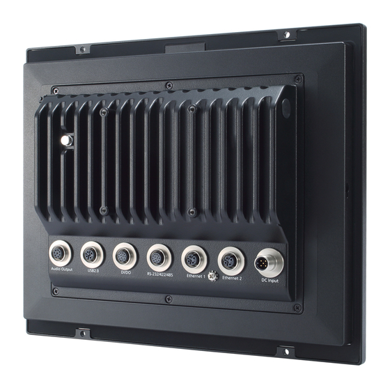
Page 9: Rear View
MPC-2121 HW UM Hardware Introduction Rear View Right-side View... -
Page 10: Ambient Light Sensor
Hardware Introduction Ambient Light Sensor The MPC-2121 comes with an ambient light sensor located on the upper part of the front panel. This sensor helps automatically adjust the brightness of the panel with the ambient light conditions. The light sensor index is divided into 8 levels from L1 to L8; the lower the sensor index, the darker the panel. -
Page 11: Dimensions
MPC-2121 HW UM Hardware Introduction Dimensions... -
Page 12: Hardware Connection Description
Panel Mounting Front-panel Mounting Rear-panel Mounting Wiring Requirements Temperature Requirements Grounding the MPC-2121 Powering On/Off the MPC-2121 Display-control Buttons Connector Description DC Power Input Serial Ports Ethernet Ports ... -
Page 13: Panel Mounting
Front-panel Mounting The MPC-2121 can also be mounted using the front panel. Use the four screws on the front panel to attach the front panel of the computer to a wall. Refer to the following figures for the location of the screws. -
Page 14: Rear-Panel Mounting
Hardware Connection Description Rear-panel Mounting A panel-mounting kit consisting of 6 mounting units is provided in the MPC-2121 package. Refer to the following illustrations for the dimensions and the cabinet space required to panel mount the MPC-2121. To install the panel-mounting kit on the MPC-2121, follow these steps: 1. - Page 15 MPC-2121 HW UM Hardware Connection Description 2. Use a torque of 4Kgf-cm to fasten the mounting screws and secure the panel-mounting kit onto a wall.
-
Page 16: Wiring Requirements
Grounding the MPC-2121 Before you power on the MPC-2121, connect it to a well-grounding metal surface. Grounding and wire routing help limit the effects of noise due to electromagnetic interference (EMI). Run the ground connection from the ground screw to the grounding surface prior to connecting the power. -
Page 17: Powering On/Off The Mpc-2121
To power off the MPC-2121, we recommend using the "shut down" function provided by the OS installed on the MPC. If you use the Power button, you may enter one of the following states depending on the power management settings in the OS: standby, hibernation, or system shutdown mode. -
Page 18: Connector Description
Hardware Connection Description ATTENTION The MPC-2121 comes with a 1000-nit display, the brightness level of which is adjustable up to level 10. The display is optimized for use in the -40 to 70°C temperature range. However, if you are operating the MPC-2121 at an ambient temperature of 60°C or higher, we recommend setting the brightness level of the display to 8 or... -
Page 19: Ethernet Ports
Definition USB- Power USB+ Audio Port The MPC-2121 comes with an audio output port with an M12 connector. Refer to the following figure for the pin definitions. Definition Detect Line out _L Line out _R Speaker out-... -
Page 20: Dio Port
Hardware Connection Description DIO Port The MPC-2121 is provided with a DIO port, which is an 8-pin M12 connector that includes 4 DIs and 2 DOs. For the DI and DO wiring instructions, refer to the following diagrams and pin assignment table. - Page 21 MPC-2121 HW UM Hardware Connection Description To install the storage devices, do the following: 1. Remove the two screws on the storage-socket cover. The top slot is for the CFast card while the lower slot is for the SD card, as indicated by the following illustration: 2.
- Page 22 MPC-2121 HW UM Hardware Connection Description SD Card 3. Reattach the cover and secure it with screws. 3-11...
-
Page 23: Bios Settings
BIOS Settings In this chapter, we describe the BIOS settings for the MPC-2121 embedded computer. The BIOS is a set of input/output control routines for peripherals. The BIOS is used to initialize basic peripherals and helps boot the operating system before the operating system is loaded. The BIOS setup allows the user to modify the system configurations of these basic input/output peripherals. -
Page 24: Entering The Bios Setup
MPC-2121 HW UM BIOS Settings Entering the BIOS Setup To enter the BIOS setup utility, press the F2 key while the system is booting up. The main BIOS Setup screen appears with the following options: • Continue: Continue to boot up Boot Manager: Select the device to boot up •... -
Page 25: Basic System Information
MPC-2121 HW UM BIOS Settings Basic System Information The main page shows basic system information, such as the model name, BIOS version, and CPU type. NOTE The “Processor Type” varies depending on the product model. Advanced Settings The Advanced screen appears when you select “Advanced” from the main menu. -
Page 26: Boot Configuration
MPC-2121 HW UM BIOS Settings Boot Configuration This screen allows you to configure the initial status of the Numlock key when the computer boots up. Options: On (default), Off PCI Express Configuration PCIE PORT 1 Speed Configures the speed of the PCIe Port 1. -
Page 27: Usb Configuration
MPC-2121 HW UM BIOS Settings USB Configuration USB Port #0 Enable or disable the USB port 0; if disabled, the system won’t detect a USB device that is plugged in. Options: Enabled (default), Disabled SD Configuration SDR25 Capability Support for SD Card Set the input/output timing for the SDR25 mode. -
Page 28: Miscellaneous Configuration
MPC-2121 HW UM BIOS Settings DDR50 Capability Support for SD Card Set the input/output timing for the DDR50 mode. Options: Disabled (default), Enabled Miscellaneous Configuration Light Sensor LED Use this setting to control the light sensor when the system is running. -
Page 29: Sata Configuration
MPC-2121 HW UM BIOS Settings SATA Configuration Chipset SATA Mode Select the SATA mode Options: AHCI (default), IDE SATA Speed Select the speed of the SATA drive. Options: Gen1 (default), Gen2... -
Page 30: Console Redirection
MPC-2121 HW UM BIOS Settings Console Redirection Console Serial Redirect When the Console Redirection function is enabled, the console information will be output both to the HDMI monitor and through the serial port. Options: Disabled (default), Enabled ACPI SPCR Table... -
Page 31: Hardware Monitor
±5% of the actual readings. However, the temperature readings are only valid when the ambient temperature is above 0°C. Smart Recovery Info This screen shows the Smart Recovery information. Load Smart Recovery Default This function allows you to load the default Smart Recovery value to the MPC-2121 panel computer. -
Page 32: Security Settings
MPC-2121 HW UM BIOS Settings Security Settings This screen allows you to configure a supervisor password. Set Supervisor Password This setting allows you to set the supervisor password. To set a new password, type in the password and then retype the password again to confirm. -
Page 33: Power Settings
MPC-2121 HW UM BIOS Settings Power Settings This screen allows you to configure the power settings. ACPI S3 S4 This setting allows you to select both Sleep Mode and Hibernate Mode in the Windows system. Options: Disabled (default), Enabled. Wake on LAN This setting allows you to wake the system up over the LAN from a remote host. -
Page 34: Boot Settings
MPC-2121 HW UM BIOS Settings Boot Settings This screen allows you to configure boot up settings. Boot Type The system will be based on the value used to build the boot environment for different types of operating systems. Options: Dual Boot Type (default), Legacy Boot Type, UEFI Boot Type PXE Boot to LAN This setting allows you to enable or disable the PXE boot to LAN function. -
Page 35: Usb Boot
MPC-2121 HW UM BIOS Settings USB Boot This setting allows you to enable or disable the USB boot function. Options: Enabled (default), Disabled Boot Delay Time This setting allows you to configure the delay time to enter a hot key during POST operations. -
Page 36: Exit Settings
MPC-2121 HW UM BIOS Settings Exit Settings This screen shows the various options to exit from the BIOS setup utility. Exit Saving Changes This option allows you to exit the BIOS setup utility and save the values you have just configured. -
Page 37: Save Custom Defaults
MPC-2121 HW UM BIOS Settings Save Custom Defaults This option allows you to save the current BIOS settings as a “custom default” that you can load at any time using the “Load Custom Defaults” option. Options: Yes (default), No Discard Changes This option allows you to discard all settings you have just configured. - Page 38 The file name should be in the format: MPC-21211xxx.exe (where “xxx” refers to the version numbers). 2. Copy the file to the bootable USB drive. Step 3: Run the Upgrade Program on the MPC-2121 Computer 1. Reboot the computer, and press F2 during the booting process to display the Boot Manager.
- Page 39 2. Select USB Disk as the first boot source and press [Enter] to continue. 3. When the computer finishes booting up, a command window appears. Go to the directory where the upgrade file is located. For example, if the upgrade file is stored in the MPC-2121 folder, type cd MPC-2121.
- Page 40 MPC-2121 HW UM BIOS Settings 6. When the upgrade is finished, the computer automatically reboots. You may check the BIOS version on the Main page of the BIOS setup utility. BIOS Version V1.00S10 Project Name MPC-2121 4-18...
-
Page 41: Display Resolution
Display Resolution This chapter describes how to install the graphics driver for your MPC-2121. After installing the driver, you will be able to use the graphic tools described here to adjust the display resolution of your panel computer. The following topics are covered in this chapter: ... -
Page 42: Installing The Graphics Driver
Display Resolution Installing the Graphics Driver A stock graphics driver for Windows Embedded Standard 7 is available for download from the MPC-2121 product page on Moxa’s website. To install the driver, do the following: 1. Browse to the Driver folder and open the MPC-2121-W7E_V1.0_Driver_Perpheral folder. - Page 43 MPC-2121 HW UM Display Resolution 4. In the installation wizard that opens up, click Next to continue. 5. Click Next to start the installation process.
- Page 44 MPC-2121 HW UM Display Resolution 6. Click Yes to accept the license agreement. 7. Click Next to continue with the installation.
- Page 45 MPC-2121 HW UM Display Resolution 8. Wait until the installation is completed. 9. Click Next to continue with the setup process.
-
Page 46: Adjusting The Display Resolution
Display Resolution 10. Select Yes, I want to restart this computer now and then click Finish to exit from the wizard. After your MPC-2121 reboots, you can use the Intel graphics tool to adjust the display resolution. Adjusting the Display Resolution Follow these steps to adjust the display resolution of your MPC-2121: 1. - Page 47 MPC-2121 HW UM Display Resolution 3. Select Maintain Display Scaling to maximize the display so that it fits the screen. 4. Click Apply.
-
Page 48: Serial Port Driver And Utility
Serial Port Driver and Utility This chapter describes how to install the serial port driver. After installing the drivers, you can configure the serial interface mode (RS-232/422/485) for the software selectable serial port. The following topics are covered in this chapter: ... -
Page 49: Overview
Serial Port Driver and Utility Overview The MPC-2121 supports the following serial modes: RS-232, RS-422, 2-wire RS-485, and 4-wire RS-485. These modes can be configured on COM1 and COM2. Before you do configuration the serial port, you should install the “MxGeneralIo”... - Page 50 MPC-2121 HW UM Serial Port Driver and Utility 3. Select the second item Install the hardware that I manually select from a list (Advanced) and click Next 4. Click Next...
- Page 51 MPC-2121 HW UM Serial Port Driver and Utility 5. Select Have Disk… 6. Point to the path Driver\MPC-2121-W7E_V1.0_Driver_Perpheral\4.MxGeneralIO\x64 and select MxGeneralIo.inf...
- Page 52 MPC-2121 HW UM Serial Port Driver and Utility 7. Select Next 8. Select Next...
-
Page 53: Installing The Serial Interface Utility
MPC-2121 HW UM Serial Port Driver and Utility 9. Select Finish 10. Double check if the driver has successfully installed. Installing the Serial Interface Utility Complete the following steps to install the SerialInterface utility: 1. The SerialInterface setup *.exe file can be found on the product DVD: <Software DVD>\Utility\MPC-2121_SerialInterface\ to. - Page 54 MPC-2121 HW UM Serial Port Driver and Utility 2. Click Next to continue. The default destination folder is C:\Program Files(x86)\Moxa\ SerialInterface. 3. Click Install to continue.
-
Page 55: Configuring The Serial Interface Mode
MPC-2121 HW UM Serial Port Driver and Utility 4. Click Finish to complete the installation process and reboot the computer. Configuring the Serial Interface Mode Complete the following steps to configure the interface mode: 1. From the Start menu, Click All Programs Moxa mxSetSerialInterface. - Page 56 MPC-2121 HW UM Serial Port Driver and Utility 2. Select a port (COM1 or COM2). 3. Select the mode that you want to use for the port selected in the previous step. 4. Click OK...
-
Page 57: Regulatory Approval Statement
Regulatory Approval Statement This device complies with part 15 of the FCC Rules. Operation is subject to the following two conditions: (1) This device may not cause harmful interference, and (2) this device must accept any interference received, including interference that may cause undesired operation.
Need help?
Do you have a question about the MPC-2121 and is the answer not in the manual?
Questions and answers