
Related Manuals for Moxa Technologies MPC-2070


Summary of Contents for Moxa Technologies MPC-2070
- Page 1 MPC-2070 Panel Computer Hardware User’s Manual Edition 1.0, August 2017 www.moxa.com/product © 2017 Moxa Inc. All rights reserved.
-
Page 2: Copyright Notice
MPC-2070 Panel Computer Hardware User’s Manual The software described in this manual is furnished under a license agreement and may be used only in accordance with the terms of that agreement. Copyright Notice © 2017 Moxa Inc. All rights reserved. -
Page 3: Table Of Contents
VESA Mounting ........................... 3-3 Wiring Requirements ........................... 3-3 Temperature Requirements ........................3-4 Grounding the MPC-2070 Series ......................3-4 Powering On/Off the MPC-2070 Series ....................3-4 Display-Control Buttons ........................3-5 Connector Description ......................... 3-6 DC Power Input ........................... 3-6 Serial Ports ..........................3-6 Ethernet Ports .......................... - Page 4 Serial Port Driver and Utility ......................6-1 Overview ............................6-2 Installing the MxGeneralIO Driver ......................6-2 Installing the SerialInterface Utility ....................... 6-6 Configuring the Serial Interface Mode ....................6-8 Regulatory Approval Statement ......................A-1...
-
Page 5: Introduction
Introduction In this chapter, we give a general introduction to the features and specifications of MPC-2070 panel computers. The following topics are covered in this chapter: Overview Ordering Information Package Checklist Product Features MPC-2070 Hardware Specifications... -
Page 6: Overview
IT communications, all with native network redundancy. The MPC-2070 Series panel computers are designed with a wide, -40 to 70°C temperature range, and come with a fanless, streamlined enclosure designed for highly efficient heat dissipation, making this one of the most reliable industrial platforms available for harsh, hot, outdoor environments like oil and gas fields, or drilling platforms. -
Page 7: Product Features
MPC-2070 Hardware Introduction Product Features The MPC-2070 Series panel computer has the following features: • 7-inch panel computer • Intel® Atom™ Processor E3826 1.46GHz • -40 to 70°C wide-temperature design, no fan/no heater • 1000-nit sunlight-readable LCD • Glove-friendly and multi-touch screen •... - Page 8 MPC-2070 Hardware Introduction Physical Characteristics Housing: Aluminum sheet metal Weight: 1.40 kg (3.09 lb) Dimensions: 200 x 140 x 45 mm (7.9 x 5.5 x 1.8 in) Mounting: VESA mount (50 x 75 mm), and panel mount System Cooling: Fanless thermal design Environmental Limits Operating Temperature: -40 to 70°C (-40 to 158°F)
-
Page 9: Hardware Introduction
Hardware Introduction The MPC-2070 Series computer is compact, well-designed, and ruggedized for industrial applications. Multiple serial ports allow you to connect different devices for data operation, and the reliable and stable hardware platform lets you devote your attention to developing your applications. -
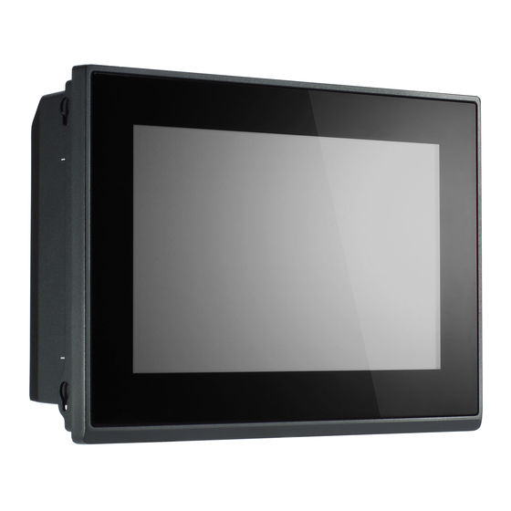
Page 10: Appearance
MPC-2070 Hardware Hardware Introduction Appearance Front View Bottom View... -
Page 11: Dimensions
MPC-2070 Hardware Hardware Introduction Dimensions... -
Page 12: Hardware Connection Description
The following topics are covered in this chapter: Panel Mounting VESA Mounting Wiring Requirements Temperature Requirements Grounding the MPC-2070 Series Powering On/Off the MPC-2070 Series Display-Control Buttons Connector Description DC Power Input Serial Ports Ethernet Ports ... -
Page 13: Panel Mounting
The maximum thickness of the surface to which the computer will be clamped is 4.6 mm. For a secure mounting, all 6 clamps must be used. The clamp arms are fastened into slots on all four sides of the MPC-2070. Use the short M4 SUS (stainless) screws to fasten the clamp arms to the MPC-2070 mounting slots, as shown in the diagram below. -
Page 14: Vesa Mounting
VESA Mounting The MPC-2070 is provided with VESA mounting holes on the back panel, which you can use directly without the need for an adapter. The dimension of the VESA mounting area is 50 x 75 mm. You will require four M4 x 6mm screws to mount the MPC-2070. -
Page 15: Temperature Requirements
To power off the MPC-2070, we recommend using the "shut down" function provided by the OS installed on the MPC. If you use the Power button, you may enter one of the following states depending on the power management settings in the OS: standby, hibernation, or system shutdown mode. -
Page 16: Display-Control Buttons
Manually decrease the brightness of the panel ATTENTION The MPC-2070 Series comes with a 1000-nit display, the brightness level of which is adjustable up to level 10. The display is optimized for use in the -40 to 70°C temperature range. However, if you are operating the MPC-2070 at an ambient temperature of 60°C or higher, we recommend setting the brightness level of the... -
Page 17: Connector Description
The terminal block is available in the accessories package. The DC pin assignments are show in the figure. Serial Ports The MPC-2070 offers two software-selectable RS-232/422/485 serial ports over a DB9 connector. The pin assignments for the ports are shown in the table below: RS-485 RS-485... -
Page 18: Usb Ports
Four USB 2.0 ports are available on the bottom panel. Use these ports to connect mass storage drives and other peripherals. DIO Port The MPC-2070 is provided with a DIO port, which is a 10-pin terminal block that includes 4 DIs and 4 DOs as illustrated in the diagram. Installing a CFast or SD Card MPC-2070 provides two storage options—CFast and SD card. - Page 19 MPC-2070 Hardware Hardware Connection Description 2. Insert the CFast or SD card into the slot using the push-push mechanism. 3. Reattach the cover and secure it with screws.
-
Page 20: Bios Settings
BIOS Settings In this chapter, we describe the BIOS settings for the MPC-2070 embedded computer. The BIOS is a set of input/output control routines for peripherals. The BIOS is used to initialize basic peripherals and helps boot the operating system before the operating system is loaded. The BIOS setup allows the user to modify the system configurations of these basic input/output peripherals. -
Page 21: Entering The Bios Setup
MPC-2070 Hardware BIOS Settings Entering the BIOS Setup To enter the BIOS setup utility, press the F2 key while the system is booting up. The main BIOS Setup screen appears with the following options: • Continue: Continue to boot up Boot Manager: Select the device to boot up •... -
Page 22: Basic System Information
MPC-2070 Hardware BIOS Settings Basic System Information The main page shows basic system information, such as the model name, BIOS version, and CPU type. NOTE The “Processor Type” varies depending on the product model. Advanced Settings The Advanced screen appears when you select “Advanced” from the main menu. -
Page 23: Boot Configuration
MPC-2070 Hardware BIOS Settings Boot Configuration This screen allows you to configure the initial status of the Numlock key when the computer boots up. Options: On (default), Off PCI Express Configuration PCIE PORT 1 Speed Configure PCIe Port1 Speed Options: Auto, Gen1 and Gen2... -
Page 24: Usb Configuration
MPC-2070 Hardware BIOS Settings USB Configuration USB Port #0 Enable or Disable the USB port 0; if disabled, the system won’t detect when a USB device is plugged in. Option: Enabled (default), Disabled USB Port #1 Enable or Disable the USB port 1; if disabled, the system won’t detect when a USB device is plugged in. -
Page 25: Sd Configuration
MPC-2070 Hardware BIOS Settings SD Configuration SDR25 Capability Support for SD Card Set Input/output timing for SDR25 mode. Option: Enabled (default), Disabled DDR50 Capability Support for SD Card Set Input/output timing for DDR50 mode. Option: Disabled (default), Enabled... -
Page 26: Miscellaneous Configuration
MPC-2070 Hardware BIOS Settings Miscellaneous Configuration Power Button Light Use this setting to control the power button light when the system is running. Options: Enable(default), Disable. Power ON after Power Failure This setting allows you to configure whether or not the computer should automatically boot up when the power is re-applied after a power failure. -
Page 27: Sata Configuration
MPC-2070 Hardware BIOS Settings DO-2 Level This item allows you set the DO 2 as high or low Options: High (default), Low DO-3 Level This item allows you set the DO 3 as high or low. Options: High (default), Low... -
Page 28: Console Redirection
MPC-2070 Hardware BIOS Settings Console Redirection Console Serial Redirect When the Console Redirection Function is enabled, the console information will be output to both the HDMI monitor and through the serial port. Options: Disabled (default), Enabled ACPI SPCR Table This table is used to indicate whether a serial port or a non-legacy UART (Universal Asynchronous Receiver/Transmitter) interface is available for use with Microsoft Windows Emergency Management Services (EMS). -
Page 29: Hardware Monitor
MPC-2070 Hardware BIOS Settings Hardware Monitor This screen allows you to view voltage levels, system temperature, and CPU temperature. Note that the voltage values vary depending on the model. The temperature readings shown on the screen are within ±5% of the actual readings. However, the temperature readings are only valid when the ambient temperature is above 0°C. -
Page 30: Set Supervisor Password
MPC-2070 Hardware BIOS Settings Set Supervisor Password This setting allows you to set the supervisor password. Type a new password and then retype the password again to confirm. To delete the password, enter the existing password in the Set Supervisor Password field and leave the new password field blank;... -
Page 31: Auto Wake On S5
MPC-2070 Hardware BIOS Settings Auto Wake on S5 This setting allows you to configure the computer to wake from the S5 (Soft Off) state where the power supply remains engaged but is not supplying power to all other parts of the system. -
Page 32: Boot Type
MPC-2070 Hardware BIOS Settings Boot Type The system will be based on the value used to build the boot environment for different types of operating systems. Options: Dual Boot Type (default), Legacy Boot Type, UEFI Boot Type PXE Boot to LAN This setting allows you to enable or disable the PXE boot to LAN function. -
Page 33: Legacy
MPC-2070 Hardware BIOS Settings Legacy Normal Boot Menu This setting allows you to configure the boot order. To change the boot order, press the “-” or “F5” key to move down to an item in the list, and the “+” or “F6” key to move up. -
Page 34: Exit Discarding Changes
MPC-2070 Hardware BIOS Settings Exit Discarding Changes This option allows you to exit without saving that changes that might have been made to the BIOS. Options: Yes (default), No Load Optimal Defaults This option allows you to revert to the factory default BIOS values. - Page 35 MPC-2070 Hardware BIOS Settings 1. Start Rufus* and then in the “Device” drop-down list select the USB device that you want to use as a bootable disk. *Rufus official website: https://rufus.akeo.ie/?locale=en_US 2. Select MBR partition scheme for BIOS or UEFI computers from the “Partition scheme and target...
- Page 36 MPC-2070 Hardware BIOS Settings Step 3: Run the Upgrade Program on the MPC-2070 Computer 1. Reboot the computer, and press F2 during the booting process to display the Boot Manager. 2. Select USB Disk as the first boot source and press [Enter] to continue.
- Page 37 BIOS Settings 3. When the computer finishes booting up, a command window appears. Go to the directory where the upgrade file is located. For example, if the upgrade file is stored in the MPC-2070 folder, type cd MPC-2070. C:\cd MPC-2070 4.
-
Page 38: Display Resolution
Display Resolution This chapter describes how to install the graphics driver for your MPC-2070. After installing the driver, you will be able to use the graphic tools described here to adjust the display resolution of your panel computer. The following topics are covered in this chapter: ... -
Page 39: Installing The Graphics Driver
Display Resolution Installing the Graphics Driver A stock graphics driver for Windows Embedded Standard 7 is available for download from the MPC-2070 product page on Moxa’s website. To install the driver, do the following: 1. Browse to the Driver folder and open the MPC-2070-W7E_V1.0_Driver_Perpheral folder. - Page 40 MPC-2070 Hardware Display Resolution 4. In the installation wizard that opens up, click Next to continue. 5. Click Next to start the installation process.
- Page 41 MPC-2070 Hardware Display Resolution 6. Click Yes to accept the license agreement. 7. Click Next to continue with the installation.
- Page 42 MPC-2070 Hardware Display Resolution 8. Wait until the installation is completed. 9. Click Next to continue with the setup process.
-
Page 43: Adjusting The Display Resolution
Display Resolution 10. Select Yes,I want to restart this computer now and then click Finish to exit from the wizard. After your MPC-2070 reboots, you can use the Intel graphics tool to adjust the display resolution. Adjusting the Display Resolution Follow these steps to adjust the display resolution of your MPC-2017: 1. - Page 44 MPC-2070 Hardware Display Resolution 3. Select Maintain Display Scaling to maximize the display so that it fits the screen. 4. Click Apply.
-
Page 45: Serial Port Driver And Utility
Serial Port Driver and Utility This chapter describes how to install the serial port driver. After installing the drivers, you can configure the serial interface mode (RS-232/422/485) for the software selectable serial port. The following topics are covered in this chapter: ... -
Page 46: Overview
Serial Port Driver and Utility Overview The MPC-2070 supports the following serial modes: RS-232, RS-422, 2-wire RS-485, and 4-wire RS-485. These modes can be configured on COM1 and COM2. Before you do configuration the serial port, you should install the “MxGeneralIO”... - Page 47 MPC-2070 Hardware Serial Port Driver and Utility 3. Select the second item Install the hardware that I manually select from a list (Advanced) and click Next 4. Click Next...
- Page 48 MPC-2070 Hardware Serial Port Driver and Utility 5. Select Have Disk… 6. Point to the path Driver\MPC-2070-W7E_V1.0_Driver_Perpheral\4.MxGeneralIO\x64 and select MxGeneralIo.inf...
- Page 49 MPC-2070 Hardware Serial Port Driver and Utility 7. Select Next 8. Select Next...
-
Page 50: Installing The Serialinterface Utility
MPC-2070 Hardware Serial Port Driver and Utility 9. Select Finish 10. Double check if the driver has successfully installed. Installing the SerialInterface Utility Complete the following steps to install the SerialInterface utility: 1. The SerialInterface setup *.exe file can be found on the product DVD: <Software DVD>\Utility\MPC-2070_SerialInterface\ to. - Page 51 MPC-2070 Hardware Serial Port Driver and Utility 2. Click Next to continue. 3. The default destination folder is C:\Program Files(x86)\Moxa\Mxsp; click Install to continue.
-
Page 52: Configuring The Serial Interface Mode
MPC-2070 Hardware Serial Port Driver and Utility 4. Click Finish to complete installation. Configuring the Serial Interface Mode Complete the following steps to configure the interface mode: 1. From the Start menu, Click All Programs Moxa mxSetSerialInterface. - Page 53 MPC-2070 Hardware Serial Port Driver and Utility 2. Select a port (COM1 or COM2). 3. Select the mode that you want to use for the port selected in the previous step. 4. Click OK...
-
Page 54: Regulatory Approval Statement
Regulatory Approval Statement This device complies with part 15 of the FCC Rules. Operation is subject to the following two conditions: (1) This device may not cause harmful interference, and (2) this device must accept any interference received, including interference that may cause undesired operation.
Need help?
Do you have a question about the MPC-2070 and is the answer not in the manual?
Questions and answers