Table of Contents
Advertisement
Quick Links
Introduction
Marine
generator sets
Operator's manual
7 GSC
8 GSAC
8 GTC
10 GTAC
10 GSC
12 GSAC
11 GTC
14 GTAC
14 GSC
17 GSAC
17 GTC
20 GTAC
U_GBAV_EN
Revision 7
Solé, S.A. C-243 b, km 2 · 08760 Martorell (Barcelona) ·Tel. +34 93 775 14 00 · www.solediesel.com · info@solediesel.com
Operator's Manual Marine Diesel Gensets
2
Advertisement
Table of Contents

Subscribe to Our Youtube Channel
Related Manuals for Sole Diesel 7 GSC


Summary of Contents for Sole Diesel 7 GSC
- Page 1 Introduction Marine generator sets Operator’s manual 7 GSC 8 GSAC 8 GTC 10 GTAC 10 GSC 12 GSAC 11 GTC 14 GTAC 14 GSC 17 GSAC 17 GTC 20 GTAC U_GBAV_EN Revision 7 Solé, S.A. C-243 b, km 2 · 08760 Martorell (Barcelona) ·Tel. +34 93 775 14 00 · www.solediesel.com · info@solediesel.com...
-
Page 3: Introduction
Introduction Introduction Presentation Dear Customer, First, we would like to thank you for choosing a Solé Diesel product. We recommend that you read this manual carefully before carrying out any of the operations and keep it close at hand, near the genset, as it can be of great use in the future. -
Page 4: Table Of Contents
Table of contents Table of contents Introduction ..............................2 Table of contents ............................3 Safety precautions and instructions......................4 Engine labels .............................. 6 Solé Diesel warranty ........................... 7 Solé Diesel limited warranty ........................7 Solé Diesel extended warranty ......................7 Restrictions ............................. - Page 5 Table of contents Circuit description ..........................23 Oil specifications ..........................23 Maintenance task. Oil filter change....................23 Maintenance task. Oil level check ....................24 Maintenance task. Oil fill / change ....................24 Circuit description ..........................25 Fuel specifications ..........................25 Maintenance task.
-
Page 6: Table Of Contents
Table of contents 6.1. Installation ..........................36 6.2. Operator interface SCO 10 ..................... 37 Genset operator indicators ......................38 Displays and control button ......................38 6.3. Display Screens and Pages Structure ..................38 Measurement ........................... 39 Setpoint. Controller information screen ..................41 Set point. -
Page 7: Safety Precautions And Instructions
Safety precautions and instructions Safety precautions and instructions Solé Diesel is concerned for your safety and your machine’s condition. Safety Precautions and Instructions are one of the primary ways to call your attention to the potential hazards associated with our engine operation. Follow the precautions listed throughout the manual before and during operation and maintenance procedures for your safety, the safety of others and the performance of your engine. -
Page 8: Solé, S.a. C-243 B, Km 2 · 08760 Martorell (Barcelona) ·Tel. +34 93 775 14 00 · Www.solediesel.com · Info@Solediesel.com
Safety precautions and instructions Get fresh air and do not sit, lie down or fall asleep if anyone shows signs of carbon monoxide poisoning: - Light-headedness, dizziness - Physical fatigue, weakness in joints and muscles. Sleepiness, mental fatigue, inability to concentrate or speak clearly, blurred vision. Stomachache, vomiting, nausea. -
Page 9: Engine Labels
Solé Diesel Warranty Engine labels If the engine does not start after several attempts to crank may cause water entering the engine. In this situation it is recommended: 1) Close the seacock. 2) Drain the water from the exhaust system in the water trap. 3) Do not try to restart the engine until the cause of the start fail is identified. -
Page 10: Solé Diesel Warranty
Solé Diesel Warranty Solé Diesel warranty Read the manual and documents delivered with each engine before carrying out any of the operations or presenting any queries. The engine is supplied without any liquids. Ensure that the liquids used match the specifications contained in Solé Diesel manuals. The application of the conditions described in this document shall only be effective for engines or generator sets that have been invoiced after January 1, 2012. -
Page 11: Responsibilities
Solé Diesel Warranty Excluded from coverage: a) If Solé Diesel products are installed and used alongside other products not designed or manufactured by Solé Diesel that affect their operation, the warranty shall apply exclusively to the Solé Diesel products and shall not apply if the products from another manufacturer are inappropriate for use alongside Solé... -
Page 12: After-Sales Service Contact
Solé Diesel Warranty Responsibilities of the purchaser: The purchaser shall be responsible for the care, operation and maintenance of the product in compliance with the contents of the User and Maintenance Manuals. The purchaser shall provide proof of all the maintenance services performed on the product. The costs of said services and that of the components and liquids replaced during said services shall be at the expense of the purchaser. -
Page 13: Section 1 - Genset Information
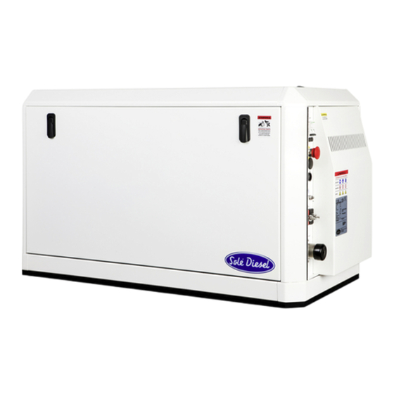
Genset information Section 1 - Genset Information 1.1. Genset Identification IDENTIFICATION LABEL: The nameplate is located above the rocker cover. The characteristics plate of genset it’s located above the alternator case. The characteristics plate of canopy genset it’s located outside, as shown in the following picture: GENSET SERIAL NUMBER: In addition, all gensets are marked with the serial number on the block, on the fuel injection pump. -
Page 14: Genset Parts Identification
Glow plug Anti-vibration mounts Regulator support box¹ ¹ Only for 7 GSC and 8 GSAC gensets Solé, S.A. C-243 b, km 2 · 08760 Martorell (Barcelona) ·Tel. +34 93 775 14 00 · www.solediesel.com · info@solediesel.com Operator’s Manual. Marine generator sets... - Page 15 Genset information Gensets: 14 GSC / 14 GTAC / 17 GASAC / 17 GTC / 20 GTAC PIECE ELEMENT Oil filter Oil level stick Oil fill cap Oil drain tube Fuel filter Relays Fuel feed pump Electric fuel feed pump 12V Nozzles Air inlet elbow Wet exhaust elbow...
-
Page 16: Section 2 - Transport, Handling And Storage
Transport, handing and storage Section 2 - Transport, Handling and Storage 2.1. Reception When the genset is delivered make sure that the packing has not been damaged during transport and that it has not been tampered with or that components inside the packing have been removed (see information marked on covers, bases and cartons). -
Page 17: Transporting And Handling The Unpacked Genset
For gensets 11GTC / 14GTAC / 10 GSC / 12 GSAC For gensets 8 GTC / 10 GTAC / 7 GSC / 8 GSAC / 17 GTC / 20 GTAC / 14 GSC / 17 GSAC 2.4. Storage of Packed and Unpacked Genset If the genset is left idle for prolonged periods, the client must check the possible conditions of conservation in relation to the place of storage. -
Page 18: Section 3 - Installation
Continuously Temporary 8 GTC / 10 GTAC / 7 GSC / 8 GSAC / 11 GTC / 14 GTAC / 10 GSC / 12 GSAC / 17 GTC / 20 GTAC / 14 GSC / 17 25º... -
Page 19: Section 4 - Operation
Operation Section 4 – Operation 4.1. Prestart Checklist Follow these checks and inspections to ensure the correct genset operation. In addition, some checks require verification after unit starts. AIR CLEANER: Check for a clean and installed air cleaner element to prevent unfiltered air from entering the genset. -
Page 20: Winterzation And Preservation
Operation 1. Use special low temperature coolant or suitable anti-freezing agent concentration. 2. Close the seawater cock, when the genset is stopped. Open the seawater filter cover and start the genset adding a mixture of freshwater and suitable anti-freezing agent concentration (see package labels) until the seawater circuit is filled completely. -
Page 21: Maintenance During The Storage
Operation 4.4. Maintenance during the storage During the long genset storage, it has to be stored inside a ventilated area and free of humidity. When the genset stay stopped for 3 months or more, inside parts can be oxidize and lost the oil film. -
Page 22: Section 5 - Systems And Scheduled Maintenance
Systems and scheduled maintenance Section 5 – Systems and Scheduled Maintenance 5.1. Operating Description Information of special tools required and basic safety precautions. Disassembly: Use the correct tools and instruments. Serious injury or damage to the genset can result from using the wrong tools and instruments. Use an overhaul stand or work bench if necessary. - Page 23 Systems and scheduled maintenance Intervals 1st 20h- Every Every Every Every Every 2 Inspection Item Daily Winter storage and Preservation 200h 400h 800h year years Screw tightening, fastening. Genset block. General Valve clearance. Exhaust gas, noise and vibrations. Compression pressure. Genset oil.
-
Page 24: General
Solé Diesel offers, for these genset models, a maintenance kit: On board spare parts Reference 8 GTC / 10 GTAC / 7 GSC / 8 GSAC / 11 GTC / 14 GTAC / 10 GSC / 12 GSAC / 17 GTC / 20... -
Page 25: Maintenance Task. Compression Pressure Inspection
Systems and scheduled maintenance Maintenance task. Compression pressure inspection Start by: 1- Make sure the genset oil level, air cleaner, starting motor and battery are well- conditioned. 2- Start the genset and allow it to warm up thoroughly, until 50ºC or more coolant temperature. -
Page 26: Lubrication System
Pressure relief valve * Oil circuit capacity (L) 8 GTC / 10 GTAC / 7 GSC / 8 GSAC 11 GTC / 14 GTAC / 10 GSC / 12 GSAC 17 GTC / 20 GTAC / 14 GSC / 17 GSAC... -
Page 27: Maintenance Task. Oil Level Check
Systems and scheduled maintenance Maintenance task. Oil level check Check the oil level in the crankcase daily or before each start-up to ensure that the level is between the upper (Max mark) and lower (Min mark) lines on the dipstick. To check the oil level: Remove the dipstick Wipe the dipstick end Reinsert inside the guide... -
Page 28: Circuit Description
Systems and scheduled maintenance 5.5. Fuel System Circuit description The fuel system is based on a fuel feed pump and an in-line mechanical injection pump. PIECE ELEMENT Fuel injection nozzle Fuel injection pipe Fuel leak-ok pipe Injection pump Feed pumps Fuel filter Tank (supplied as accessory) Fuel decanting filter (supplied as accessory) -
Page 29: Maintenance Task. Fuel Filter Change
Systems and scheduled maintenance Maintenance task. Fuel filter change Procedure to change the fuel filter: Close the fuel supply valve. Disconnect fuel pipes from the fuel filter. Remove fuel filter with a bell key. Place a new fuel filter. Reconnect fuel pipes from the fuel filter. Open the fuel supply valve. -
Page 30: Maintenance Task. Bleeding Air From The Fuel System
Systems and scheduled maintenance discharge must be finely and uniformly atomized. Any change is an indication of a bad nozzle. If the nozzle is bad, remove the tip from the nozzle and wash needle valve and body in clean washing solution. And if the nozzle is still bad after the tip has been washed, replace the tip. -
Page 31: Cooling System
Systems and scheduled maintenance 5.6. Cooling System The genset cooling system is based on coolant circulation controlled by centrifugal pump with thermostatic control and heat exchanger, where the coolant is refrigerated by sea water. Moreover, the exhaust manifold is cooled also by sea water. Coolant circuit description Seawater circuit description PIECE... -
Page 32: Maintenance Task. Coolant Fill / Change
Systems and scheduled maintenance Maintenance task. Coolant fill / change Drain off all the coolant by opening the two drain plugs, one in the heat exchanger and the other in the cylinder block. Close the drain plugs. Remove bleeding bolt of thermostat holder Refill to the hole in the tank cap with coolant Maintenance task. -
Page 33: Inlet And Exhaust System
Systems and scheduled maintenance 9. Lubricate the gasket with silicon grease and attach the gasket and cover plate to the seawater pump housing. 10. Open the seacock. 11. Start the genset and check for leaks. 5.7. Inlet and Exhaust System Exhaust circuit description There are two possible installations of the exhaust system. -
Page 34: Maintenance Task. Air Filter Inspection
Systems and scheduled maintenance Type 2 installation. When between water injection point of wet exhaust and waterline there is less than 150 mm or the point of injection is below waterline. W.L. L = MAX. 3000 mm The wet exhaust is the genset’s standard equipment. If you want dry exhaust, which is an optional equipment, contact with our dealers Maintenance task. -
Page 35: Electrical System
17 GTC / 20 GTAC 60973400.2S 60973400.2S.18 /(24V) Monophasic Genset Model 1500 rpm (50 Hz) 1800 rpm (60 HZ) Panel reference 7 GSC / 8 GSAC 60939230S 60939230S.18 10 GSC / 12 GSAC 60972230S 60972230S.18 14 GSC / 17 GSAC 60973230S 60973230S.18 Battery The minimum recommended capacity is from 60 - 80 Ah. -
Page 36: Circuit Protection
Genset Model 12 V 24 V 8 GTC / 10 GTAC / 7 GSC / 8 GSAC 11 GTC / 14 GTAC / 10 GSC / 12 GSAC / 17 GTC / 20 GTAC / 14 GSC / 17 GSAC Circuit protection AC Breaker interrupts the genset output in the event of an overload or short circuit. -
Page 37: Maintenance Task. Battery Level
Systems and scheduled maintenance An excessive tension may cause a quick wear of the belt and alternator bearings. Otherwise, if the belt is excessively loose or has oil and insufficient load, it can cause the belt to skid. Never adjust the belt tension with genset running or battery connected Maintenance task. -
Page 38: Maintenance Task. Cleaning And Lubrication
Systems and scheduled maintenance Maintenance task. Cleaning and lubrication Any kind of cleaning work must be carried out with the genset shutdown and the mains power shut off for the risk of severe hazard for persons and objects. Moreover, prior to approaching or touching the alternator, ensure that it is at room temperature. -
Page 39: Section 6 - Sco 10 Panel
SCO 10 Panel Section 6 – SCO 10 PANEL 6.1. Installation The controller is to be mounted onto the switchboard door. Requested cutout size is 175x115mm. Use the screw holders delivered with the controller to fix the controller into the door as described on the pictures below. -
Page 40: Operator Interface Sco 10
SCO 10 Panel 6.2. Operator interface SCO 10 POSITION BUTTON DESCRIPTION START button. Works in MAN mode only. Press this button to initiate the start sequence of the engine. STOP button. Works in MAN mode only. Press this button to initiate the stop sequence of the genset. -
Page 41: Genset Operator Indicators
SCO 10 Panel Genset operator indicators POSITION DESCRIPTION Genset failure. Red LED starts flashing when genset failure occurs. After FAULT RESET button is pressed, the light steadies (if an alarm is still active) or turns off (if no alarm is active). -
Page 42: Measurement
SCO 10 Panel Measurement • Ready genset / No ready • Power factor (if the amperometric kit is installed). • • Timer seconds of each genes phase. • Active power pointer (if the amperometric kit is installed). • Voltage between phases and neutral. •... - Page 43 SCO 10 Panel Binary Inputs –Binary signals form the genset to the control panel. • BI1: Remote control – Start or Stop. • BI2: Alarm / Temperature switch (shutdown). • BI3: Emergency STOP. • BI4: Alarm / Pressure switch. BI5: Sd Override. •...
-
Page 44: Setpoint. Controller Information Screen
SCO 10 Panel Setpoint. Controller information screen Page Enter Hold the ENTER and PAGE button at the same time mismo tiempo. Page Page Page Enter If the panel is more than 5 seconds in a screen, it returns to initial screen automatically. In this case, you must begin all the procedure again. -
Page 45: Set Point. Maintenance Hours Change
SCO 10 Panel Set point. Maintenance hours change When the following warning appears in the Alarm list screen of SCO 10: First of all you must carry out the maintenance tasks according to the Maintenance task table, attached in the end. You also can consult this information in the Warranty manual. -
Page 46: History Log
SCO 10 Panel History log Page Page To display all the screens shown Enter below, you must press "ENTER" Solé, S.A. C-243 b, km 2 · 08760 Martorell (Barcelona) ·Tel. +34 93 775 14 00 · www.solediesel.com · info@solediesel.com Operator’s Manual. Marine generator sets... -
Page 47: Alarm List
SCO 10 Panel 6.4. Alarm list Fault Reset Active unconfirmed alarm Active confirmed alarm Alarm desactivation 6.5. Display contrast adjustment Enter Enter Hold ENTER button and, ↑ or ↓at the same time. Solé, S.A. C-243 b, km 2 · 08760 Martorell (Barcelona) ·Tel. +34 93 775 14 00 · www.solediesel.com · info@solediesel.com Operator’s Manual. -
Page 48: Change Language
SCO 10 Panel 6.6. Change language If the panel is more than 5 seconds in a screen, it returns to You must follow these steps to change the panel language. initial screen automatically. In this case, you must begin all the procedure again. -
Page 49: Alarm Management
SCO 10 Panel 6.7. Alarm Management The following alarms are available: • Breaker open and cooling (BOC) • Warning • Shut down Breaker open and cooling (BOC) When the control panel detects a problem related to the alternator. The panel stops the genset gradually. -
Page 50: Section 7 - Troubleshooting
Technical specifications Section 7 - Troubleshooting If a fault occurs in the genset, proceed as follows: ❖ Within the period of warranty: • Contact to Solé Diesel Official Service. See Solé Diesel WARRANTY. ❖ Outside the period of warranty: • Contact to Solé Diesel Official Service. See Solé Diesel WARRANTY. •... - Page 51 Technical specifications GENSET PROBABLE CAUSES RECOMMENDED ACTIONS SECTION FAILURE OFF mode Move to MAN mode. SCO 10 PANEL Replace the controller fuse. If the fuse blows again, Fuse (red wire) burned out troubleshoot the controller. Battery discharged or dead Recharge or replace the battery. FAILURE TO Battery connections loose, corroded or Verify that the battery connections are correct, clean and...
- Page 52 Technical specifications Fuel injection timing out of adjustment Adjust the fuel injection timing. Fuel tank empty or fuel valve shut off Add fuel and move the fuel valve to opened position. INLET EXHAUST Air filter clogged Replace air filter element. SYSTEM GENERAL Governor inoperative...
- Page 53 Technical specifications Increase speed by 15%. Apply a 12V voltage for an instant across the electronic regulator terminals using a battery with a 30 Ohm resistance in series and remember to respect the polarities. After the genset is excited it deactivates Check the wiring against the diagrams in appendix.
- Page 54 Technical specifications Compression weak Check the compression. GENERAL Overload Propeller too large, replace. Incorrect injection time Adjust the injection time of the injection pump. Faulty oil pump Contact with our dealer Check oil specifications (oil used must be chosen according LUBRICATION SYSTEM Oil viscosity too high to Technical Specifications).
- Page 55 Technical specifications Oil pressure relief valve sticking Contact with our dealer OIL PRESSURE LUBRICATION SYSTEM TOO HIGH Faulty oil pressure valve Contact with our dealer GENERAL Valve clearance incorrect Contact with our dealer Fuel filter clogged Contact with our dealer Fuel injectors dirty or faulty Contact with our dealer FUEL SYSTEM...
-
Page 56: Section 8 - Technical Specifications
18º ATDC 18º ATDC 10º ATDC Inlet and exhaust valve clearance - cold 0,25 genset (mm) 1500 (11 1500 (8 GTC) 1500 (7 GSC) GTC) RPM (rpm) 1800 (10 GTAC) 1800 (8 GSAC) 1800 (14 GTAC) Starting system Glow plugs... - Page 57 Insulation system Voltage variation (V) ± 1 Speed variation (rpm) -5% +3% GENSET 8,4 (11 GTC) 6,3 (8 GTC) 6,6 (7 GSC) Active stand-by power (kW) 10,9 (14 7,6 (10 GTAC) 8,0 (8 GSAC) GTAC) 10,5 (11 GTC) 7,8 (8 GTC)
- Page 58 Technical specifications 10 GSC 17 GTC 14 GSC 12 GSAC 20 GTAC 17 GSAC DIESEL ENGINE Type Water-cooled, Diesel 4-stroke cycle Direction of rotation Anti-clockwise observing genset from flywheel side Nº of cylinders – arrangement 3 – in line 4 – in line 4 –...
- Page 59 Technical specifications 10 GSC 17 GTC 14 GSC 12 GSAC 20 GTAC 17 GSAC DIESEL ENGINE End opening + 90 ºC Coolant temperature – nominal speed 75 - 85 (ºC) Air supple Air cleaning by means of a dry-type air filter Cooled exhaust manifold Dry exhaust manifold Exhaust System (optional equipament)
-
Page 60: Section 9 - Tightening Torques
Tightening torques Section 9 – Tightening Torques Important nuts and screws. 7 GTC / 10 GTAC / 7 GSC / 8 GSAC TIGHTENING VALUES THREAD N· m (kgf· m) Cylinder head 73.5 a 83.4 (7.5 a 8.5) Rocker arm cover 4.9 a 6.9 (0.5 a 0.7) -
Page 61: Section 10 - Technical Appendices
Technical appendices Section 10 – Technical Appendices Solé Diesel, S.A. C-243 b, km 2 · 08760 Martorell (Barcelona) ·Tel. +34 93 775 14 00 · www.solediesel.com · info@solediesel.com Operator’s Manual Marine Diesel Gensets... -
Page 62: Wiring Diagrams
Technical appendices 10.1. Wiring diagrams Solé Diesel, S.A. C-243 b, km 2 · 08760 Martorell (Barcelona) ·Tel. +34 93 775 14 00 · www.solediesel.com · info@solediesel.com Operator’s Manual Marine Diesel Gensets... - Page 63 DETALLE CONECTOR CPC PORTAMACHOS / DETAIL CONNECTOR CPC BOMBA DE ALIMENTACIÓN DE CUMBUSTIBLE DETALLE PIN L ALTERNADOR / DETAIL PIN L ALTERNATOR / FUEL FEED PUMP Precalentamiento Arranque Relé desconexión de tierra Preheating Cranking Earth disconnecting relay BB0A DETALLE RELE BUJIAS PRECALENTAMIENTO / PREHEATING RELAY DETALLE CONECTOR SOLENOIDE DE PARO / DETALLE RELE DE ARRANQUE / STARTER RELAY...
- Page 64 BOMBA DE ALIMENTACIÓN DE CUMBUSTIBLE DETALLE RELE DE ARRANQUE / Precalentamiento DETALLE RELE BUJIAS PRECALENTAMIENTO / PREHEATING RELAY Arranque Relé desconexión de tierra STARTER RELAY / FUEL FEED PUMP Preheating Cranking Earth disconnecting relay BB0A 85/86 Diodos 25 A DETALLE CONECTOR SOLENOIDE DE PARO / DETALLE PIN L ALTERNADOR / DETALLE CONECTOR CPC PORTAMACHOS / DETAIL CONNECTOR CPC DETAIL PIN L ALTERNATOR...
- Page 65 ARRANQUE / CRANKING DETALLE CONECTOR CPC PORTAMACHOS / DETAIL CONNECTOR CPC DETALLE PIN L ALTERNADOR / DETAIL PIN L ALTERNATOR OPT. BOMBA DE ALIMENTACIÓN DE CUMBUSTIBLE / STD. CANOPY FUEL FEED PUMP PARO DE EMERGENCIA DETALLE CONECTOR SOLENOIDE DE PARO / EMERGENCY STOP N.C.
- Page 66 ARRANQUE / CRANKING DETALLE CONECTOR CPC PORTAMACHOS / DETAIL CONNECTOR CPC DETALLE PIN L ALTERNADOR / DETAIL PIN L ALTERNATOR OPT. BOMBA DE ALIMENTACIÓN DE CUMBUSTIBLE / STD. CANOPY FUEL FEED PUMP PARO DE EMERGENCIA DETALLE CONECTOR SOLENOIDE DE PARO / EMERGENCY STOP N.C.
-
Page 67: Alternator Connections
Technical appendices 10.2. Alternator connections Solé Diesel, S.A. C-243 b, km 2 · 08760 Martorell (Barcelona) ·Tel. +34 93 775 14 00 · www.solediesel.com · info@solediesel.com Operator’s Manual Marine Diesel Gensets... - Page 68 COLLEGAMENTO - CONNECTIONS - CONNEXION - ANSCHLUSS - CONEXIÓN 12 morsetti - 12 wires - 12 klemmen - 12 bornes - 12 bornes...
- Page 69 COLLEGAMENTO - CONNECTIONS - CONNEXION - ANSCHLUSS - CONEXIÓN MONOFASE - SINGLE-PHASE - MONOPHASÉ - EINPHASIG - MONOFÁSICO...
-
Page 70: Regulator Connections
Technical appendices 10.3. Regulator connections Solé Diesel, S.A. C-243 b, km 2 · 08760 Martorell (Barcelona) ·Tel. +34 93 775 14 00 · www.solediesel.com · info@solediesel.com Operator’s Manual Marine Diesel Gensets... - Page 71 Estabilidad ST Tensión V Regulación de la subvelocidad UF Regulación de la Frecuencia BL4-U Alimentación Estator Excitador incremento de reducción de la tensión estabilidad reducción de incremento de tensión la estabilidad incremento del límite de de la subvelocidad reducción del límite de de la Conexion con un controlador, subvelocidad observar la polaridad:...
-
Page 72: Overall Dimensions
Technical appendices 10.4. Overall dimensions Solé Diesel, S.A. C-243 b, km 2 · 08760 Martorell (Barcelona) ·Tel. +34 93 775 14 00 · www.solediesel.com · info@solediesel.com Operator’s Manual Marine Diesel Gensets... - Page 73 176.5 SEA WATER OUTLET (Ø20) (ONLY DRY EXHAUST) SEA WATER INLET (Ø20) FUEL INLET (Ø8) Note: Dimensions inmillimeters FUEL OUTLET (Ø6) 8 GTC / 10 GTAC / 7 GSC / 8 GSAC GENSET MATERIAL ACABADO PRESENTACIÓN ESCALA TRATAMIENTO DIBUJADO FECHA CREACIÓN VERIFICADO GRADOPRECISIÓN...
- Page 74 (USE ONLY FOR A REFERENCE) VIEW E 387.5 107.5 8 x Ø16 MOUNTING HOLES VIEW D VIEW C FIRE EXTINGUISHER GENERATOR AIR INLET ACCESS HOLE AC BREAKER STAR/STOP SWITCH EMERGENCY STOP CUSTOMER LOAD LEAD ACCESS CUSTOMER PANEL CONNECTION EQUIPMENT GROUND CONNECTION BATTERY CONNECTIONS 105.5...
-
Page 76: Section 11 - Instructions To Replace And Remove
Instructions to replace and remove Section 11 - Instructions to Replace and Remove When you decide to replace the genset, please contact Solé Diesel S.A.; will provide relevant instructions regarding the laws in force at the time. When disposing of the whole or parts of this genset, meets LAWS IN FORCE IN THE COUNTRY OF INSTALLATION. -
Page 77: Section 12 - Inspection Prior To The Delivery Of Propulsion Engines
Inspection prior to the delivery of generator sets Section 12 – Inspection prior to the delivery of propulsion engines Solé Diesel, S.A. C-243 b, km 2 · 08760 Martorell (Barcelona) ·Tel. +34 93 775 14 00 · www.solediesel.com · info@solediesel.com Operator’s Manual Marine Diesel Gensets... - Page 78 Inspection prior to the delivery of generator sets Solé Diesel, S.A. C-243 b, km 2 · 08760 Martorell (Barcelona) ·Tel. +34 93 775 14 00 · www.solediesel.com · info@solediesel.com Operator’s Manual Marine Diesel Gensets...
-
Page 79: Maintenance Log
Maintenance log Maintenance log SERVICE DATE HOURS DESCRIPTION NAME Solé Diesel, S.A. C-243 b, km 2 · 08760 Martorell (Barcelona) ·Tel. +34 93 775 14 00 · www.solediesel.com · info@solediesel.com Operator’s Manual Marine Diesel Gensets... - Page 82 U_GBAV_EN Revision 7 04/2019...
Need help?
Do you have a question about the 7 GSC and is the answer not in the manual?
Questions and answers