Table of Contents
Advertisement
Quick Links
Introduction
Marine
generator sets
Operator's manual
G-8M-3
G-8T-3
G-15M-3
G-15T-3
G-25M-3
G-25M-3
U_CTGR1744_EN
Revision 1
U_GFAU_EN
Solé, S.A. C-243 b, km 2 · 08760 Martorell (Barcelona) ·Tel. +34 93 775 14 00 · www.soleDiesel.com · info@soleDiesel.com
Operator's Manual Marine Diesel Gensets
Revision 7
2
Advertisement
Table of Contents

Related Manuals for Sole Diesel G-8M-3


Summary of Contents for Sole Diesel G-8M-3
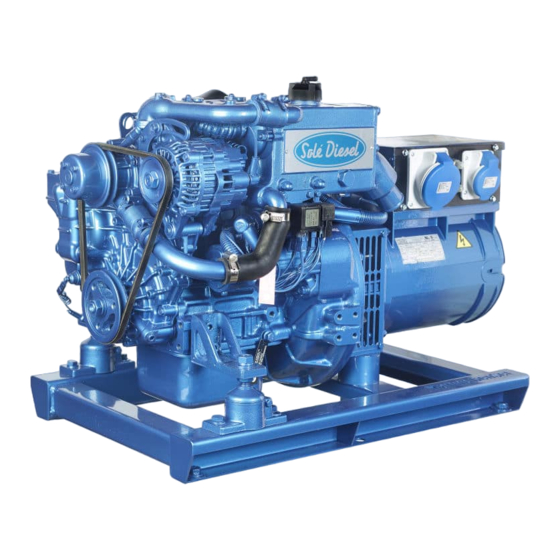
- Page 1 Introduction Marine generator sets Operator’s manual G-8M-3 G-8T-3 G-15M-3 G-15T-3 G-25M-3 G-25M-3 U_CTGR1744_EN Revision 1 U_GFAU_EN Solé, S.A. C-243 b, km 2 · 08760 Martorell (Barcelona) ·Tel. +34 93 775 14 00 · www.soleDiesel.com · info@soleDiesel.com Operator’s Manual Marine Diesel Gensets...
-
Page 3: Introduction
Introduction Introduction Presentation Dear Customer, First, we would like to thank you for choosing a Solé Diesel product. We recommend that you read this manual carefully before carrying out any of the operations and keep it close at hand, near the genset, as it can be of great use in the future. -
Page 4: Table Of Contents
Table of contents Table of contents Introduction ..............................2 Table of contents ............................3 Safety precautions and instructions......................6 Solé Diesel warranty ........................... 9 Section 1 – Genset Information ......................12 1.1. Genset Identification....................... 12 1.2. Genset parts identification ..................... 13 Section 2 –... - Page 5 Table of contents Circuit description ..........................28 Fuel specifications ..........................28 Maintenance task. Fuel level inspection..................28 Maintenance task. Fuel tank clean ....................28 Maintenance task. Water separator filter purge ................28 Maintenance task. Fuel filter change ....................29 Maintenance task. Injection pump inspection................29 Maintenance task.
- Page 6 Table of contents 9.1. Wiring diagrams ........................54 9.2. Alternator connections......................59 Connection’s type 1 .......................... 59 Connection Type 2 ..........................60 Connection Type 3 ..........................61 9.3. Regulator connections ......................62 Connection Type 1 ..........................62 Connection Type 2 ..........................62 Connection type 3..........................
-
Page 7: Safety Precautions And Instructions
Safety precautions and instructions Safety precautions and instructions Solé Diesel is concerned for your safety and your machine’s condition. Safety Precautions and Instructions are one of the primary ways to call your attention to the potential hazards associated with our engine operation. Follow the precautions listed throughout the manual before and during operation and maintenance procedures for your safety, the safety of others and the performance of your engine. - Page 8 Safety precautions and instructions Carbon monoxide (CO) can cause severe nausea, fainting or death. Engine exhaust gases contains carbon monoxide gas. Carbon monoxide is an odourless, colourless, tasteless, no irritating gas that can cause death if inhaled for even a short time. Get fresh air and do not sit, lie down or fall asleep if anyone shows signs of carbon monoxide poisoning: - Light-headedness, dizziness - Physical fatigue, weakness in joints and muscles.
- Page 9 Safety precautions and instructions Engine labels If the engine does not start after several attempts to crank may cause water entering the engine. In this situation it is recommended: 1) Close the seacock. 2) Drain the water from the exhaust system in the water trap.
-
Page 10: Solé Diesel Warranty
Solé Diesel warranty Solé Diesel warranty Read the manual and documents delivered with each engine before carrying out any of the operations or presenting any queries. The engine is supplied without any liquids. Ensure that the liquids used match the specifications contained in Solé Diesel manuals. The application of the conditions described in this document shall only be effective for engines or generator sets that have been invoiced after November 4, 2011. - Page 11 Solé Diesel warranty Restrictions Coverage: a) To validate the warranty is necessary fill and send the inspection prior to the delivery of propulsion engines or genset to Solé Diesel through an official installer. See SECTION 11. b) The warranty covers any failure of the product under normal opera- ting conditions caused by a defect in manufacturing.
- Page 12 Solé Diesel warranty Responsibilities Responsibilities of the manufacturer: The obligations of Solé Diesel are restricted to repairing the defective parts or, IF DEEMED APPROPRIATE BY Solé Diesel, returning the amount of the purchase or replacing the parts to prevent poor operation resulting from defective materials or faults in the manufacture covered by the warranty. Solé...
-
Page 13: Section 1 - Genset Information
Solé Diesel warranty Section 1 – Genset Information 1.1. Genset Identification Identification label The nameplate is located above the rocker cover. The characteristics plate of genset it’s located above the alternator case. The characteristics plate of canopy genset it’s located outside, as shown in the following picture: GENSET SERIAL NUMBER: In addition, all gensets are marked with the serial number on the block, on the fuel injection pump. -
Page 14: Genset Parts Identification
Solé Diesel warranty 1.2. Genset parts identification Gensets: G-8M-3 / G-8T-3 PIECE ELEMENT Oil filter Oil dipstick Oil filler Oil outlet pipe Fuel filter Electrical fuel pump Anode Wet exhaust elbow Air filter Injectors Relay set Seawater pump Raw water pump... - Page 15 Solé Diesel warranty Gensets: G-15M-3 / G-15T-3 PIEZA ELEMENTO Oil filter Oil dipstick Oil filler Oil outlet pipe Fuel filter Electrical fuel pump Wet exhaust elbow Air filter Injectors Relay set Seawater pump Raw water pump Coolant assy Coolant drain plug Coolant filler plug Starter assy CC Alternator...
- Page 16 Solé Diesel warranty Gensets: G-25M-3 / G-25T-3 PIEZA ELEMENTO Oil filter Oil dipstick Oil filler Oil outlet pipe Fuel filter Electrical fuel pump Wet exhaust elbow Air filter Injectors Relay set Seawater pump Raw water pump Cooler assy Cooler drain plug Cooler filler plug Starter assy CC Alternator...
-
Page 17: Section 2 - Transport, Handling And Storage
Transport, handling and storage Section 2 – Transport, Handling and Storage 2.1. Reception When the genset is delivered make sure that the packing has not been damaged during transport and that it has not been tampered with or that components inside the packing have been removed (see information marked on covers, bases and cartons). -
Page 18: Transporting And Handling The Unpacked Genset
Transporting and Handling the Unpacked Genset When the genset is unpacked and ready for transport, use EXCLUSIVELY the appropriate lifting eyebolts. For gensets: G-8M-3 / G-8T-3 / G-15M-3 / G-15T-3 / G-25M-3 / G-25T-3 2.4. Storage of Packed and Unpacked Genset If the genset is left idle for prolonged periods, the client must check the possible conditions of conservation in relation to the place of storage. -
Page 19: Section 3 - Installation
Make sure the genset is installed on a level surface. Otherwise, the following angular operation maximum is permitted: Continuously Temporary G-8M-3 / G-8T-3 / G-15M-3 / G-15T-3 / G-25M-3 / G- 25º 30º (Max. 30 min.) 25T-3 If the genset operates in these conditions, check Section 5.4. Lubrication System. -
Page 20: Section 4 - Operation
Installation Section 4 – Operation 4.1. Prestart checklist Follow these checks and inspections to ensure the correct genset operation. In addition, some checks require verification after unit starts. AIR CLEANER: Check for a clean and installed air cleaner element to prevent unfiltered air from entering the genset. -
Page 21: Winterzation And Preservation
Installation 4. Cover battery with an adequate material to protect it against the cold. Check that the battery is fully charged. It is also advisable to use a dielectric spray on the electrical connections. 5. When starting the genset, make sure that the glow plugs become hot enough. 6. -
Page 22: Maintenance During The Storage
Installation 4.4. Maintenance during the storage During the long genset storage, it has to be stored inside a ventilated area and free of humidity. When the genset stay stopped for 3 months or more, inside parts can be oxidize and lost the oil film. -
Page 23: Section 5 - Systems And Scheduled Maintenance
Systems and scheduled maintenance Section 5 – Systems and Scheduled Maintenance 5.1. Operating Description Information of special tools required and basic safety precautions. Disassembly: ✓ Use the correct tools and instruments. Serious injury or damage to the genset can result from using the wrong tools and instruments. - Page 24 Systems and scheduled maintenance Intervals Every Every Every Every 2 Winter storage and Inspection Item Daily 1st 20h-50h Every year 200h 400h 800h years Preservation Screw tightening, fastening. Engine block. General Valve clearance. Exhaust gas, noise and vibrations. Compression pressure. Lubrication Genset oil.
-
Page 25: General
Systems and scheduled maintenance 5.3. General Solé Diesel offers several maintenance packs for its gensets, you can find more information about on the website: • Welcome pack. • On board pack. • 50 hours Maintenance pack • 1600 hours Maintenance pack •... -
Page 26: Maintenance Task. Compression Pressure Inspection
4. If the compression pressure is lower than repair limit, check the genset parts affected. Model Genset speed Compression pressure Repair limit 2,7 MPa (28 kgf/cm G-8M-3 / G-8T-3 280 rpm 2,2 MPa (22 kgf/cm2) G-15M-3 / G-15T-3 2,2 MPa (22 kgf/cm 290 rpm 2,7 MPa (28 Kgf/cm... -
Page 27: Lubrication System
Oil strainer Oil pan Oil filter Pressure relief valve *Capacidad del circuito de aceite (L) G-8M-3 / G-8T-3 G-15M-3 / G-15T-3 G-25M-3 / G-25T-3 *Including filter change (0,5l) The minimum oil pressure in all lubrication system is 0,1 kg/cm². Oil specifications Use oil with 15W40 viscosity (this is an all-season oil for temperatures ranging between -15ºC and +40ºC) or select the most suitable oil viscosity for... -
Page 28: Maintenance Task. Oil Level Check
Systems and scheduled maintenance Maintenance task. Oil level check Check the oil level in the crankcase daily or before each start-up to ensure that the level is between the upper (Max mark) and lower (Min mark) lines on the dipstick. To check the oil level: 1. -
Page 29: Fuel System
Systems and scheduled maintenance 5.5. Fuel System Circuit description The fuel system is based on a fuel feed pump and an in-line mechanical injection pump. PIECE ELEMENT Fuel injection nozzle Fuel injection pipe Fuel leak-off pipe Injection pump Feed fuel pump Fuel filter Tank (supplied as accessory) Fuel decanting filter (supplied... -
Page 30: Maintenance Task. Fuel Filter Change
Systems and scheduled maintenance Maintenance task. Fuel filter change Procedure to change the fuel filter: 1. Close the fuel supply valve. 2. Disconnect fuel pipes from the fuel filter. 3. Remove fuel filter with a bell key. 4. Place a new fuel filter. 5. -
Page 31: Maintenance Task. Bleeding Air From The Fuel System
Systems and scheduled maintenance 7. If the nozzle is bad, remove the tip from the nozzle and wash needle valve and body in clean washing solution. And if the nozzle is still bad after the tip has been washed, replace the tip. -
Page 32: Cooling System
Sea water filter (accessory) Heat exchanger Sea water pump Thermostat Heat exchanger Wet exhaust elbow Modelo Capacidad circuito (L) G-8M-3 / G-8T-3 G-15M-3 / G-15T-3 G-25M-3 / G-25T-3 Thermostatic valve Initial opening 76,5ºC Coolant specifications Final opening 90ºC It is recommended use Solé Diesel 50% coolant or another coolant with similar specifications. -
Page 33: Maintenance Task. Coolant Fill / Change
Systems and scheduled maintenance Maintenance task. Coolant fill / change 1. Drain off all the coolant by opening the two drain plugs, one in the heat exchanger and the other in the cylinder block. 2. Close the drain plugs. 3. Remove bleeding bolt of thermostat holder. 4. -
Page 34: Maintenance Task. Zinc Anode Inspection
Systems and scheduled maintenance Maintenance task. Zinc anode inspection In order to avoid the corrosion produced by galvanic currents, the genset is fitted with a zinc anode located on the front lid of the coolant-seawater heat exchanger. Anticorrosion zinc anode inspection and replacement: 1. -
Page 35: Maintenance Task. Air Filter Inspection
Systems and scheduled maintenance Type 1 installation. When between water injection point of wet exhaust and waterline is minimum 150 mm. Type 2 installation. When between water injection point of wet exhaust and waterline there is less than 150 mm or the point of injection is below waterline. The wet exhaust is the genset’s standard equipment. -
Page 36: Maintenance Task. Exhaust Gas, Noise And Vibrations Inspection
Systems and scheduled maintenance Maintenance task. Exhaust gas, noise and vibrations inspection Inspect the exhaust system components for cranks, leaks and corrosion. Exhaust system inspection points 1. Check the hoses for softness, cranks or dents. Replace the hoses as needed. 2. - Page 37 Systems and scheduled maintenance Function table Coolant temperature sensor specifications (two pole) Temperature Resistance Tolerance Operating voltage: 6-24V (ºC) (ohm) (ohm) Operating current: <85mA, Pmax<0.25W 287.4 ±32.8 Operating temperature: -40°C to +120°C ±13.5 Measuring range: -40°C to +120°C 69.1 ±6.5 Absolute max.
-
Page 38: Battery
Model capacity (Ah) • Negative battery is connected to the relay support. 12 V G-8M-3 / G-8T-3 The connection of the battery for an earth isolated engine. G-15M-3 / G-15T-3 • Positive battery is connected to the starter. G-25M-3 / G-25T-3 •... -
Page 39: Maintenance Task. Alternator Belt Tension Inspection
Systems and scheduled maintenance Maintenance task. Alternator belt tension inspection Push the belt inward with thumb pressure exerted midway between the pulleys, as shown, to check the belt tension (deflection). If the tension is incorrect, loosen the adjusting bracket bolt and mounting bolt, and move the alternator in or out. -
Page 40: Maintenance Task. Cleaning And Lubrication
Systems and scheduled maintenance If undue vibrations or noises appear after long-term usage, these could be due to a worn bearing that, if damaged, has to be replaced. No maintenance is required for the total operating time: Operating time 20.000 horas A bearing lifespan is closely linked to the working conditions and environment. -
Page 41: Section 6 - Troubleshooting
If a fault occurs in the genset, proceed as follows: ➢ Within the period of warranty: Contact to Sole Diesel Official Service. See Solé Diesel WARRANTY. ➢ Outside the period of warranty: Contact to Sole Diesel Official Service. See Solé Diesel WARRANTY. - Page 42 Troubleshooting GENSET FAILURE SYSTEM PROBABLE CAUSES RECOMMENDED ACTIONS Replace the fuse in the installation. If fuse blows again, check Power cable fuse (red). electrical system for overloads or short circuits. Discharged or empty battery. Charge the battery or replace it with a new one. ELECTRICAL SYSTEM Loose or corroded battery connections.
- Page 43 Troubleshooting GENSET FAILURE SYSTEM PROBABLE CAUSES RECOMMENDED ACTIONS GENERAL The fuel regulator is not operational. Contact an Official Solé Diesel Service. Faulty or clogged fuel pump Check fuel pump inlet. Clogged fuel filter Replace fuel filter. FUEL SYSTEM Air in fuel system Bleed fuel system.
- Page 44 Troubleshooting GENSET FAILURE SYSTEM PROBABLE CAUSES RECOMMENDED ACTIONS Strangled oil pressure-relief valve Clean the valve and check its operation. OIL PRESSURE TOO Faulty oil pressure valve Contact an Official Solé Diesel Service. LUBRICATION SYSTEM HIGH. Oil level too high. Reset oil level. Obstruction of oil lines.
- Page 45 Troubleshooting GENSET FAILURE SYSTEM PROBABLE CAUSES RECOMMENDED ACTIONS Faulty coolant water pump. Check coolant pump (impeller, pump sealing). Clean the tap, check if the salt water pump impeller is Plugged or restricted-pitch salt water tap. damaged. Faulty salt water pump. Check sea water pump (impeller, pump sealing).
- Page 46 Troubleshooting GENSET FAILURE SYSTEM PROBABLE CAUSES RECOMMENDED ACTIONS CA open output breaker. Close the CA output breaker. Open wiring, terminals or exciter field pin. Check continuity. The main field (rotor) is not operational (open or Test and/or replace alternator assembly. earthed).
-
Page 47: Section 7 - Technical Specifications
Technical specifications Section 7 – Technical specifications Solé, S.A. C-243 b, km 2 · 08760 Martorell (Barcelona) ·Tel. +34 93 775 14 00 · www.solediesel.com · info@solediesel.com Marine Diesel gensets. Operator’s Manual. - Page 48 MARINE GENERATORS G-8M-3 Single-Phase General data Maximum power*: 8 kW (8 kVA) Voltage: 230 V Prime Power**: 7,3 kW Amperage: 34,8 A Frequency: 50 Hz Phases: Dimensions and weights Total lenght without sound shield: 845 mm Total width without canopy:...
- Page 49 MARINE GENERATORS G-8T-3 Three-Phase General data Maximum power*: 6,4 kW (8 kVA) Voltage: 400/230 V Prime Power**: 5,8 kW Amperage: 11,5 A Frequency: 50 Hz Phases: Dimensions and weights Total lenght without sound shield: 845 mm Total width without canopy: 482 mm Total height without canopy: 568 mm...
- Page 50 MARINE GENERATORS G-15M-3 Single-Phase General data Maximum power*: 15 kW (15 kVA) Voltage: 230 V Prime Power**: 13,6 kW Amperage: 65,2 A Frequency: 50 Hz Phases: Dimensions and weights Total lenght without sound shield: 1023 mm Total width without canopy: 500 mm Total height without canopy: 589 mm...
- Page 51 MARINE GENERATORS G-15T-3 Three-Phase General data Maximum power*: 12 kW (15 kVA) Voltage: 400/230 V Prime Power**: 10,9 kW Amperage: 21,7 A Frequency: 50 Hz Phases: Dimensions and weights Total lenght without sound shield: 1022 mm Total width without canopy: 485 mm Total height without canopy: 548 mm...
- Page 52 MARINE GENERATORS G-25M-3 Single-Phase General data Maximum power*: 25 kW (25 kVA) Voltage: 230 V Prime Power**: 22,7 kW Amperage: 108,7 A Frequency: 50 Hz Phases: Dimensions and weights Total lenght without sound shield: 1213 mm Total width without canopy: 560 mm Total height without canopy: 619 mm...
- Page 53 MARINE GENERATORS G-25T-3 Three-Phase General data Maximum power*: 20 kW (25 kVA) Voltage: 400/230 V Prime Power**: 18,2 kW Amperage: 36,1 A Frequency: 50 Hz Phases: Dimensions and weights Total lenght without sound shield: 1213 mm Total width without canopy: 560 mm Total height without canopy: 619 mm...
-
Page 54: Section 8 - Tightening Torques
Tightening torques Section 8 – Tightening torques Important nuts and bolts: G-8M-3 / G-8T-3 N · m ( k gf · m ) TIGHTENING VALUES THREAD 73.5 a 83.4 (7.5 a 8.5) Cylinder head M10 x 1.25 4.9 a 6.9 (2.0 a 3.0) Rocker cover M8 x 1.25... -
Page 55: Section 9 - Technical Appendices
Technical appendices Section 9 – Technical Appendices 9.1. Wiring diagrams Solé, S.A. C-243 b, km 2 · 08760 Martorell (Barcelona) ·Tel. +34 93 775 14 00 · www.solediesel.com · info@solediesel.com Marine Diesel gensets. Operator’s Manual. - Page 56 Negro-Blanco/Black-White / From alternator Phase L1 TRANSMISOR DE PRESIÓN / PRESSURE SENSOR N.S. [G-8M-3(X)] / [G-15M-3 / 7 GS-GSC / 8 GSA-GSAC] / [10 GS-GSC N.S. MODELO GRUPO / GENSET MODEL: / 12 GSA-GSAC] / [G-25M-3 / 14 GS-GSC / 17 GSA-GSAC]...
- Page 57 TRANSMISOR DE PRESIÓN / PRESSURE SENSOR N.S. N.S. [G-8M-3] / [G-15M-3 / 7 GS-GSC / 8 GSA-GSAC] / [10 GS-GSC / MODELO GRUPO / GENSET MODEL: 12 GSA-GSAC] / [G-25M-3 / 14 GS-GSC / 17 GSA-GSAC] ISOLATED VOLTAGE GENERADOR /...
- Page 58 ARRANQUE / CRANKING DETALLE CONECTOR CPC PORTAMACHOS / DETAIL CONNECTOR CPC DETALLE PIN L ALTERNADOR / DETAIL PIN L ALTERNATOR OPT. BOMBA DE ALIMENTACIÓN DE CUMBUSTIBLE / STD. CANOPY FUEL FEED PUMP PARO DE EMERGENCIA DETALLE CONECTOR SOLENOIDE DE PARO / EMERGENCY STOP N.C.
- Page 59 BOMBA DE ALIMENTACIÓN DE CUMBUSTIBLE DETALLE RELE DE ARRANQUE / Precalentamiento DETALLE RELE BUJIAS PRECALENTAMIENTO / PREHEATING RELAY Arranque Relé desconexión de tierra STARTER RELAY / FUEL FEED PUMP Preheating Cranking Earth disconnecting relay BB0A 85/86 Diodos 25 A DETALLE CONECTOR SOLENOIDE DE PARO / DETALLE PIN L ALTERNADOR / DETALLE CONECTOR CPC PORTAMACHOS / DETAIL CONNECTOR CPC DETAIL PIN L ALTERNATOR...
-
Page 60: 9.2. Alternator Connections
Technical appendices 9.2. Alternator connections According to genset model, consult the alternator’s connection: • Connection type 1: Meccalte alternator 1 • Connection type 2: Meccalte alternator 3 • Connection type 3: Sincro alternator Connection’s type 1 Solé, S.A. C-243 b, km 2 · 08760 Martorell (Barcelona) ·Tel. +34 93 775 14 00 · www.solediesel.com · info@solediesel.com Marine Diesel gensets. -
Page 61: Connection Type 2
Technical appendices Connection Type 2 Solé, S.A. C-243 b, km 2 · 08760 Martorell (Barcelona) ·Tel. +34 93 775 14 00 · www.solediesel.com · info@solediesel.com Marine Diesel gensets. Operator’s Manual. -
Page 62: Connection Type 3
Technical appendices Connection Type 3 Solé, S.A. C-243 b, km 2 · 08760 Martorell (Barcelona) ·Tel. +34 93 775 14 00 · www.solediesel.com · info@solediesel.com Marine Diesel gensets. Operator’s Manual. -
Page 63: Regulator Connections
Technical appendices 9.3. Regulator connections According to genset model, consult the regulator’s connection: • Connection type 1: Meccalte alternator 1 • Connection type 2: Meccalte alternator 3 • Connection type 3: Sincro alternator Connection Type 1 Connection Type 2 Solé, S.A. C-243 b, km 2 · 08760 Martorell (Barcelona) ·Tel. +34 93 775 14 00 · www.solediesel.com · info@solediesel.com Marine Diesel gensets. -
Page 64: Connection Type 3
Technical appendices Connection type 3 Solé, S.A. C-243 b, km 2 · 08760 Martorell (Barcelona) ·Tel. +34 93 775 14 00 · www.solediesel.com · info@solediesel.com Marine Diesel gensets. Operator’s Manual. -
Page 65: 9.4. Overall Dimensions
Technical appendices 9.4. Overall dimensions Solé, S.A. C-243 b, km 2 · 08760 Martorell (Barcelona) ·Tel. +34 93 775 14 00 · www.solediesel.com · info@solediesel.com Marine Diesel gensets. Operator’s Manual. - Page 66 Entrada de agua / Water Inlet Ø20 Entrada de Gas-Oil / Fuel Inlet Ø8 Retorno de Gas-Oil / Fuel Return Ø6 Escape húmedo / Wet exhaust Ø40 GRUPO G-8M-3 12V 230V GENSET G-8M-3 12V 230V MATERIAL ACABADO TRATAMIENTO PRESENTACIÓN ESCALA DIBUJADO FECHA CREACIÓN...
- Page 67 16.5 51.3 87.6 Ø16,5 (x6) agujeros de montaje (mounting holes) Entrada de agua / Water Inlet Ø20 Entrada de Gas-Oil / Fuel Inlet Ø8 Retorno de Gas-Oil / Fuel Return Ø6 Escape húmedo / Wet exhaust Ø40 GRUPO G-8T-3 12V 400V/230V GENSET G-8T-3 12V 400V/230V MATERIAL ACABADO...
- Page 68 90.8 166.3 6 Tal. Ø16,5 1023.1 Entrada de agua / Water Inlet Ø20 Entrada de Gas-Oil / Fuel Inlet Ø8 Retorno de Gas-Oil / Fuel Return Ø6 Escape húmedo / Wet exhaust Ø40 GRUPO G-15M-3 12V 230V GENSET G-15M-3 12V 230V MATERIAL ACABADO TRATAMIENTO...
- Page 69 1022 242.5 242.5 39.5 39.5 Ø16,5 (x6) agujeros de montaje (mounting holes) Entrada de agua / Water Inlet Ø20 Entrada de Gas-Oil / Fuel Inlet Ø8 Retorno de Gas-Oil / Fuel Return Ø6 Escape húmedo / Wet exhaust Ø40 GRUPO G-15T-3 12V 400V/230V GENSET G-15T-3 12V 400V/230V MATERIAL ACABADO...
- Page 70 6 Tal. Ø16,5 1026 104.5 1213.5 VISTA A Entrada de agua / Water Inlet Ø20 Entrada de Gas-Oil / Fuel Inlet Ø8 Retorno de Gas-Oil / Fuel Return Ø6 Escape húmedo / Wet exhaust Ø50 GRUPO G-25M-3 12V 230V GENSET G-25M-3 12V 230V MATERIAL ACABADO TRATAMIENTO...
- Page 71 6 Tal. Ø16,5 1026 74.5 1213.5 Entrada de agua / Water Inlet Ø20 Entrada de Gas-Oil / Fuel Inlet Ø8 Retorno de Gas-Oil / Fuel Return Ø6 Escape húmedo / Wet exhaust Ø50 GRUPO G-25T-3 12V 400V/230V GENSET G-25T-3 12V 400V/230V MATERIAL ACABADO TRATAMIENTO...
-
Page 72: Section 10 - Instructions To Replace And Remove
Instructions to replace and remove Section 10 – Instructions to replace and remove When you decide to replace the genset, please contact Solé Diesel S.A.; will provide relevant instructions regarding the laws in force at the time. When disposing of the whole or parts of this genset, meets LAWS IN FORCE IN THE COUNTRY OF INSTALLATION. -
Page 73: Section 11 - Inspection Prior To The Delivery Of Generator Sets
Inspection prior to the delivery of generator sets Section 11 – Inspection prior to the delivery of generator sets Solé, S.A. C-243 b, km 2 · 08760 Martorell (Barcelona) ·Tel. +34 93 775 14 00 · www.solediesel.com · info@solediesel.com Marine Diesel gensets. Operator’s Manual. - Page 74 Inspection prior to the delivery of generator sets Solé, S.A. C-243 b, km 2 · 08760 Martorell (Barcelona) ·Tel. +34 93 775 14 00 · www.solediesel.com · info@solediesel.com Marine Diesel gensets. Operator’s Manual.
-
Page 75: Section 12 - Maintenance Log
Maintenance log Section 12 - Maintenance log DATE HOURS DESCRIPTION SERVICE NAME Solé, S.A. C-243 b, km 2 · 08760 Martorell (Barcelona) ·Tel. +34 93 775 14 00 · www.solediesel.com · info@solediesel.com Marine Diesel gensets. Operator’s Manual. - Page 76 Maintenance log DATE HOURS DESCRIPTION SERVICE NAME Solé, S.A. C-243 b, km 2 · 08760 Martorell (Barcelona) ·Tel. +34 93 775 14 00 · www.solediesel.com · info@solediesel.com Marine Diesel gensets. Operator’s Manual.
- Page 78 U_CTGR1744_EN Revision 1 07/2022...
Need help?
Do you have a question about the G-8M-3 and is the answer not in the manual?
Questions and answers