
Subscribe to Our Youtube Channel
Related Manuals for Sole Diesel 4 GSCH


Summary of Contents for Sole Diesel 4 GSCH
- Page 1 U_ GBAV_EN, U_GBMV_EN, U_ GBBA_EN, U_GBNA_EN, U_ GCAS_EN, U_GCMS_EN, U_GQNG_EN U_ GCAW_EN, U_GCMW_EN, U_ GDAT_EN, U_GDMT_EN, U_ GDAX_EN, U_GDMX_EN Rev. 3 Rev. 0 Rev. β...
-
Page 2: Introduction
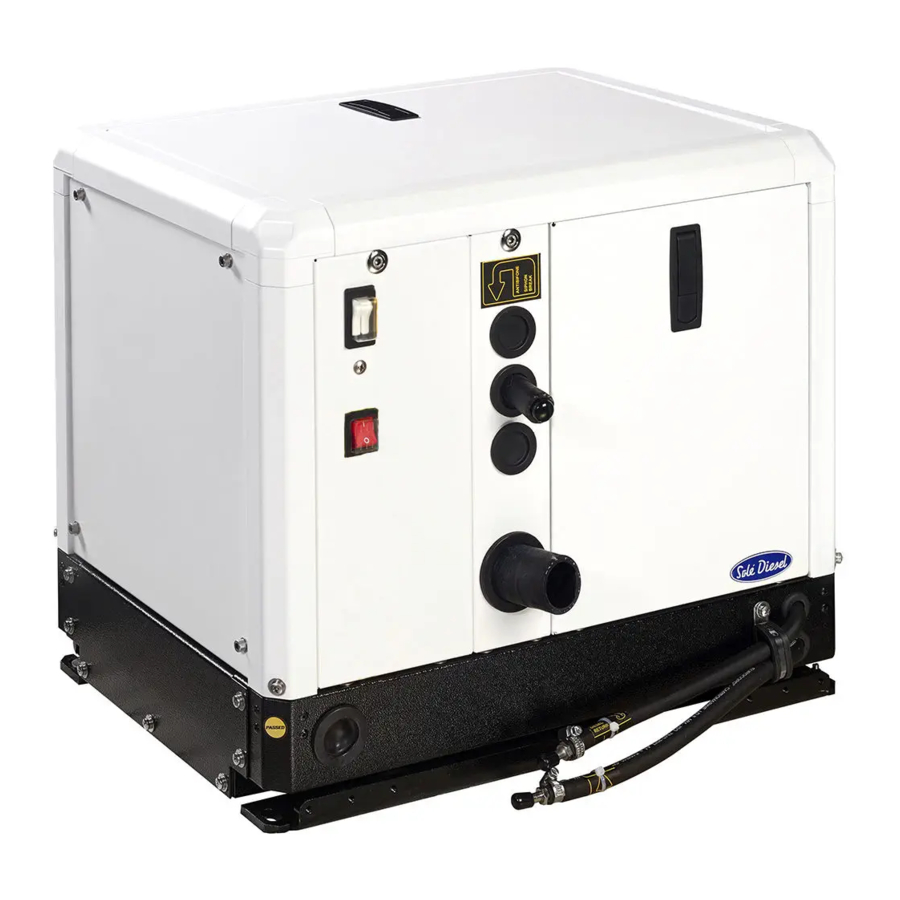
So there is not the need to waste a large room in your boat, and even if the chosen place is away from the center line of the boat, the reduced weight of the 4 GSCH will not influence the stability. NOTICE The images, text and information contained in this manual are based on the product’s features at the time... -
Page 3: Table Of Contents
TABLE OF CONTENTS Introduction ..........................2 Safety Precautions and Instructions....................7 Service Assistance ........................11 Section 1. Genset Information ....................12 1.1. Genset Identification ....................12 1.2. Technical Specifications ....................13 1.3. Genset Limited Warranty .................... 14 Restrictions .......................... 14 After-sales service contact .................... - Page 4 Section 5. Systems and Scheduled Maintenance ................ 31 Operating Description ....................31 Periodic Maintenance Schedule .................. 33 5.3. Lubrication System ...................... 35 5.4. Exhaust System ......................35 5.4. Cooling System ......................... 37 5.5. Fuel System ........................39 5.6. Electrical System ......................40 Troubleshooting ..........................
- Page 5 Fig. 5. Caution label. Overcrank consequences ..................10 Fig. 6. Caution label. Not a step ........................10 Fig. 7. Packed genset ..........................16 Fig. 8. 4 GSCH lifting eyebolt ........................17 Fig. 9. Engine handle ........................... 18 Fig. 10. Free space ............................19 Fig.
- Page 6 LIST OF TABLES Table 1. Technical Specifications 4 GSCH ....................13 Table 2. Limited warranty coverage periods ....................14 Table 3. Angular Operation ........................18 Table 5. Periodic maintenance schedule ....................34 Table 6. Troubleshooting ..........................43...
-
Page 7: Safety Precautions And Instructions
Safety Precautions and Instructions Solé Diesel is concerned for your safety and your machine’s condition. Safety Precautions and Instructions are one of the primary ways to call your attention to the potential hazards associated with our genset operation. Follow the precautions listed throughout the manual before and during operation and maintenance procedures for your safety, the safety of others and the performance of your genset. -
Page 8: Fig. 1. Warning Label. General Precautions
Fig. 1. Warning label. General precautions There are some aspects that you must consider: Obligations: Operator Manual of genset. Read and understand it before operating and servicing the genset to ensure that you follow safe operating practices and maintenance procedures. Grounding electrical equipment. -
Page 9: Fig. 2. Warning. Carbon Monoxide
(3) Disconnect the battery cables. Remove the negative (-) lead first when disconnecting the battery. Reconnect the negative (-) lead last when reconnecting the battery. Follow these precautions to prevent the starting of the genset by genset controller, remote start/stop switch, or engine start command from a remote computer. OTHER WARNINGS (NO ADHESIVE LABEL): Carbon monoxide (CO) can cause severe nausea, fainting or death. -
Page 10: Fig. 5. Caution Label. Overcrank Consequences
CAUTION If the genset does not start after 3 crank attempts an overcrank fault occurs: 1) Close the seacock 2) Drain the water from the exhaust system at the waterlock completely 3) Do not try to restart genset until the cause of start fail is identified Fig. -
Page 11: Service Assistance
Service Assistance For an updated list of our international distribution network, visit Dealers section in our web page www.solediesel.com. Or request this information by contacting Solé Diesel at: e-mail: info@solediesel.com Phone: +34 93 775 14 00 Rev. β... -
Page 12: Section 1. Genset Information
1.1. Genset Identification MANUFACTURER: GENSET MODEL: SOLÉ, S.A. Road from Martorell to Gelida, km 2 4 GSCH (3000 rpm) 08760 MARTORELL (BARCELONA) SPAIN Genset has a little nameplate located on the canopy and another more descriptive on the main alternator... -
Page 13: Technical Specifications
Information Remote control oil pressure and over temperature, -Panel Solé Diesel - SPA 10- starting motor serf disengagement, 10m cable and socket Noise level at 7m (dB(A)) Weight (kg) Table 1. Technical Specifications 4 GSCH Rev. β... -
Page 14: Genset Limited Warranty
1.3. Genset Limited Warranty The genset is designed and built as a power unit for generating electrical energy: ALL USES OTHER THAN THE PRESCRIBED APPLICATION AUTOMATICALLY RELEASE SOLÉ S.A. FROM LIABILITY FOR DAMAGES THAT MAY ENSUE. In any event, the use of products other than those agreed upon at the time of purchase RELEASES SOLÉ... -
Page 15: After-Sales Service Contact
b) The warranty covers the labour costs necessary to replace and/or repair the defective original components, according to Solé Diesel standards of excellence. The time period covered for these operations is limited to 4 hours. c) The warranty covers reasonable costs of travel required to carry out the necessary operations. -
Page 16: Section 2. Transport, Handling And Storage
Section 2. Transport, Handling and Storage 2.1. Receipt When the genset is delivered make sure that the packing has not been damaged during transport and that it has not been tampered with or that components inside the packing have been removed (see information marked on covers, bases and cartons). -
Page 17: Transporting And Handling The Unpacked Genset
When the genset is unpacked and ready for transport, use EXCLUSIVELY the appropriate lifting eyebolts. Fig. 8. 4 GSCH lifting eyebolt 2.4. Storage of Packed and Unpacked Genset If the genset is left idle for prolonged periods, the client must check the possible conditions of conservation in relation to the place of storage. -
Page 18: Section 3. Installation
Section 3. Installation 3.1 Angular Operation Make sure the engine is installed on a level surface. Otherwise, the following angular operation maximum is permitted: Lengthwise Crosswise Maximal Angle 15º 15º Table 3. Angular Operation 3.2 Genset Installation Must be kept enough room around the unit for the following operations: 3.2.1. -
Page 19: For A Correct Air Replacement
3.2.2. For a correct air replacement Around the 4GSCH have at least the shown tolerance; of course the ambient have to be naturally vented with more than one external connection. Fig. 10. Free space 3.2.3. For fixing the Genset on board A solid, level mounting platform is very important for the proper operation of your generator. -
Page 20: Fig. 12. Genset Views
Fig. 12. Genset views Fig. 13. Genset mounts If the vibration-dampening mounts furnished with the generator are not adequate to muffle vibration or resonance in an installation where the mounting surface is not ideal, then adding a plate between the generator and the boat's mounting platform is a possible solution. This will also improve the sound insulation. -
Page 21: External Connections
Fig. 14. Genset top view Fig. 15.Genset base plate 3.2.4. External connections Fig. 16. External connections Rev. β... -
Page 22: Prestart Checklist
The internal diameter of the pipes has to be respected to avoid untightening and leakage, but the external diameter is important too, because the correct size avoids a noise way- out from the sound-proof capsule. 3.2.5. Prestart Checklist Follow these checks and inspections to ensure the correct genset operation. In addition, some checks require verification after unit starts. -
Page 23: Panel Solé Diesel - Spa 10
3.2.6. Panel Solé Diesel - SPA 10 It allows start and stop the unit, to verify if there is a cooling or oil pressure failure, (in this case the engine is shut-off automatically) and the power supplied control. NOTICE The load indicator is designed for avoiding to overcharge the unit feeding too many electrical loads;... -
Page 24: Section 4. Operation
Section 4. Operation 4.1. Starting Genset OPEN THE SEACOCK. Before starting the genset, open the seacock to allow cooling water passage. Failure to do so could damage the seawater pump impeller and cause serious engine overheating damage. PUSH THE START BUTTON of the Panel Solé... -
Page 25: Low Battery Electric Starting
Apply a light load to the generator and allow the engine to warm up to operating temperature before applying heavy loads. Some unstable running may occur in a cold engine. This condition should smooth out as the engine warms up and when the generator loads are applied. 4.1.2. -
Page 26: Device To Help The Starting Attempt After Long Time Inactivity
1. Starting position 2. Neutral position 3. Operating position Fig. 23. Automatic Decompression Device 4.1.3. Device to help the starting attempt after long time inactivity If the engine remains long time unemployed, the oil lubricating the liner drops completely into the sump, so becomes more critical to reach a proper compression to start it. -
Page 27: Fig. 25. Manual Starting
2. Insert the crank handle into the crank handle guide (see illustration). Starting to the right hand on top of the control box and grip the crank handle with your left hand, with the thumb on your left hand in the position shown in the illustration. -
Page 28: Stopping Genset
COOLING SYSTEM: Check the cooling water is flowing properly from the exhaust outlet, outboard When everything is in order, close carefully the capsule and your 4 GSCH is ready for supply trouble less energy. 4.2. Stopping Genset UNLOAD THE GENSET. -
Page 29: Genset Operation At Low Temperatures
4.3. Genset Operation at Low Temperatures Whenever the atmospheric temperature drops below zero, the following series of circumstances occur: The cooling liquid (sea water in cooling system) may freeze. The oil becomes thicker. There is a drop in the voltage at the battery terminals. ... -
Page 30: Winterization And Preservation
4.4. Winterization and Preservation If the boat is not going to be used for a long period of time or during the winter, certain tasks must be carried out to keep it in perfect operating condition. Follow the steps indicated below carefully: 1. -
Page 31: Section 5. Systems And Scheduled Maintenance
Section 5. Systems and Scheduled Maintenance 5.1 Operating Description In order to carry out the scheduled maintenance it is necessary to remove some covers. For this reason, not all covers are shown in the following figures. Information of special tools required and basic safety precautions. Disassembly: ... -
Page 32: Fig. 28. 4 Gsch Parts
Fig. 28. 4 GSCH parts Fig. 29. 4 GSCH parts... -
Page 33: Periodic Maintenance Schedule
5.2 Periodic Maintenance Schedule The maintenance and fault diagnostic procedures involve risks that may cause severe injury or even death. These procedures should therefore be carried out solely by qualified electrical and mechanical specialists. Before any maintenance and cleaning work, make sure that there are no moving parts, that the generator housing has cooled to ambient temperature, that the electricity generating set cannot be accidentally started up and that all procedures are strictly observe Rev. -
Page 34: Table 5. Periodic Maintenance Schedule
Intervals 1st 20h- Every Every Every Every Every 2 Inspection Item Daily Winter storage and Preservation 200h 400h 800h year years Screw tightening, fastening. Engine block. General Valve clearance. Exhaust gas, noise and vibrations. Compression pressure. Genset oil. Lubrication System* Oil filter. -
Page 35: Lubrication System
5.3. Lubrication System Oil forced-feed lubrication system with gear pump with no oil filter. OIL SPECIFICATIONS Use oil with 15W40 viscosity (this is an all-season oil for temperatures ranging between -15ºC and +40ºC) or select the most suitable oil viscosity for the atmospheric temperatures on which the genset is going to be operated. -
Page 36: Fig. 31. Exhaust System 1
Fig. 31. Exhaust System 1 IMPROVED SYSTEM: a further improvement in the noise dampening is achieved fitting instead of the third muffler the water separator. The cooling water is separately thrown from a separate hole flowing smoothly, avoiding the noise produced by the water coming alternatively spread from the exhaust pipe. -
Page 37: Cooling System
5.4. Cooling System Fig. 33. Cooling System NOTICE The unit can be installed below the sea level; in that case the safety cooling vacuum valve has to be fitted on a wall at generator side at least 50 cm above the external sea water line. On the hoods are foreseen two additional holes to be employed for the siphon break pipes. -
Page 38: Fig. 34. Cooling Intake
Fig. 34. Cooling intake Heat recovery system (on request) For heating the boat or producing warm water, using the waste heat of the engine cooling system, a pipe has to be connected according to the drawing. Fig. 35. Heat Recovery System The fiberglass capsule has not the two holes for the pipes, so it has to be drilled out according to board plant. -
Page 39: Fuel System
Fig. 36. Fuel System NOTICE The injection pump of the 4 GSCH is self-bleeding, it means that in case the engine shutoff for lack of fuel, after fuel tank filling up there is no need of disconnecting the pipes for bleeding, because this operation is simply obtained acting by hand on the lever of the feeding pump. -
Page 40: Electrical System
5.6. Electrical System The 4GSCH is negative grounded, and can be connected to the main board batteries 12 V or to a separate small battery 12 V of about 60 Ah; in this second case its internal charging device takes care of feeding the battery with 8 A. -
Page 41: Fig. 39. Shore/Board Line
Fig. 39. Shore/board line Fig. 40. Main Output Rev. β... -
Page 42: Fig. 41. Electrical Plant
Fig. 41. Electrical Plant... -
Page 43: Troubleshooting
Troubleshooting Each unit is carefully tested in our factory and the performances are verified; even so a readjustment can be sometime necessary according to the following suggestions. GENSET FAILURE PROBABLE CAUSES RECOMMENDED ACTIONS Check rpm and set at the nominal value of Low engine speed 3100 rpm without load (3700 for 60 cycles) Faulty capacitor... -
Page 44: Fig. 42. Troubleshooting
MAIN VOLTAGE (230V AC) MISSING: Fig. 42. Troubleshooting... -
Page 45: Warnings
WARNINGS A great marine sets number of any type and manufacture, after first installation on board are flooded by sea water causing severe damages to the unit with high replacement or repairing costs, improperly laimed in warranty but gently refused, because it always depends from a critical installation, made ompromising some physical rules. -
Page 46: Sea Water Intake Installation
For avoiding the risk, the water intake entrance must be fitted facing the rear position and even so, in critical sailing conditions the internal valve must be closed when the generating set is not in operation. Sea Water Intake Installation Considering the water intake / safety valve / strainer and partially the seawater hose are fitted below the seawater line and inside them remains trapped seawater, must be considered the height between the seawater line and the water pump fitted on the generator that must be no more than 60... -
Page 47: Exhaust Line Installation
Exhaust Line Installation The exhaust line can contain too much water for length excess or negative gradient course that returns back into the engine when the set is shut off. The first water lock muffler is designed for avoiding that risk, but if fitted not enough lower than the engine manifold either reversing the entrance with the outlet, or of too reduced capacity for the return water volume that has to contain, can be unable avoiding the problem. - Page 48 When the installation is correctly planned and carried on, surveying the result during the first operative season, the generator on board give many troubles operative seasons, requiring lubricating oil and fuel filter replacement only, but there is another up keeping operation that prolong considerably the unit life.
- Page 49 U_GQNG_EN Rev. 0 Rev. β...
Need help?
Do you have a question about the 4 GSCH and is the answer not in the manual?
Questions and answers