Sign In
Upload
Manuals
Brands
Sole Diesel Manuals
Portable Generator
8 GSAC
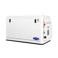
Sole Diesel 8 GSAC Marine Generator Set Manuals
Manuals and User Guides for Sole Diesel 8 GSAC Marine Generator Set. We have
3
Sole Diesel 8 GSAC Marine Generator Set manuals available for free PDF download: Operator's Manual
Sole Diesel 8 GSAC Operator's Manual (120 pages)
Marine generator sets
Brand:
Sole Diesel
| Category:
Portable Generator
| Size: 6 MB
Table of Contents
Table of Contents
4
Introduction
3
Table of Contents
4
Fig. 1. Warning Label. in Case of Fire
8
Safety Precautions and Instructions
8
Fig. 2. Warning Label. General Precautions
9
Fig. 3. Warning Label. Rotating Parts
9
Fig. 4. Warning. Carbon Monoxide
10
Fig. 5. Warning. Battery Charging
10
Fig. 6. Warning. Hot Engine
10
Fig. 7. Caution Label. Overcrank Consequences
10
Fig. 8. Caution Label. Not a Step
11
Service Assistance
12
Section 1 Genset Information
13
Genset Identification
13
Fig. 9. Nameplate Location
13
Fig. 10. Genset Nameplate
13
Technical Specifications
14
Table 1. Technical Specifications 8 GTC / 10 GTAC / 7 GSC / 8 GSAC / 11 GTC / 14 GTAC
15
Diesel Engine
16
Table 2. Technical Specifications 10 GSC / 12 GSAC / 17 GTC / 20 GTAC / 14 GSC / 17 GSAC
17
Genset Limited Warranty
18
Restrictions
18
Table 3. Limited Warranty Coverage Periods
18
After-Sales Service Contact
19
Section 2 Transport, Handling and Storage
20
Receipt
20
Transporting and Handling the Packed Genset
20
Fig. 11. Packed Genset
20
Transporting and Handling the Unpacked Genset
21
Fig. 12. 8 GTC / 10 GTAC / 7 GSC / 8 GSAC Lifting Eyebolts
21
Fig. 13. 11 GTC / 14 GTAC / 10 GSC / 12 GSAC / 17 GTC / 20 GTAC / 14 GSC / 17 GSAC Lifting
21
Storage of Packed and Unpacked Genset
22
Section 3 Installation
23
Angular Operation
23
Genset Installation
23
Table 4. Angular Operation
23
Prestart Checklist
24
Fig. 14. Genset Controller
25
Genset Operation at Low Temperatures
26
Winterization and Preservation
26
Restoration of Operational Conditions
27
Section 4 Operation
25
Starting Genset
25
Stopping Genset
25
Fig. 15. Genset Covers
28
Section 5 Systems and Scheduled Maintenance
28
Operating Description
28
Fig. 16. Location of Genset Elements 8 GTC / 10 GTAC / 7 GSC / 8 GSAC
29
Fig. 17. Location of Genset Elements 11 GTC / 14 GTAC / 10 GSC / 12 GSAC / 17 GTC / 20 GTAC / 14 GSC / 17 GSAC
30
Periodic Maintenance Schedule
31
General
32
Table 5. Periodic Maintenance Schedule
32
Maintenance Task. Screw Tightening, Fastening
33
Maintenance Task. Valve Clearance Inspection
33
Table 6. Valve Clearance
33
Table 7. Injection Sequence
33
Maintenance Task. Compression Pressure Inspection
34
Fig. 18. Maintenance Kit
33
Fig. 19. Valve Clearance Inspection
34
Fig. 20. Valve Clearance Adjust
34
Fig. 21. Compression Pressure Inspection
34
Lubrication System
35
Circuit Description
35
Table 8. Compression Pressure Inspection
35
Oil Specifications
36
Maintenance Task. Oil Level Check
36
Fig. 22. Lubrication Circuit
35
Table 9. Oil Circuit Capacity
36
Table 10. Modification of Oil Dipstick for Inclined Operation 8 GTC / 10 GTAC / 7 GSC / 8 GSAC
36
Maintenance Task. Oil Fill / Change
37
Fig. 24. Solé Diesel Oil SAE 15W40
36
Table 11. Modification of Oil Dipstick for Inclined Operation
37
Maintenance Task. Oil Filter Change
38
Fuel System
38
Circuit Description
38
Fuel Specifications
38
Fig. 25. Modification of Oil Dipstick for Inclined Operation
37
Fig. 26. Oil Filter Change
38
Fig. 27. Fuel Circuit
38
Maintenance Task. Fuel Level Inspection
39
Maintenance Task. Fuel Tank Clean
39
Maintenance Task. Fuel Filter Change
39
Maintenance Task. Water Separator Filter Purgue
39
Maintenance Task. Injection Pump Inspection
39
Fig. 28. Fuel Filter Change
39
Fig. 29. Water Separator Filter Change
39
Maintenance Task. Injector Inspection
40
Table 12. Injection Pressure
40
Maintenance Task. Bleeding Air from the Fuel System
41
Fig. 29. Remove Injector
40
Fig. 31. Test Injection Pressure
40
Fig. 32. Adjust Injection Pressure
40
Fig. 33. Shape of Injector Discharge
40
Fig. 34. Tip and Nozzle of Injector
41
Cooling System
42
Coolant Circuit Description
42
Seawater Circuit Description
42
Coolant Specifications
42
Table 13. Coolant Circuit Capacity
42
Maintenance Task. Coolant Check
43
Maintenance Task. Coolant Fill / Change
43
Fig. 36. Coolant Circuit
42
Fig. 37. Seawater Circuit
42
Fig. 38. Coolant Drain Plugs
43
Fig. 39. Refill Coolant Circuit
43
Maintenance Task. Seawater Filter Inspection
44
Maintenance Task. Seawater Pump Impeller Inspection
44
Fig. 40. Seawater Filter
44
Fig. 41. Seawater Pump Impeller Inspection
44
Inlet and Exhaust System
45
Exhaust Circuit Description
45
Table 14. Minimum Exhaust Muffler Capacity
45
Maintenance Task. Air Filter Inspection
46
Maintenance Task. Exhaust Gas, Noise and Vibrations Inspection
46
Fig. 45. Air Filter Inspection
46
Electrical System
47
SCO 10 Panel
47
Table 15. References of Genset Controller
47
Battery
48
Circuit Protection
48
Maintenance Task. Incandescent Glow Plug Inspection
48
Fig. 46. Genset Panel
47
Table 17. Recommended Battery Capacity
48
Table 17. AC Breaker
48
Maintenance Task. Starter Motor Inspection
49
Maintenance Task. Alternator Belt Tension Inspection
49
Fig. 47. Incandescent Glow Plug Inspection
48
Table 18. Alternator Belt Tension Inspection
49
Maintenance Task. Battery Level
50
Alternator
50
Maintenance Task. Control of Windings and Electrical Insulation
50
Maintenance Task. Control of Bearings
50
Table 19. Operating Hours to Alternator Bearing Replace
50
Maintenance Task. Cleaning and Lubrication
51
Fig. 48. Glow Plug Behavior
49
Fig. 49. Starter Motor Inspection
49
Fig. 50. Alternator Belt Tension Inspection
49
Section 6 Troubleshooting
51
Table 20. Toubleshooting
56
Table of Contents
59
1 Introduction to the SCO
60
Remote Control
60
Safety Instructions
60
2 General Description
61
Technical Data
61
Power Supply
61
Operating Conditions
61
Dimensions and Weight
61
3 Installation
62
Remote SCO
63
Isolation Transformers (IG-MTU Unit)
64
4 Operator Interface SCO
65
Display Screens and Pages Structure
67
Measurement
67
Setpoint. Controller Information Screen
68
Setpoint. Maintenance Hours Change
69
Setpoint. Entering the Password
70
History Log
71
Alarm List
72
Display Contrast Adjustment
72
Change Language
73
5 Alarm Management
74
Sensor Fail (FLS)
74
Warning (WRN)
74
Shut down (SD)
74
Voltage Phase Sequence Detection
74
6 Setpoints
75
Basic Settings
75
Engine Protections
75
Extension I/O
75
Date/Time
76
SMS/E-Mail
77
7 Function Description
78
8 Genset Operation States
78
9 Maintenance
82
10 Connection Description
83
11 Sensors and Switches Specifications
84
Advertisement
Sole Diesel 8 GSAC Operator's Manual (82 pages)
Marine generator sets
Brand:
Sole Diesel
| Category:
Portable Generator
| Size: 3 MB
Table of Contents
Introduction
3
Table of Contents
4
Table of Contents
6
Safety Precautions and Instructions
7
Solé, S.A. C-243 B, Km 2 · 08760 Martorell (Barcelona) ·Tel. +34 93 775 14 00 · Www.solediesel.com · Info@Solediesel.com
8
Engine Labels
9
Solé Diesel Warranty
10
Solé Diesel Limited Warranty
10
Solé Diesel Extended Warranty
10
Restrictions
10
Responsibilities
11
After-Sales Service Contact
12
Section 1 - Genset Information
13
Genset Identification
13
Genset Parts Identification
14
Section 2 - Transport, Handling and Storage
16
Reception
16
Transporting and Handling the Packed Genset
16
Transporting and Handling the Unpacked Genset
17
Storage of Packed and Unpacked Genset
17
Section 3 - Installation
18
Angle of Installation
18
Genset Installation
18
Section 4 - Operation
19
Prestart Checklist
19
Genset Operation at Low Temperatures
19
Winterzation and Preservation
20
Maintenance During the Storage
21
Restoration of Operational Conditions
21
Section 5 - Systems and Scheduled Maintenance
22
Operating Description
22
Periodic Maintenance Schedule
22
General
24
Maintenance Task. Screw Tightening, Fasteningt
24
Maintenance Task. Valve Clearance Inspection
24
Maintenance Task. Compression Pressure Inspection
25
Lubrication System
26
Circuit Description
26
Oil Specifications
26
Maintenance Task. Oil Filter Change
26
Maintenance Task. Oil Level Check
27
Maintenance Task. Oil Fill / Change
27
Circuit Description
28
Fuel Specifications
28
Maintenance Task. Fuel Level Inspection
28
Maintenance Task. Fuel Tank Clean
28
Maintenance Task. Water Separator Filter Purge
28
Maintenance Task. Fuel Filter Change
29
Maintenance Task. Injection Pump Inspection
29
Maintenance Task. Injector Inspection
29
Maintenance Task. Bleeding Air from the Fuel System
30
Cooling System
31
Coolant Specifications
31
Maintenance Task. Coolant Check
31
Maintenance Task. Coolant Fill / Change
32
Maintenance Task. Seawater Filter Inspection
32
Maintenance Task. Seawater Pump Impeller Inspection
32
Inlet and Exhaust System
33
Exhaust Circuit Description
33
Maintenance Task. Air Filter Inspection
34
Maintenance Task. Exhaust Gas, Noise and Vibrations Inspection
34
Electrical System
35
SCO 10 Panel
35
Battery
35
Circuit Protection
36
Maintenance Task. Incandescent Glow Plug Inspection
36
Maintenance Task. Starter Motor Inspection
36
Maintenance Task. Alternator Belt Tension Inspection
36
Maintenance Task. Battery Level
37
Alternator
37
Maintenance Task. Control of Windings and Electrical Insulation
37
Maintenance Task. Control of Bearings
37
Maintenance Task. Cleaning and Lubrication
38
Section 6 - SCO 10 PANEL
39
Installation
39
Operator Interface SCO 10
40
Genset Operator Indicators
41
Displays and Control Button
41
Display Screens and Pages Structure
41
Measurement
42
Setpoint. Controller Information Screen
44
Set Point. Maintenance Hours Change
45
History Log
46
Alarm List
47
Display Contrast Adjustment
47
Change Language
48
Alarm Management
49
Section 7 - Troubleshooting
50
Section 8 - Technical Specifications
56
Section 9 - Tightening Torques
60
Section 10 - Technical Appendices
61
Wiring Diagrams
62
Alternator Connections
67
Regulator Connections
70
Overall Dimensions
72
Section 11 - Instructions to Replace and Remove
76
Section 12 - Inspection Prior to the Delivery of Propulsion Engines
77
Maintenance Log
79
Sole Diesel 8 GSAC Operator's Manual (94 pages)
Marine generator sets
Brand:
Sole Diesel
| Category:
Portable Generator
| Size: 6 MB
Table of Contents
Introduction
3
Table of Contents
4
Safety Precautions and Instructions
7
Solé Diesel Warranty
10
Section 1 - Genset Information
13
Genset Identification
13
Genset Parts Identification
14
Section 2 - Transport, Handling and Storage
17
Reception
17
Transporting and Handling the Packed Genset
17
Transporting and Handling the Unpacked Genset
18
Storage of Packed and Unpacked Genset
18
Section 3 - Installation
19
Angle of Installation
19
Genset Installation
19
Section 4 - Operation
20
Prestart Checklist
20
Genset Operation at Low Temperatures
20
Winterzation and Preservation
21
Maintenance During the Storage
22
Restoration of Operational Conditions
22
Section 5 - Systems and Scheduled Maintenance
23
Operating Description
23
Periodic Maintenance Schedule
23
General
25
Maintenance Task. Screw Tightening, Fastening
25
Maintenance Task. Valve Clearance Inspection
25
Maintenance Task. Compression Pressure Inspection
26
Lubrication System
27
Circuit Description
27
Oil Specifications
27
Maintenance Task. Oil Filter Change
27
Maintenance Task. Oil Level Check
28
Maintenance Task. Oil Fill / Change
28
Fuel System
29
Circuit Description
29
Fuel Specifications
29
Maintenance Task. Fuel Level Inspection
29
Maintenance Task. Fuel Tank Clean
29
Maintenance Task. Water Separator Filter Purge
29
Maintenance Task. Fuel Filter Change
30
Maintenance Task. Injection Pump Inspection
30
Maintenance Task. Injector Inspection
30
Maintenance Task. Bleeding Air from the Fuel System
31
Cooling System
32
Coolant Specifications
32
Maintenance Task. Coolant Check
32
Maintenance Task. Coolant Fill / Change
33
Maintenance Task. Seawater Filter Inspection
33
Maintenance Task. Seawater Pump Impeller Inspection
33
Maintenance Task. Zinc Anode Inspection
34
Inlet and Exhaust System
34
Exhaust Circuit Description
34
Maintenance Task. Air Filter Inspection
35
Maintenance Task. Exhaust Gas, Noise and Vibrations Inspection
36
Electrical System
36
Panel
36
Sensors and Switches
36
Battery
38
Circuit Protection
38
Maintenance Task. Incandescent Glow Plug Inspection
38
Maintenance Task. Starter Motor Inspection
39
Maintenance Task. Alternator Belt Tension Inspection
39
Maintenance Task. Battery Level
39
Alternator
39
Maintenance Task. Control of Windings and Electrical Insulation
39
Maintenance Task. Control of Bearings
40
Maintenance Task. Cleaning and Lubrication
40
Section 6 - Troubleshooting
41
Section 7 - Technical Specifications
47
Section 8 - Tightening Torques
64
Section 9 - Technical Appendices
65
9.1. Wiring Diagrams
65
9.2. Alternator Connections
74
Connection's Type 1
74
Connection Type 2
75
Connection Type 3
76
9.3. Regulator Connections
77
Connection Type 1
77
Connection Type 2
77
Connection Type 3
78
9.4. Overall Dimensions
79
Section 10 - Instructions to Replace and Remove
88
Section 11 - Inspection Prior to the Delivery of Generator Sets
89
Section 12 - Maintenance Log
91
Advertisement
Advertisement
Related Products
Sole Diesel 8 GTC
Sole Diesel 84 GTAC
Sole Diesel 84 GTA
Sole Diesel 85 GTC
Sole Diesel 85 GT
Sole Diesel 8 GSA/GSAC
Sole Diesel 8 GT/GTC
Sole Diesel 8 GSA
Sole Diesel 8 GT
Sole Diesel 84 GTA/GTAC
Sole Diesel Categories
Engine
Portable Generator
Control Panel
Inverter
More Sole Diesel Manuals
Login
Sign In
OR
Sign in with Facebook
Sign in with Google
Upload manual
Upload from disk
Upload from URL