
Related Manuals for DFI ST102-SD


Summary of Contents for DFI ST102-SD
- Page 1 ST102-SD Desktop Box PC User’s Manual Preliminary Version A52801917 Chapter 1 Introduction www.dfi.com...
-
Page 2: Copyright
Product names or trademarks appearing in this manual are for identification purpose only and ance could void the user’s authority to operate the equipment. are the properties of the respective owners. Shielded interface cables must be used in order to comply with the emission limits. Chapter 1 Introduction www.dfi.com... -
Page 3: Table Of Contents
UEFI Device Manager................. 35 Key Features .......................... 6 Security ................... 39 Specifications ........................7 Boot ............................40 Getting to Know the ST102-SD ..................8 Exit ....................41 Updating the BIOS ......................41 Mechanical Dimensions ....................9 Notice: BIOS SPI ROM ......................42 Motherboard Dimensions .................... -
Page 4: About This Manual
About this Manual Static Electricity Precautions An electronic file of this manual can be obtained from the DFI website at www.dfi.com. To It is quite easy to inadvertently damage your PC, system board, components or devices even download the user’s manual from our website, please go to Support > Download Center. On before installing them in your system unit. -
Page 5: Safety Precautions
• Unplug the power cord before removing the system chassis cover for installation or servic- ing. After installation or servicing, cover the system chassis before plugging the power cord. • 1 ST102-SD system unit • 1 HDD drive bay kit •... -
Page 6: Chapter 1 - Introduction
Chapter 1 Chapter 1 - Introduction Key Features Overview Model Name ST102-SD 6th/7th Generation Intel ® Core i7/i5/i3 processors Processor 2 LAN ports 1 DP/HDMI (DP available upon request), 1 DVI-D (DVI-I connector) Displays 2 USB 2.0 ports (front) 4 USB 3.0 ports (rear) -
Page 7: Specifications
Other Features • Watchdog Timer function; System Reset, programmable via software from 1 to - DC-in External Power Adapter: DC output 12V 100W, Level 6 255 Seconds Cooling System 1 x System Fan 1 x CPU Fan Chapter 1 Introduction www.dfi.com... -
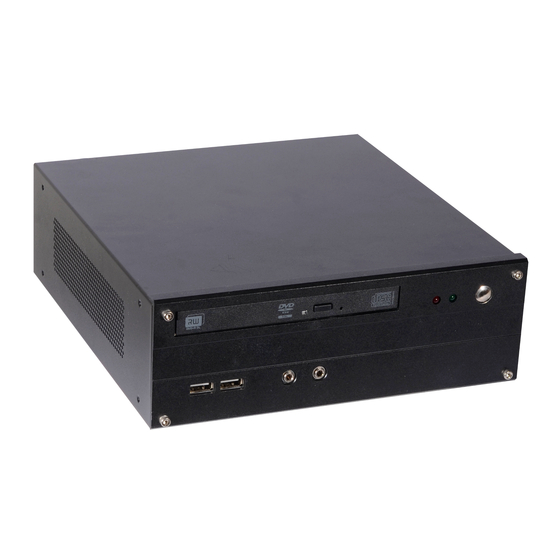
Page 8: Getting To Know The St102-Sd
Chapter 1 Getting to Know the ST102-SD Front View Rear View Power Button DVD Drive DC-in DVI-D USB 3.0 LAN Ports Line-out USB 2.0 HDD LED Mic-in USB 2.0 Power LED DVD RW Drive DC-in Jack A Slim Optical Disc Drive (ODD) for reading a disc. -
Page 9: Mechanical Dimensions
Chapter 1 Mechanical Dimensions Motherboard Dimensions Rear View 0.00 33.02 62.48 8.50 Right View 133.42 Left View 137.49 165.10 165.10 170.00 Front View Chapter 1 Introduction www.dfi.com... -
Page 10: Chapter 2 - Getting Started
Installing the Drivers The system package includes a CD disk. The CD includes drivers that must be installed to pro- vide the best system performance. Refer to the Supported Software chapter for instructions on installing the drivers. Chapter 2 Getting Started www.dfi.com... -
Page 11: Chapter 3 - Installing Devices
Remove these screws and then put them in a safe place for later use. Mounting screw The SODIMM sockets and SATA drive bay are readily accessible after removing the chassis cover. SATA drive bay ODD drive bay Chapter 3 Installing Devices www.dfi.com... - Page 12 Mounting screw HDD bracket Mounting screw Align the mounting holes on the SATA drive with the mounting holes on the HDD bracket. SATA mounting screws SATA mounting screws HDD bracket Mounting screw Mounting screw Chapter 3 Installing Devices www.dfi.com...
-
Page 13: Installing A Memory Module
If installing only one memory module, please install it on the memory socket labeled DIMM 1 (the one closer to the center of the board). The SODIMM sockets can only accommodate DDR4 memory modules. Please do not install other types of memory modules. Chapter 3 Installing Devices www.dfi.com... -
Page 14: Chapter 4 - Jumper Settings
3. Now plug the power cord and power-on the system. Important: Before powering on the system, make sure that the power settings of JP6 match the power specification of backlight control. Selecting the incorrect voltage will seriously damage the backlight. Chapter 2 Hardware Installation www.dfi.com Chapter 4 Jumper Settings... -
Page 15: Panel Power Select
5 seconds (power flicker). Important: Before powering-on the system, make sure that the power settings of JP8 match the LCD panel’s specification. Selecting the incorrect voltage will seriously damage the LCD panel. Chapter 2 Hardware Installation www.dfi.com Chapter 4 Jumper Settings... -
Page 16: Com 1 Rs232/Power Select
The pin functions of COM 1 will vary according to JP2’s setting respectively. JP7 is used to select the power level of LVDS LCD/inverter power connector. 3-5 (+5V), 4-6 (+12V) On: 1-3 (RI), 2-4 (DCD) On: RS232 (default) RS232 with power COM 1 Chapter 2 Hardware Installation www.dfi.com Chapter 4 Jumper Settings... -
Page 17: Chapter 5 - Ports And Connectors
Note: Angled-corner Align this edge with the Aligning side Angled-corner Please gently press the power button to avoid possible damage. left side of the connector (left) (up) Chapter 5 Ports and Connectors www.dfi.com... -
Page 18: Rj45 Lan Ports
Configure the onboard LAN ports in the Advanced menu (“ACPI Configuration” submenu) of the BIOS. Refer to Chapter 7 - BIOS for more information. Driver Installation Install the LAN drivers. Refer to Chapter 8 - Supported Software for more information. Chapter 5 Ports and Connectors www.dfi.com... -
Page 19: Graphics Interfaces
Connect the display device’s cable connector to the DVI-I port. After plugging the cable con- nector into the port, gently tighten the cable screws to hold the connector in place. Driver Installation Install the graphics driver. Refer to Chapter 8 - Supported Software for more information. Chapter 5 Ports and Connectors www.dfi.com... -
Page 20: Dc-In Jack
Configure the audio settings in the Advanced menu (“Audio Configuration” submenu) of the BIOS. Refer to Chapter 7 - BIOS for more information. Driver Installation Install the audio driver. Refer to Chapter 8 - Supported Software for more information. Chapter 5 Ports and Connectors www.dfi.com... -
Page 21: I/O Connectors
ATA data cable to a SATA connector and the other end to your Serial ATA device. DIO5 DIO4 BIOS Setting DIO3 Configure the Serial ATA drives in the Advanced menu (“SATA Configuration” submenu) of the DIO2 BIOS. Refer to Chapter 7 - BIOS for more information. DIO1 DIO0 Chapter 5 Ports and Connectors www.dfi.com... -
Page 22: Cooling Fan Connectors
It can expand the system’s storage capacity. PCI Express x4 Slot Install PCI Express cards such as network cards or USB expansion cards that comply to the PCI Express specifications into the PCI Express x4 slot. Chapter 5 Ports and Connectors www.dfi.com... -
Page 23: Chassis Intrusion Connector
To RAM) state, it will blink every 4 seconds. Pin Pin Assignment Pin Pin Assignment HDD Power LED Power HDD LED Signal PWR LED LED Power Ground Signal RST Signal Ground RESET SW ATX SW N.C. Signal Chapter 5 Ports and Connectors www.dfi.com... -
Page 24: Smbus Connector
It is a multiple device bus that allows multiple chips to connect to the same bus and digital audio transmission or output. enable each one to act as a master by initiating data transfer. Chapter 5 Ports and Connectors www.dfi.com... -
Page 25: Battery
Failure to do so will cause severe damage to the motherboard and components. Safety Measures • Danger of explosion if battery incorrectly replaced. • Replace only with the same or equivalent type recommend by the manufacturer. • Dispose of used batteries according to local ordinance Chapter 5 Ports and Connectors www.dfi.com... -
Page 26: Com (Serial) Ports
Make sure the colored stripe on the ribbon cable is aligned with pin 1 of the COM connector. BIOS Setting Configure the serial COM ports including the communication mode in the Advanced menu (“SIO NUVOTON6106D” submenu) of the BIOS. Refer to Chapter 7 for more information. Chapter 5 Ports and Connectors www.dfi.com... -
Page 27: Lvds Lcd Panel Connector
Configure the LCD panel in the Advanced menu (“Video Configuration” sub- Panel Power Panel Power menu) of the BIOS. Refer to Chapter 7 for more information. Panel Power Panel Power Note: DFI board's LVDS connector: Hirose DF13-40DP-1.25V(91)/40P/1.25mm; cable side connector: Hirose DF13-40DS-1.25C. Chapter 5 Ports and Connectors www.dfi.com... - Page 28 The mounting holes are located at the side panel of the system. Fasten the mounting stand on the side of the system using the mounting screws. Mounting screws Place the system upright with the stand's support at the bottom. Desktop mounting stand Chapter 6 Mounting Options www.dfi.com...
-
Page 29: Chapter 7 - Bios Setup
“Press DEL to run setup” will appear on the screen. If the message that field and press <Enter>. disappears before you respond, restart the system or press the “Reset” button. You may also restart the system by pressing the <Ctrl> <Alt> and <Del> keys simultaneously. www.dfi.com Chapter 7 BIOS Setup... -
Page 30: Insyde Bios Setup Utility
The time format is <hour>, <minute>, <second>. The time is based on the 24-hour military-time clock. For example, 1 p.m. is 13:00:00. Hour displays hours from 00 to 23. Minute displays minutes from 00 to 59. Second displays seconds from 00 to 59. www.dfi.com Chapter 7 BIOS Setup... - Page 31 Please check the software specifications to determine if enabling HT can be advantageous to the overall system performance. Note this function is not available with the Intel ® Core™ i5-6500TE, Pentium G4400TE and Celeron G3900TE processors. ® ® www.dfi.com Chapter 7 BIOS Setup...
- Page 32 PEG: PEG (PCIe Graphics devices connected to PEG lanes) -> PCIe graphics devices -> PCI graphics devices -> IGFX (internal graphics) PCI: PCI graphics devices -> PCIe graphics devices -> PEG (PCIe Graphics de- vices connected to PEG lanes ) -> IGFX (internal graphics) www.dfi.com Chapter 7 BIOS Setup...
- Page 33 This option allows the Serial ATA devices to use AHCI (Advanced Host Controller Interface). Serial ATA Port 0, 1, 2, and 3 and Hot Plug Enable or disable the serial ATA port and its hot plug function. www.dfi.com Chapter 7 BIOS Setup...
- Page 34 Enabled / Disabled Enable or disable this PCIe slot. PCIe Speed Select the PCIe speed: Auto, Gen1 (2.5 GT/s) or Gen2 (5 GT/s). Hot Plug Enable or disable hot plug function of the PCIe root port. www.dfi.com Chapter 7 BIOS Setup...
-
Page 35: Uefi Device Manager
“Legacy” boot mode. Refer to the “Boot” section in this chapter. After this function is selected, the screen will warn you that you are going to exit the BIOS setup utility. Me Fw Image Re-Flash Enable or disable flashing of the Intel Management Engine firmware. ® www.dfi.com Chapter 7 BIOS Setup... - Page 36 Local Gateway: Enter the gateway address in the IPv4 format. This screen shows hardware information for the Ethernet controllers and configures Local DNS (Domain Name System) Servers: Enter DNS (Domain Name System) server IP their operation. addresses in the IPv4 format. www.dfi.com Chapter 7 BIOS Setup...
- Page 37 The range of the temperature is from 0 to 127 Fan Speed Count 1 to Fan Speed Count 4 Set the fan speed. The range is from 1 (lowest speed)-10 (full speed). www.dfi.com Chapter 7 BIOS Setup...
- Page 38 Parity: None, Even or Odd. Stop bits: 1 bit or 2 bits. Flow control: None, RTS/CTS or XON/XOFF This is the global setting for all of the designated serial ports for the console redirec- tion function. www.dfi.com Chapter 7 BIOS Setup...
-
Page 39: Security
1 character and less than or equal to 10 characters. Power-on Password If you select to set the supervisor password, this option will be shown. Enable or dis- able prompt for password at boot. www.dfi.com Chapter 7 BIOS Setup... -
Page 40: Boot
Enable or disable the quiet boot function to configure the screen’s display between list has the highest boot priority. POST messages or the OEM logo at bootup. Select Disabled to display the POST mes- sages and select Enabled to display the OEM logo. www.dfi.com Chapter 7 BIOS Setup... -
Page 41: Exit
For instructions on how to update BIOS with the flash utility, please see https://www.dfi.com/ Knowledge/Video/31 from the Knowledge Base of the DFI website. Read file successfully. (path= “platform.ini”) Information Please do not remove the AC power Insyde H20FFT (Flash Firmware Tool) Version (SEG) 100.00.08.10 Copyright(c) 2012 - 2016, Insyde Software Corp. -
Page 42: Notice: Bios Spi Rom
When the BIOS IC needs to be replaced, you have to populate it properly onto the system board after the EEPROM programmer has been burned and follow the technical person's instructions to confirm that the MAC address should be burned or not. www.dfi.com Chapter 7 BIOS Setup... -
Page 43: Chapter 7 - Supported Software
CD that contain drivers. You can also download the latest drivers from the DFI Download Center: Please use the following procedure to install the “Intel Chipset Device Software”. - Page 44 1 to 2 minutes (while WinSAT is running) before the Windows 7/Windows 8.1/Windows 10 desktop appears. The “blank screen” period is the time Windows is testing the graphics performance. 2. Read the license agreement and then click “Yes”. www.dfi.com Chapter 8 Supported Software...
- Page 45 Restarting the system will allow the new software installation to take effect. 5. Click “Yes, I want to restart this computer now” and then click “Finish”. Restarting the system will allow the new software installation to take effect. www.dfi.com Chapter 8 Supported Software...
- Page 46 “I accept the terms in the license agreement” if you agree the terms in the agree- ment, and then click “Next”. 3. Select the program features you want to install and then click “Next”. www.dfi.com Chapter 8 Supported Software...
- Page 47 “I accept the terms in the license agreement” if you agree with the terms in the agreement, and then click “Next”. 5. After the installation is complete, click “Finish” to exit setup. www.dfi.com Chapter 8 Supported Software...
- Page 48 Click “Next” to begin the installa- tion. 2. Read the license agreement care- fully. Click “I accept the terms in the License Agreement” if you agree with the terms in the agreement and then click “Next”. www.dfi.com Chapter 8 Supported Software...
- Page 49 Chapter 8 5. Setup is now installing the driver. 6. Click “Finish” to exit setup. www.dfi.com Chapter 8 Supported Software...
Need help?
Do you have a question about the ST102-SD and is the answer not in the manual?
Questions and answers