
Related Manuals for DFI EC700-ADN


Summary of Contents for DFI EC700-ADN
- Page 1 EC700-ADN/ EC710-ADN Fanless Embedded System User’s Manual © January 07, 2025 DFI Inc.
-
Page 2: Fcc And Doc Statement On Class A
1. The changes or modifications not expressly approved by the party responsible for com- are the properties of the respective owners. pliance could void the user’s authority to operate the equipment. 2. Shielded interface cables must be used in order to comply with the emission limits. User's Manual | EC700-ADN/ EC710-ADN... -
Page 3: Table Of Contents
Chapter 1 - Introduction........................ 6 IT8786 Super IO Configuration ► Serial Port 3,4 Configuration ......28 IT8786 Hardware Monitor .....................28 Overview - EC700-ADN ......................6 Serial Port Console Redirection ...................29 Front View ........................6 Serial Port Console Redirection ► Console Redirection Settings ......29 Rear View ......................... -
Page 4: About This Manual
It must be returned to the purchase point, factory or authorized service agency for all such work. 4. We will not be liable for any indirect, special, incidental or consequential damages to the product that has been modified or altered. User's Manual | EC700-ADN/ EC710-ADN... -
Page 5: Static Electricity Precautions
Make sure the system is placed or mounted correctly and stably to prevent the chance of dropping or falling may cause damage. • The openings on the system shall not be blocked and shall be kept in distance from User's Manual | EC700-ADN/ EC710-ADN... -
Page 6: Chapter 1 - Introduction
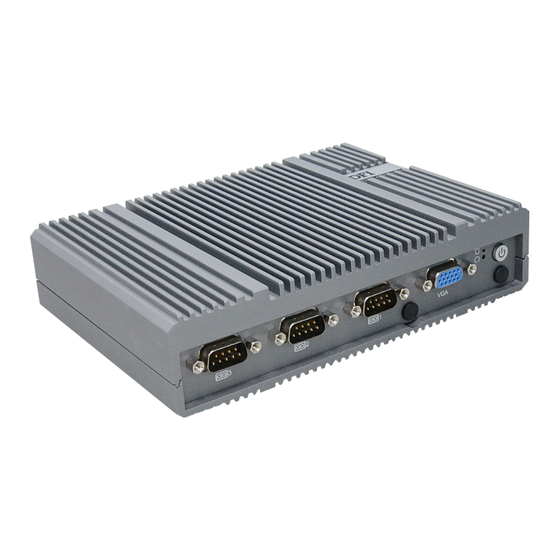
Front View COM3 LAN1/2 ( 2.5G ) COM2 LAN3 COM1 USB-C HDMI ▲Storage LED Line Out / Mic In ▼Reset Button Rear View Power Button COM4 / DIO Antenna Holes Grounding DC In USB3.2 Type A User's Manual | EC700-ADN/ EC710-ADN... -
Page 7: Overview - Ec710-Adn
Front View COM3 LAN1/2 ( 2.5G ) COM2 LAN3 COM1 USB-C HDMI ▲Storage LED Line Out / Mic In ▼Reset Button Rear View Power Button COM4 / DIO Antenna Holes Grounding DC In USB3.2 Type A User's Manual | EC700-ADN/ EC710-ADN... -
Page 8: Dimensions
Supported by X series CPU and TSN standard up to 2.5GbE (Opt.) On Board DDR5 & eMMC Support: LPDDR5 4800 MHz memory down eMMC module –Easy maintenance. Up to Quad Display Support: Support via HDMI/USB-C/VGA, Quad display support by Dev. EC710-ADN User's Manual | EC700-ADN/ EC710-ADN... -
Page 9: Block Diagram
Chapter 1 INTRODUCTION X Block Diagram User's Manual | EC700-ADN/ EC710-ADN... -
Page 10: Specifications
1 x M.2 3042/3052 B key: USB3.0/USB2.0/ 1 x M.2 3042/3052 B key: USB3.0/USB2.0/ PCIe with SIM PCIe with SIM 1 x M.2 2242/2280 M key (*PCIe/SATA) 1 x M.2 2242/2280 M key (*PCIe/SATA) *PCIe:PCIex2 support by project User's Manual | EC700-ADN/ EC710-ADN... - Page 11 1 x Reset Button 1 x Reset Button 2 x 2.5GbE RJ45 2 x 2.5GbE RJ45 Ethernet 1 x GbE RJ45 (support DFI OOB) 1 x GbE RJ45 (support DFI OOB) COM 4: RS232/DIO Serial COM 4: RS232/DIO 3 x USB 3.2 type A 3 x USB 3.2 type A...
- Page 12 Weight Shock 30G, IEC-60068-2-27 MIL-STD-810G 30G, IEC-60068-2-27 MIL-STD-810G (During Operation) STANDARDS AND Vibration 3 Grms, IEC 60068-2-64 MIL-STD-810G 3 Grms, IEC 60068-2-64 MIL-STD-810G CERTIFICATIONS (During Operation) Certifications CE, FCC, RoHS, UKCA CE, FCC, RoHS, UKCA User's Manual | EC700-ADN/ EC710-ADN...
-
Page 13: Chapter 2 - Hardware Installations
The 4 screws of the system are used to secure the cover to the chassis. Remove the screws and put them in a safe place for later use. Step 3: The boards can be easily accessed after the chassis cover is removed. User's Manual | EC700-ADN/ EC710-ADN... -
Page 14: Installing An M.2 Card
Screw tight the card onto the stand-off with a screw driver and a stand-off screw until the gap between the card and the stand-off closes up. The card should be lying parallel to the board when it’s correctly mounted. M.2 B Socket User's Manual | EC700-ADN/ EC710-ADN... -
Page 15: Installing An Antenna
Connect the internal cable to the board's antenna connector, screw the antenna connector through the antenna hole with washers and nuts, and screw on the antenna as illustrated below. Antenna Chassis Wall Module Connector Cable Antenna Connector Washer User's Manual | EC700-ADN/ EC710-ADN... -
Page 16: Mounting Options
Screw on the two brackets onto the system tightly as illustrated below. EC700-ADN EC710-ADN Wall Mount Bracket Wall Mount Bracket Wall Mount Bracket Wall Mount Bracket User's Manual | EC700-ADN/ EC710-ADN... -
Page 17: Vesa Mount
Attache the brackets to the bottom side of the system as illustrated below. Mount the assembly onto the VESA mount bracket previously attached to the back of a monitor. EC710-ADN EC700-ADN User's Manual | EC700-ADN/ EC710-ADN... -
Page 18: Din Rail Mount
It does not matter which side of the system the brackets are mounted onto and what orientation of the system is. The brackets and mounting screw holes are highly symetrycal. Please configure the mounting according to field needs. User's Manual | EC700-ADN/ EC710-ADN... -
Page 19: Chapter 3 - System Settings
ESD protection. „ COM Connect to both JP1 & JP2 : Connect to both JP1 & JP2 : 2-3, 5-6, 8-9, 11-12 On 1-2, 4-5, 7-8, 10-11 On User's Manual | EC700-ADN/ EC710-ADN... -
Page 20: Pin Assignment
Chapter 3 SYSTEM SETTINGS X Pin Assignment I2C Header (J8) Front Panel (JP4) Assignment Assignment Assignment PWR_BTN SUS_LED# I2C_SCL SYS_RST HD_LED# I2C_SDA I2C_INT User's Manual | EC700-ADN/ EC710-ADN... -
Page 21: Usb2.0 / Case Open Header (J5)
Connect to JP1 (pin 2, ,5, 8, 11) &JP2 (pin 2, ,5, 8, 11) if there is internal signal communication request via DB9-COM4 connector without I/O shield changed. „ JP2 „ JP1 Assignment Assignment --> --> USB2_N --> --> USB2_P --> --> --> --> CASEOPEN- User's Manual | EC700-ADN/ EC710-ADN... -
Page 22: Chapter 4 - Bios Settings
“Press DEL to run setup” will appear on the screen. If the message disappears before you respond, restart the system or press the “Reset” button. You may also restart the system by pressing the <Ctrl> <Alt> and <Del> keys simultaneously. User's Manual | EC700-ADN/ EC710-ADN... -
Page 23: Main
The time format is <hour>, <minute>, <second>. The time is based on the 24-hour military-time clock. For example, 1 p.m. is 13:00:00. Hour displays hours from 00 to 23. Minute displays min- utes from 00 to 59. Second displays seconds from 00 to 59. User's Manual | EC700-ADN/ EC710-ADN... -
Page 24: Rc Acpi Configuration
S0 State The system automatically powers on after power failure. S5 State The system enter soft-off state after power failure. Power-on signal input is required to power up the system. Last State The system returns to the last state right before power failure. User's Manual | EC700-ADN/ EC710-ADN... -
Page 25: Power & Performance
Enable or disable turbo mode of the processor. This field will only be displayed when EIST is enabled. C states Enable or disable CPU Power Management. It allows CPU to enter "C states" when it’s idle and nothing is executing. User's Manual | EC700-ADN/ EC710-ADN... -
Page 26: Intel (R) Time Coordinated Computing
Enable or Disable Intel(R) TCC Mode. When enabled, this will modify system settings to improve real-time pertormance. The full list of settings and their current state are displayed below when Intel(R) TCC mode is enabled. User's Manual | EC700-ADN/ EC710-ADN... -
Page 27: It8786 Super Io Configuration
Select WatchDog Timer Unit — Second or Minute. SuperIO WatchDog Timer Set SuperIO WatchDog Timer Timeout value. The range is from 0 (disabled) to 255. Serial Port Enable or disable serial port. COM Mode Choose mode between RS232 / RS485 / RS422 User's Manual | EC700-ADN/ EC710-ADN... -
Page 28: It8786 Super Io Configuration ► Serial Port 3,4 Configuration
This section displays the system’s health information, i.e. voltage readings, CPU and system temperatures, and fan speed readings Serial Port Enable or disable serial port. COM Mode Choose mode between RS232 / RS485 / RS422 User's Manual | EC700-ADN/ EC710-ADN... -
Page 29: Serial Port Console Redirection
Select data bits: 7 bits or 8 bits. Parity Select parity bits: None, Even, Odd, Mark or Space. Stop Bits Select stop bits: 1 bit or 2 bits. Flow Control Select flow control type: None or RTS/CTS. User's Manual | EC700-ADN/ EC710-ADN... -
Page 30: Serial Port Console Redirection Network Stack Configuration
Set the wait time in seconds to press ESC key to abort the PXE boot. Use either +/- or numeric keys to set the value. Media detect count Set the number of times the presence of media will be checked. Use either +/- or numeric keys to set the value. User's Manual | EC700-ADN/ EC710-ADN... -
Page 31: Chipset
Chapter 4 BIOS SETTINGS Chipset X Chipset System Agnet (SA) Configuration Memory Configuration Memory Configuration Parameter. Graphics Configuration Settings about graphic. User's Manual | EC700-ADN/ EC710-ADN... -
Page 32: System Agnet (Sa) Configuration► Memory Configuration
0: Functional Mode protects requests based on the address range Keep IGFX enabled based on the setup options. 1: Makes all requests non protected and ignore range checks 2: Makes all requests protected and ignore range checks User's Manual | EC700-ADN/ EC710-ADN... -
Page 33: System Agnet (Sa) Pch-Io Configuration
LAN1 , LAN2 , LAN3 & M.2-E/ M.2-B, M.2-M PCI Express Configuration Control the PCI Express Root Port. PCI Express Configuration Settings SATA And RST Configuration SATA Device Otpions Settings HD Audio Configuration HD Audio Subsystem Configuration Settings User's Manual | EC700-ADN/ EC710-ADN... -
Page 34: Sata And Rst Configuration
• Intel RST Premium With Intel Optane System Acceleration This option allows you to create RAID or Intel Rapid Storage configuration along with Intel® Optane™ system acceleration on Serial ATA devices. Ports Enable or disable the Serial ATA port function. User's Manual | EC700-ADN/ EC710-ADN... -
Page 35: Security
Secure Boot. Press Enter and a prompt will show up for you to confirm. Reset To Setup Mode Clear the database from the NVRAM, including all the keys and signatures installed in the Key Management menu. Press Enter and a prompt will show up for you to confirm. User's Manual | EC700-ADN/ EC710-ADN... -
Page 36: Boot
Select this option to save BIOS configuration settings to a USB flash device. ► Restore Setting from file This field will appear only when a USB flash device is detected. Select this field to restore set- ting from the USB flash device. User's Manual | EC700-ADN/ EC710-ADN... -
Page 37: Updating The Bios
MAC address should be burned or not. c. After updating unique MAC Address from manufacturing, NVM will be protected immediately after power cycle. Users cannot update NVM or MAC address. User's Manual | EC700-ADN/ EC710-ADN... -
Page 38: Chapter 5 - Ec700/Ec710-Adn Out Of Band Setup
► Remote hardware monitor log ► Recovery (Factory Mode) ► Remote BIOS setup & uefi shell (serial over lan) ► Remote BIOS update SPI-NAND ► Remote BIOS update SOL & DFI USB-Storage ► Change OOB IP address User's Manual | EC700-ADN/ EC710-ADN... -
Page 39: Ec700/Ec710-Adn Cbmc
Chapter 5 EC700/EC710-ADN Out Of Band Setup X EC700/EC710-ADN cBMC LAN3 User's Manual | EC700-ADN/ EC710-ADN... -
Page 40: Default Password Setting
The default password is OOB MAC address -1. If there are letters from A to F, make sure they are all uppercase letters. For example 1: 000129000001-1 --> 000129000000 For example 2: 000129110000-1 --> 00012910FFFF User's Manual | EC700-ADN/ EC710-ADN... - Page 41 Setup Lan IP Address - Open Network Status go to Advanced network settings and click Type in the following information, then press OK. Change adapter options, double click Ethernet. IP address: 192.168.10.99 Subnet mask: 255.255.255.0 Note: Remote PC and DFI system shall be in the same network domain. User's Manual | EC700-ADN/ EC710-ADN...
- Page 42 When you enter a default password in Command Prompt, it doesn't appear or show up on the screen. After entering the password, you will see DFI. Then type in /DFI # When it displays you may now start typing in commands for each function. User's Manual | EC700-ADN/ EC710-ADN...
- Page 43 • For creating a default password, please refer to Default Password Setting - Step • When you enter a default password in Command Prompt, it doesn't appear or show up on the screen. Press Enter User's Manual | EC700-ADN/ EC710-ADN...
- Page 44 • When you enter a default password in Command Prompt, it doesn't appear or show up on the screen. Press Enter Step 4: Please enter the command as follows: ssh root@192.168.10.100 It will log in automatically, no need to enter any password. And then you will see User's Manual | EC700-ADN/ EC710-ADN...
- Page 45 • When you enter a default password in Command Prompt, it doesn't appear or show up on the screen. Step 3: Please enter the command as follows: ssh -i C:\Users\test\.ssh\a4-1c-b4-0a-b0-6a root@192.168.10.100 It will log in automatically, no need to enter any password. And then you will see User's Manual | EC700-ADN/ EC710-ADN...
-
Page 46: Remote Control Pc Power On/Off
Chapter 5 EC700/EC710-ADN Out Of Band Setup X Remote Control PC Power On/Off User's Manual | EC700-ADN/ EC710-ADN... -
Page 47: Pc Power On/Off Status Check
Shell Script : 1. Check the PC power on/off status to make sure the current power status. 2. Type in shell script: ./power_button.sh to power on or power off the PC. 3. Then check the staus again. User's Manual | EC700-ADN/ EC710-ADN... -
Page 48: Perform A Timed Force Shutdown
Numbers means this will force shutdown your PC in xx seconds (waiting time). Setting it to 5 will shutdown your PC after 5 seconds. ./reset_button.sh ./power_button.sh Shell Script : Shell Script : User's Manual | EC700-ADN/ EC710-ADN... -
Page 49: Remote Hardware Monitor Log (Super I/O)
To start super I/O log: ./sio_start_log.sh YYYY-MM-DD hh:mm:ss hours /DFI/sio_log & Shell Script : For example: ./sio_start_log.sh 2024-05-24 09:00:00:00 24 /DFI/sio_log & Make sure to add the ampersand "&" at the end to run in the background. To stop super I/O log: ./sio_stop_log.sh... -
Page 50: How To Export Super I/O Logs From Oob
To export super I/O log, please type in the following command. Please complete Default Password Setting - Step 4 before entering the following command. scp -r root@192.168.10.100:/DFI/sio_log C:\Users\username\.ssh Shell Script : For example: scp -r root@192.168.10.100:/DFI/sio_log C:\Users\yili.pan\.ssh The log file is saved in C drive. User's Manual | EC700-ADN/ EC710-ADN... -
Page 51: Using Usb Storage / Microsd Card To Run Actions
If file operations are performed via a MicroSD card under OOB, need to refresh windows to update. To update a USB flash drive, please execute a shell script as following: ./refresh_uSD.sh /dev/mmcblk0p1 Shell Script : User's Manual | EC700-ADN/ EC710-ADN... -
Page 52: Bios
Please fast forward the video to 1:31 and follow the steps of how to request the BIOS files from DFI. Step 2: Copy BIOS bin file to its corresponding users folder in C drive. User's Manual | EC700-ADN/ EC710-ADN... - Page 53 Shell Script : root@192.168.10.100's password: Note: For creating a default password, please refer to Default Password Setting - Step Refresh DFI USB storage to notify windows ssh root@192.168.10.100 ./DFI/refresh_usb_storage.sh Shell Script : Step 4: Run SSH command: Please type in the information as follows: C:\users\user name>...
-
Page 54: Remote Bios Update (Via Teraterm)
Chapter 5 EC700/EC710-ADN Out Of Band Setup Remote BIOS Update (Via Teraterm) ・ ・ Remote BIOS Update (SOL & DFI USB-Storage) Remote BIOS Setup & UEFI shell (Serial Over Lan) User's Manual | EC700-ADN/ EC710-ADN... -
Page 55: Check Bios Set Up From Usb Storage
USB Storage is exist, Please eject it. If BIOS set up is on USB storage, it shows This is USB uSD, Please execute eject_uSD.sh. If BIOS set up is on MircoSD, it shows ./eject_uSD.sh and execute ./insert_usb_storage.sh and then execute User's Manual | EC700-ADN/ EC710-ADN... - Page 56 BIOS files from DFI. Step 2: TeraTerm is already included in the DFI system. After successfully booting to OOB, you will see a USB flash drive in the DFI system. • How to Access BIOS Setup Menu When Power on Please copy the teraterm folder from the USB flash drive to the computer where you want to operate the OOB.
- Page 57 When system power is on, press "ESC" key in the teraterm window. When there is no error message displayed, the BIOS update will be completed successfully. Boot from DFI USB-Storage device &Update BIOS in uefi mode Save & Exit ---> UEFI: DFI USB-Storage...
-
Page 58: Oob Ip Address Change
Please open a new window to login new IP address and run command prompts. After the network changes, make sure it should be in the same network domain as OOB. Open a new window to run command Close a frozen window prompts with new IP address. User's Manual | EC700-ADN/ EC710-ADN... -
Page 59: Console Redirection
To fix the problme, please navigate to C:\Program Files (x86)\teraterm to look for a TTL file named 'telnet.ttl.' This file needs to be modified. After that, Console Redirection has been updated successfully. Change to the new IP address User's Manual | EC700-ADN/ EC710-ADN...
Need help?
Do you have a question about the EC700-ADN and is the answer not in the manual?
Questions and answers