Table of Contents
Advertisement
Quick Links
EC500-KH Installation Guide
• One EC500-KH system unit
• Mounting screws for SATA drive
• Mounting screws for Mini PCIe and M.2 modules
• 1 Quick Installation Guide
• 1 CD disk includes:
- Drivers / Manual
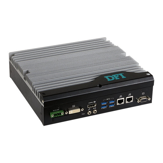
Front View
Antenna holes
Rear View
Note:
This port can be in HDMI or DP++ (DP++ available upon request).
DFI reserves the right to change the specifications at any time prior to the product's release. For the latest revision and details of the
installation procedure, please refer to the user's manual.
Package Contents
Panel
Power Button
Status LED (Orange)
HDD LED (Red)
USB 2.0
Reset Button
Antenna holes
DVI-D
(DVI-I connector)
DC-in
HDMI*
CFast
Microphone
Line-out
1
www.dfi.com
Extended Power
on/off Switch
COM 4
COM 2
COM 1
USB 3.0
LAN 1
LAN 2
COM 3
Antenna holes
VGA
Advertisement
Table of Contents

Related Manuals for DFI EC500-KH


Summary of Contents for DFI EC500-KH
- Page 1 This port can be in HDMI or DP++ (DP++ available upon request). DFI reserves the right to change the specifications at any time prior to the product's release. For the latest revision and details of the installation procedure, please refer to the user's manual.
-
Page 2: Removing The Chassis Cover
Removing the Chassis Cover Please observe the following guidelines before starting any installation procedures. 1. Make sure the system and all other peripherals connected to it have been powered off. 2. Disconnect all power cords and cables. To open the system, remove the 6 mounting screws on the on the left side, right side and bottom of the system. - Page 3 3. Lift the cover upward to open the system. 4. The SODIMM sockets, Mini PCIe and M.2 slots and SATA drive bay can be easily accessed after the chassis cover is removed. SODIMM socket SATA drive bay M.2 slot SIM card slot Mini PCIe slot...
-
Page 4: Installing A Sodimm
Installing a SODIMM Grasp the memory module by its edges and align the module’s notch with the socket’s notch; then insert the memory into the socket at an angle and push it down until you feel a click. Insert the memory at an angle SODIMM module installed into the... -
Page 5: Installing An M.2 Card
Installing an M.2 Card The onboard M.2 Type 2280 connector (M Key) supports PCIe NVMe modules up to PCIe Gen 3.0 x4 bandwidth. Note that only SKUs with Intel QM175 ® Chipset support M.2 socket. To install an M.2 card, insert the bottom edge of the M.2 card into the connector, and then secure the card to the standoff with the provided mounting screw. - Page 6 Installing a 2.5” SATA Drive The system can accommodate one SATA drive. Please use the following procedure to install a SATA drive in the system. 1. Before installing the SATA drive, connect the SATA data and power cable to the SATA data connector of the SATA drive. Then install the SATA drive onto the HDD bracket with the provided mounting screws.
- Page 7 3. Connect the other end of the SATA data and power cable to the SATA data and power connectors on the system board respectively. SATA data connector SATA power connector...
-
Page 8: Installing A Cfast Card
Installing a CFast Card The CFast slot is located on the rear panel and can be accessed without opening the system chassis. 1. Before installing a CFast card, take off the CFast card slot cover. CFast slot cover 2. Gently insert the CFast card straight with the label on the CFast card facing up until you feel it lock into place. - Page 9 Installing a Mini PCIe Card and a SIM Card The system board is equipped with 2 Mini PCIe slots with SIM card sockets to support a variety of wireless LAN and mobile broadband communication modules. Mini PCIe slot 1 provides both USB and PCIe interfaces whereas Mini PCIe slot 2 provides only USB interface.
- Page 10 Installing a SIM Card Open the SIM card socket by pushing the white latch inward. Push the latch inward to open it Insert the SIM card into the slot. Please place the card with the IC facing down and the angled corner aligning with the socket's angled corner so it will be cor- rectly in contact with the system board.
-
Page 11: Board Layout And Jumper Settings
JP16. 1-2 On 3. When COM3 RS232/422/485 is selected, JP12 and JP18 5V_Standby 2-3 On must be set in accordance to JP5. 4. When COM4 RS232/422/485 is selected, JP6 and JP19 must be set in accordance to JP13. A51500837 www.dfi.com...
Need help?
Do you have a question about the EC500-KH and is the answer not in the manual?
Questions and answers