Table of Contents
Advertisement
Quick Links
Advertisement
Table of Contents

Subscribe to Our Youtube Channel
Related Manuals for Arcteq AQ-200 Series


Summary of Contents for Arcteq AQ-200 Series
- Page 1 AQ-T216 Transformer protection IED Instruction manual ...
-
Page 2: Table Of Contents
6.1.3. ModbusIO ............© Arcteq Relays Ltd... - Page 3 9.2.2.2. Object control (OBJ) ........© Arcteq Relays Ltd...
- Page 4 11. Contact and reference information ..........© Arcteq Relays Ltd...
- Page 5 Nothing contained in this document shall increase the liability or extend the warranty obligations of the manufacturer Arcteq Relays Ltd. The manufacturer expressly disclaims any and all liability for any damages and/or losses caused due to a failure to comply with the instructions contained herein or caused by persons who do not ful l the aforementioned requirements.
- Page 6 AQ-T216 Instruction manual Version: 2.00 Copyright Copyright © Arcteq Relays Ltd. 2018. All rights reserved. © Arcteq Relays Ltd...
-
Page 7: Manual Revision Notes
- Added Programmable Control Switch and Indicator Object descriptions - Order code updated Changes - Voltage regulator function description revised. Added curve scaling example. - Programmable stage description added Revision 1.05 Date 14.8.2018 Changes - Added mA output option card description and ordercode © Arcteq Relays Ltd... -
Page 8: Abbreviations
RMS – Root mean square SF – System failure TMS – Time multiplier setting TRMS – True root mean square VAC – Voltage alternating current VDC – Voltage direct current SW – Software uP - Microprocessor © Arcteq Relays Ltd... -
Page 9: General
IO requirements and the software determines the available functions. This manual describes the speci c application of the AQ-T216 Transformer Protection IED. For other AQ-200 series products please consult corresponding device manuals. © Arcteq Relays Ltd... -
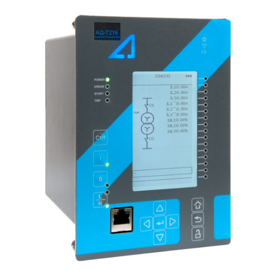
Page 10: Ied User Interface
This can be either a hardware or software error. Start LED (yellow) and Trip LED (red) activation is user settable. Activation and color (green/yellow) of the 16 LEDs on the right side of the display are user settable. © Arcteq Relays Ltd... -
Page 11: Mimic And Main Menu
All the settings in this IED type have been divided into main con guration menus. Main con guration menus are presented below. Available menus may vary according to IED type. Figure. 4.2.2. - 3. Main con guration menus. © Arcteq Relays Ltd... -
Page 12: General Menu
Protection/Control/Monitor pro le: Displays the status of enabled functions. 4.4. Protection menu Protection menu includes Stage activation sub-menu and sub-menus for different protection functions like Overcurrent, Earthfault, Seq. and balance and Supporting. Valid protection functions vary according IED type. © Arcteq Relays Ltd... - Page 13 Activation of different protection stages is done in Stage activation –sub menu. Each protection stage and supporting function is disabled as standard. Activated menus will appear below the stage speci c sub-menu for example I> appears below Current –module, U< appears below Voltage-module etc. EXAMPLE PROTECTION STAGE © Arcteq Relays Ltd...
- Page 14 AQ-T216 Instruction manual Version: 2.00 Figure. 4.4. - 7. Stage navigation and modi cation. Each protection stage and supportive function has ve stage menus Info, Settings, Registers, IO and Events. © Arcteq Relays Ltd...
- Page 15 Info view has calculator for function starts, trips and blockings. It is possible to clear calculators by choosing Clear statistics and Clear. Measurements are visible in Info menu. Active setting group and its settings are all visible in Info menu. © Arcteq Relays Ltd...
- Page 16 Stage settings vary according different protection functions. With factory settings only one group of eight is activated. To enable more groups go to Control menu and select Setting Groups. Figure. 4.4. - 10. Stage information is divided into two sections. © Arcteq Relays Ltd...
- Page 17 Connection to outputs can be either latched |x| or non-latched x. Stage blocking is done in Blocking Input Control menu. Blocking can be done by using digital inputs, logical inputs or outputs, stage start- trip- or blocked information or by using object status information. © Arcteq Relays Ltd...
- Page 18 Activation of different protection stages is done in Stage activation –sub menu. Each protection stage and supporting function is disabled as standard. Activated menus will appear below the stage speci c sub-menu for example I> appears below Current –module, U< appears below Voltage-module etc. © Arcteq Relays Ltd...
- Page 19 AQ-T216 Instruction manual Version: 2.00 Example protection stage Figure. 4.4. - 14. Stage navigation and modi cation. Each protection stage and supportive function has ve stage menus Info, Settings, Registers, IO and Events. © Arcteq Relays Ltd...
- Page 20 Info view has calculator for function starts, trips and blockings. It is possible to clear calculators by choosing Clear statistics and Clear. Measurements are visible in Info menu. Active setting group and its settings are all visible in Info menu. Other setting groups can be set in the Settings -menu. © Arcteq Relays Ltd...
- Page 21 Figure. 4.4. - 16. All group speci c settings are done individually in Settings menu. Stage settings vary according different protection functions. With factory settings only one group of eight is activated. To enable more groups go to Control menu and select Setting Groups. © Arcteq Relays Ltd...
- Page 22 Operation log can be cleared by choosing Clear registers → Clear . Events generated by the speci c stage can be checked by going to Stage event register. General events cannot be cleared. © Arcteq Relays Ltd...
- Page 23 Connection to outputs can be either latched |x| or non-latched x. Stage blocking is done in Blocking Input Control menu. Blocking can be done by using digital inputs, logical inputs or outputs, stage start- trip- or blocked information or by using object status information. © Arcteq Relays Ltd...
-
Page 24: Control Menu
Control menu includes Controls Enabled sub-menu and sub-menus for different control functions like Setting Groups, Objects, Control Functions and Device IO. Valid control functions vary according IED type. Figure. 4.5. - 20. Control menu view. Functions vary according IED type. © Arcteq Relays Ltd... - Page 25 RTDs and object status information can be used. Event masking for setting groups (masks are off as default). Only masked events appear to event list. Events cannot be cleared. © Arcteq Relays Ltd...
- Page 26 Figure. 4.5. - 23. Group changing with pulse control only or with pulses and static signal. Objects Figure. 4.5. - 24. Object controlling. Each activated object is visible in Objects -menu. As default all objects are disabled. Each active object has four setting menus, settings, application control, registers and events. © Arcteq Relays Ltd...
- Page 27 Ready- and external Synchrocheck permission have status inputs as well. Digital inputs, Logical inputs or outputs, stage starting- tripping- or blocking, RTDs and object status information can be used to indicate the status. Object open- and close signals of an object are connected to physical output relays. © Arcteq Relays Ltd...
- Page 28 LED. Connection to outputs can be either latched |x| or non-latched x. Object blocking is done in Blocking Input Control menu. Blocking can be done by using digital inputs, logical inputs or outputs, stage start- trip- or blocked information or by using object status information. © Arcteq Relays Ltd...
- Page 29 Control functions Figure. 4.5. - 28. Stage navigation and modi cation. Each enabled control function is listed below Control Functions menu. Every function includes same sub-menus as protections stages including Info, Settings, Registers, IO and Events. © Arcteq Relays Ltd...
- Page 30 (normal open or normal closed), activation (16…200 , step 0.1V) and release (10…200 V , step 0.1V) threshold voltage for each available input AC/DC AC/DC and activation delay (0…1800 s, step 1ms). Binary input statuses can be check from corresponding menu. © Arcteq Relays Ltd...
- Page 31 IED via setting le. NOTE! Normal closed signal goes to default position (normal open) in case the relay loses the auxiliary voltage or during System full reset. Normally closed output signal does not open during Communication- or protections reset. © Arcteq Relays Ltd...
- Page 32 Description Settings menu the label text of the LED can be modi ed. This label is visible in LEDs quick displays and matrixes. LED color can be chosen between green and yellow in LED Color Settings menu. As default the color is green. © Arcteq Relays Ltd...
- Page 33 Programmable control switches (PCS) are switches that can be used to control signals in mimic view. These signals can be used in various situations (controlling logic program, function blocking etc.) You can give each switch a name and set access level to determine who can control the switch. © Arcteq Relays Ltd...
-
Page 34: Communication Menu
Connections menu. IEDs support following communication protocols: SNTP, IEC61850, ModbusTCP, ModbusRTU, IEC103, IEC101/104, SPA and ModbusIO as a standard. It is also possible to have additional protocols with special extra communication interface modules. © Arcteq Relays Ltd... - Page 35 ModbusTCP can be used at the same time with other Ethernet based protocols like SNTP and IEC61850. ModbusRTU / IEC103 / ModbusIO con guration menus. ModbusRTU like other serial protocols can be used only one at the time over one physical serial communication interface. © Arcteq Relays Ltd...
-
Page 36: Measurement Menu
It is possible to individually invert polarity of each phase current. Transformers menu also displays more information like scaling factors for CTs and per unit values. FREQUENCY © Arcteq Relays Ltd... - Page 37 Per-unit group has values for fundamental component, TRMS, amplitude- and power THD and peak- to peak values. Primary group has values for fundamental component and TRMS and same applies with Secondary group. Phase Angle group displays the angle of each measured component. © Arcteq Relays Ltd...
- Page 38 Harmonics menu displays voltage and current harmonics from fundamental component up to 31th harmonic. It is possible to select whether each component is displayed as Absolute- or Percentage and as primary or secondary amps or per unit values. PHASORS © Arcteq Relays Ltd...
-
Page 39: Monitoring Menu
Monitoring menu includes Monitoring Enabled, Monitoring Functions, Disturbance REC and Device Diagnostics sub-menus. Valid Monitor functions vary according IED type. Figure. 4.8. - 44. Monitoring menu view. Monitor functions vary according IED type. MONITORS ENABLED Figure. 4.8. - 45. IED Monitors Enabled sub- menu. © Arcteq Relays Ltd... - Page 40 Activated menus will appear in the Monitor functions sub-menu. MONITOR FUNCTIONS Figure. 4.8. - 46. IED function modi cation. Con guring monitor functions is very similar to con guring protection stages. DISTURBANCE REC © Arcteq Relays Ltd...
- Page 41 Recording mode is either First in First out or Keep Olds. Sample rate of analogue channels is 8/16/32/62 samples per cycle. Digital channel sample rate is xed 5 ms. Pre triggering time is selectable between 5…95%. © Arcteq Relays Ltd...
- Page 42 Device Diagnostics gives detailed feedback of the IED condition generally and whether option cards are installed correctly without problems. In case anything abnormal is noticed in Device diagnostics menu and it cannot be reset please contact closest representative or manufacturer. © Arcteq Relays Ltd...
-
Page 43: User Level Password Con Guration
Con gurator: Can change most settings like basic protection pick-up levels or time delays, breaker control functions, signal descriptions etc. Can operate breakers or other equipment. Super user: Access to change any setting and can operate breakers or other equipment. © Arcteq Relays Ltd... -
Page 44: Functions
ANSI Description Set group settings Object control Table. 5.1. - 3. Monitoring functions of AQ-T216 Name ANSI Description Current transformer supervision, 2 sides Disturbance recorder Circuit breaker wear monitor Total harmonic distortion VREC Measurement value recorder © Arcteq Relays Ltd... -
Page 45: Measurements
MVA and nominal voltage on each winding. For the measurements to be correct it needs to be made sure that the measurement signals are connected to correct inputs, current direction is connected correctly and the scaling is set correctly. © Arcteq Relays Ltd... - Page 46 In following chapter is given example for the scaling of the relay measurements to the example current transformers and nominal load. CT scaling example (application 1) The connection of CTs to the IED measurement inputs and the ratings of the current transformers and transformer nominal current are as in following gure. © Arcteq Relays Ltd...
- Page 47 Protection → TrafoModule → Idx> [87T,87N] → Settings has to be set as “Subtract”. Due to this the direction of measured currents are checked correctly from the relay perspective. Initial data of the connection and the ratings are presented in following table. © Arcteq Relays Ltd...
- Page 48 As it can be seen in the gure above, the high voltage side nominal current is calculated to be 669.2A and the low voltage side current is 5888.97A. These nominal currents are calculated as follow: Per unit values for high –and low voltage side nominal currents can be calculated as shown below: © Arcteq Relays Ltd...
- Page 49 Figure. 5.2.1. - 54. Residual current I02 scaling to ring core CT input. CT scaling example (application 2) The connection of CTs to the IED measurement inputs and the ratings of the current transformers and transformer nominal current are as in following gure. © Arcteq Relays Ltd...
- Page 50 Initial data of the connection and the ratings are presented in following table. Table. 5.2.1. - 5. Initial data from example connection. Machine nominal power: 153MVA Machine high voltage side nominal amplitude: 132kV Machine low voltage side nominal amplitude: 15kV © Arcteq Relays Ltd...
- Page 51 1:Object p.u. MACHINE PROTECTION). In p.u. Phase CT 1… 0.1A 100.0A Rated primary current of the CT in amperes. primary 5000.0A Phase CT 0.2… 0.1A 5.0A Rated secondary current of the CT in amperes. secondary 10.0A © Arcteq Relays Ltd...
- Page 52 IED feedback value, this is the calculated scaling factor for primary /secondary factor P/S current ratio Measurements Following measurements are available from the measured current channels. Table. 5.2.1. - 9. Per unit phase current measurements Name Range Step Description © Arcteq Relays Ltd...
- Page 53 Primary residual 0.00… Primary measurement from residual current channel I01 fundamental 0.01A current I01 1000000.0A frequency RMS current. Primary residual 0.00… Primary measurement from residual current channel I02 fundamental 0.01A current I02 1000000.0A frequency RMS current. © Arcteq Relays Ltd...
- Page 54 Table. 5.2.1. - 19. Secondary sequence current measurements Name Range Step Description Secondary Positive sequence 0.00… Secondary measurement from calculated positive sequence 0.01A current 300.0A current Secondary Negative sequence 0.00… Secondary measurement from calculated negative sequence 0.01A current 300.0A current © Arcteq Relays Ltd...
-
Page 55: Frequency Tracking And Scaling
Measurement error with xed 50Hz sampling frequency when Measurement error with frequency tracking when frequency changes. Constant current of 5A, frequency sweep frequency changes. Constant current of 5A, frequency from 6 Hz to 75 Hz sweep from 6 Hz to 75 Hz © Arcteq Relays Ltd... - Page 56 FFT calculation has always whole power cycle in the buffer. Further improvement for the achieved measurement accuracy is the Arcteq patented method of calibrating of the analog channels against 8 system frequency points for both, magnitude and angle. This frequency dependent correction compensates the used measurement hardware frequency dependencies.
-
Page 57: General Menu
If external clock time synchronization source is available, the type is 1:External Timesync. de ned with this parameter. In internal mode there is no external 0:Internal source Timesync source. IRIG-B requires serial ber communication option 2:External card. Serial 3:IRIG-B © Arcteq Relays Ltd... -
Page 58: Protection Functions
5.4. Protection functions 5.4.1. General properties of a protection function Following flowchart is describes the basic structure of any protection function. Basic structure is composed of analog measurement value comparison to the pick-up values and operating time characteristics. © Arcteq Relays Ltd... - Page 59 Instruction manual Version: 2.00 Protection function is run in a completely digital environment with protection CPU microprocessor which also processes the analog signals transferred to digital form. Figure. 5.4.1. - 56. Principle diagram of protection relay platform. © Arcteq Relays Ltd...
- Page 60 The pick-up activation of the function is not directly equal to start-signal generation of the function. Start signal is allowed if blocking condition is not active. Figure. 5.4.1. - 58. Measurement range in relation to the nominal current. © Arcteq Relays Ltd...
- Page 61 IDMT mode De nite (Min) operating time delay is also in use de ning the minimum time for protection tripping. If this function is not desired this parameter should be set to 0 seconds. © Arcteq Relays Ltd...
- Page 62 Moderately Inverse, Very Inverse, Extremely Inverse characteristics. Param IEEE MI IEEE selection allows the tuning of the constants A, B and C which allows IEEE VI setting of characteristics following the same formula as the IEEE curves IEEE EI mentioned here. Param © Arcteq Relays Ltd...
- Page 63 Constant B for IEC/IEEE characteristics. Setting is active and visible when Delay Type is selected to IDMT. 0.0000… 0.0001 0.0200 250.0000 Constant C for IEEE characteristics. Figure. 5.4.1. - 60. Inverse operating time formulas for IEC and IEEE standards. © Arcteq Relays Ltd...
- Page 64 AQ-T216 Instruction manual Version: 2.00 Figure. 5.4.1. - 61. De nite time operating characteristics. © Arcteq Relays Ltd...
- Page 65 AQ-T216 Instruction manual Version: 2.00 Figure. 5.4.1. - 62. IEC prede ned characteristics NI, VI, LTI and EI © Arcteq Relays Ltd...
- Page 66 AQ-T216 Instruction manual Version: 2.00 Figure. 5.4.1. - 63. IEEE ANSI prede ned characteristics EI, LTI, NI and VI © Arcteq Relays Ltd...
- Page 67 AQ-T216 Instruction manual Version: 2.00 Figure. 5.4.1. - 64. IEEE prede ned characteristics EI, MI and VI © Arcteq Relays Ltd...
- Page 68 IEC or IEEE standards. These functions are Overcurrent stages, Residual overcurrent stages, Directional overcurrent stages and Directional residual overcurrent stages. The setting parameters and their ranges are documented in the function blocks respective chapters. © Arcteq Relays Ltd...
- Page 69 Time calculation characteristics selection. If activated the operating time during release counter is continuing until set release time even the pick-up element is reset. time Behavior of stages with different release time con gurations are presented in the following gures. © Arcteq Relays Ltd...
- Page 70 AQ-T216 Instruction manual Version: 2.00 Figure. 5.4.1. - 66. No delayed pick-up release. Figure. 5.4.1. - 67. Delayed pick-up release, delay counter is reset at signal drop-off. © Arcteq Relays Ltd...
- Page 71 Figure. 5.4.1. - 69. Delayed pick-up release, delay counter value is decreasing during the release time. Resetting characteristics can be set according to the application. Default setting is delayed with 60 ms and the time calculation is held during the release time. © Arcteq Relays Ltd...
-
Page 72: Non-Directional Overcurrent I> (50/51)
START and TRIP events simultaneously with equivalent time stamp. Time stamp resolution is 1ms. Function provides also cumulative counters for START, TRIP and BLOCKED events. In the following gure is presented the simpli ed function block diagram of the NOC function. © Arcteq Relays Ltd... - Page 73 Table. 5.4.2. - 30. General settings of the function Name Description Range Step Default 1:Disabled Setting control from Activating this parameter permits changing the pick-up level of the 1:Disabled comm bus protection stage via SCADA. 2:Allowed © Arcteq Relays Ltd...
- Page 74 User settable variables are binary signals from the system. Blocking signal needs to reach the IED minimum of 5 ms before the set operating delay has passedfor blocking to be active in time. © Arcteq Relays Ltd...
- Page 75 Start OFF 1346 NOC2 Trip ON 1347 NOC2 Trip OFF 1348 NOC2 Block ON 1349 NOC2 Block OFF 1350 NOC2 Phase A Start On 1351 NOC2 Phase A Start Off 1352 NOC2 Phase B Start On © Arcteq Relays Ltd...
- Page 76 1480 NOC4 Phase B Start On 1481 NOC4 Phase B Start Off 1482 NOC4 Phase C Start On 1483 NOC4 Phase C Start Off 1484 NOC4 Phase A Trip On 1485 NOC4 Phase A Trip Off © Arcteq Relays Ltd...
-
Page 77: Non-Directional Earth Fault I0> (50N/51N)
START and TRIP events simultaneously with equivalent time stamp. Time stamp resolution is 1ms. Function provides also cumulative counters for START, TRIP and BLOCKED events. In the following gure is presented the simpli ed function block diagram of the NEF function. © Arcteq Relays Ltd... - Page 78 SCADA 2:Allowed 1:RMS De nes which available measured magnitude is used by the 2:TRMS Measured magnitude 1:RMS function 3:Peak-to- peak 1:Side1 De nes which current measurement module is used by the Meas side 1:Side1 function. 2:Side2 © Arcteq Relays Ltd...
- Page 79 Operating time characteristics for trip and reset This function supports de nite time delay (DT) and inverse de nite minimum time (IDMT) delay types. For detailed information on these delay types refer to chapter General properties of a protection function. © Arcteq Relays Ltd...
- Page 80 Fault Prefault Trip time Used Date & Time code type current current current remaining dd.mm.yyyy 1664-1861 A-G-R… Start average Trip -20 ms Start -200 ms 0ms -1800s 1 - 8 hh:mm:ss.mss Descr. C-G-F current averages averages © Arcteq Relays Ltd...
-
Page 81: Current Unbalance I2
1ms. Function provides also cumulative counters for START, TRIP and BLOCKED events. In the following gure is presented the simpli ed function block diagram of the CUB function. Figure. 5.4.4. - 71. Simpli ed function block diagram of the CUB function. © Arcteq Relays Ltd... - Page 82 Ixset value. The reset ratio is common for both modes. Table. 5.4.4. - 42. Pick-up characteristics setting Name Description Range Step Default I2set Pick-up setting for I2 mode 0.01…40.00xIn 0.01xIn 0.2xIn I2/I1set Pick-up setting for I2/I1 mode 1…200% 0.01% © Arcteq Relays Ltd...
- Page 83 Uniquely to current unbalance protection there is also “Curve2” delay available which follows the formula below: t = Operating time = Calculated negative sequence 2meas = Nominal current k = Constant k value (user settable delay multiplier) = Pick-up setting of the function © Arcteq Relays Ltd...
- Page 84 RI-type Non-standard RI-type, RD-type and Curve2 delay char. Curve2 Setting is active and visible when Delay Type is selected to IDMT. Time dial 0.01…25.00s 0.01s 0.05s setting k Time dial / multiplier setting for IDMT characteristics. © Arcteq Relays Ltd...
- Page 85 Event block name Event Code Description 2048 CUB1 Start ON 2049 CUB1 Start OFF 2050 CUB1 Trip ON 2051 CUB1 Trip OFF 2052 CUB1 Block ON 2053 CUB1 Block OFF 2112 CUB2 Start ON 2113 CUB2 Start OFF © Arcteq Relays Ltd...
-
Page 86: Harmonic Overcurrent Ih> (50H/51H/68H)
Start signal can be used for blocking other stages while in cases when the situation prolongs can Trip signal be used for other actions as time delayed. For IDMT operation IEC and ANSI standard time delays are supported as well as custom parameters. © Arcteq Relays Ltd... - Page 87 Magnitudes (rms) of phase L2/B current components: Fundamental, 2 harmonic, 3 harmonic, 4 IL2FFT 5 ms harmonic, 5 harmonic 7 , harmonic 9 , harmonic 11 , harmonic 13 , harmonic 15 , harmonic 17 harmonic 19 harmonic current. © Arcteq Relays Ltd...
- Page 88 (Im) per all three phases. Reset ratio of 97 % is inbuilt in the function and is always related to the Ihset / Ih/IL value. The setting value is common for all measured phases and single-, dual- or all phases Im exceed of the Iset value will cause pick-up operation of the function. © Arcteq Relays Ltd...
- Page 89 Table. 5.4.5. - 50. Event codes of the HOC function instances. Event Number Event channel Event block name Event Code Description 2368 HOC1 Start ON 2369 HOC1 Start OFF 2370 HOC1 Trip ON 2371 HOC1 Trip OFF 2372 HOC1 Block ON © Arcteq Relays Ltd...
-
Page 90: Circuit Breaker Failure Protection Cbfp (50Bf)
In signal dependent mode any of the IED binary signal can be used for triggering the CBFP. In binary output dependent mode CBFP monitors selected output relay control signal status. Blocking signal and setting group selection controls the operating characteristics of the function during normal operation. © Arcteq Relays Ltd... - Page 91 Fundamental RMS measurement of residual input I02 5 ms I0Calc Calculated residual current from the phase current inputs 5 ms DOIN Monitoring of the digital output relay status 5 ms DIIN Monitoring of digital input status 5 ms © Arcteq Relays Ltd...
- Page 92 0.20 x In 40.00xIn upper limit for the phase current pick-up element. 0.005 … Pick-up threshold for residual current measurement. This setting limit de nes I0set 0.001xIn 1.200xIn 40.000xIn the upper limit for the phase current pick-up element. © Arcteq Relays Ltd...
- Page 93 CBFP start timer, this setting de nes how long the starting condition has to last CBFP 0.005s 0.200s 1800.000s before CBFP signal is activated. A few typical cased of CBFP are presented in the following gures. © Arcteq Relays Ltd...
- Page 94 Retrip is wired in parallel from its own output contact in the IED to the second tripping coil of the circuit breaker. CBFP signal to upstream is wired normally from its output contact in the IED to the upstream / incomer breaker. In following are few operational cases presented regarding to the different applications. © Arcteq Relays Ltd...
- Page 95 CBFP will be issued to upstream breaker. If the primary protection function clears the fault e.g. the circuit breaker operates normally the counters for retrip and CBFP are reset immediately the current is measured below the threshold settings. © Arcteq Relays Ltd...
- Page 96 This con guration allows the CBFP to be controlled on current based functions only and other function trips can be excluded from the CBFP functionality. © Arcteq Relays Ltd...
- Page 97 This con guration allows the CBFP to be controlled on current based functions with added security from the current monitoring of the CBFP function and other function trips can be also included to the CBFP functionality. © Arcteq Relays Ltd...
- Page 98 Probably the most common application is the case where the circuit breaker trip coil is controlled with the IED trip output and CBFP is controlled with one dedicated CBFP contact. In following are few operational cases presented regarding to the different applications and settings of the CBFP function. © Arcteq Relays Ltd...
- Page 99 CBFP will be issued to upstream breaker. If the primary protection function clears the fault e.g. the circuit breaker operates normally the counter for CBFP are reset immediately the current is measured below the threshold settings. © Arcteq Relays Ltd...
- Page 100 This con guration allows the CBFP to be controlled on current based functions only and other function trips can be excluded from the CBFP functionality. © Arcteq Relays Ltd...
- Page 101 This con guration allows the CBFP to be controlled on current based functions with added security from the current monitoring of the CBFP function and other function trips can be also included to the CBFP functionality. © Arcteq Relays Ltd...
- Page 102 CBFP for the upstream breaker tripping. In this example no retripping is utilized and CBFP signal is used for the incomer trip from the outgoing breaker trip signal. The trip signal can be transported in between of the IED:s also by using GOOSE messages if so wanted. © Arcteq Relays Ltd...
- Page 103 Table. 5.4.6. - 57. Event codes of the CBFP function instance Event Number Event channel Event block name Event Code Description 2816 CBF1 Start ON 2817 CBF1 Start OFF 2818 CBF1 Retrip ON 2819 CBF1 Retrip OFF 2820 CBF1 CBFP ON © Arcteq Relays Ltd...
-
Page 104: Restricted Earth Fault / Cable End Differential (Ref) I0D> (87N)
ON/OFF events to the common event buffer from each of the two output signals. Time stamp resolution is 1ms. Function provides cumulative counters for REF Trip and BLOCKED events. In the following gure is presented the simpli ed function block diagram of the REF function. © Arcteq Relays Ltd... - Page 105 The following general settings de ne the general behavior of the function. These settings are static i.e. it is not possible change them with setting group switching. Table. 5.4.7. - 60. General settings of the REF stage (not SG selectable) Name Range Step Default Description © Arcteq Relays Ltd...
- Page 106 The pick-up activation of the function is not directly equal to trip-signal generation of the function. Trip signal is allowed if blocking condition is not active. In the following gure is presented the differential characteristics with default settings. © Arcteq Relays Ltd...
- Page 107 Blocking signal is received from the blocking matrix for the function dedicated input. If the blocking signal is not activated when the pick-up element activates, a Trip signal is generated and the function proceeds to the time characteristics calculation. © Arcteq Relays Ltd...
- Page 108 When the current natural unbalance is compensated in this same situation the differential settings may be set more sensitive and the natural unbalance does not affect into the calculation. Figure. 5.4.7. - 88. Cable end differential when fault happens. © Arcteq Relays Ltd...
- Page 109 If the fault is located inside of the transformer and thus inside of the protection area the REF function catches the fault with high sensitivity since the measured residual current directions are now opposite for the outside fault situation the measured differential current is high. © Arcteq Relays Ltd...
- Page 110 Table. 5.4.7. - 63. Register content Residual Used Date & Time Event code Trigger currents Trigger currents currents Biascurrent trig Biascurrent max dd.mm.yyyy 4224-4227 Diffcurrent trig Diffcurrent max I0Calc 1 - 8 hh:mm:ss.mss Descr. Characteristics diff Characteristics diff I0 meas trig © Arcteq Relays Ltd...
-
Page 111: Transformer Status Monitoring (Trf)
Figure. 5.4.8. - 91. Simpli ed function block diagram of the TRF function. The TRF function outputs are dependent of the set transformer data in that sense that per unitized measured currents are related to transformer nominal values. Following diagram presents the TRF function outputs in various situations. © Arcteq Relays Ltd... - Page 112 LV side nominal voltage of the transformer. This value nominal 0.1…500.0kV 0.1kV 110.0kV is used to calculate nominal currents of LV side. voltage Transformer Transformer short circuit impedance in %. Used for 0.01…25.00% 0.01% 3.00% Info calculation of the short circuit currents © Arcteq Relays Ltd...
- Page 113 Selection is visible only if vector group is set to “0:Manual set” Table. 5.4.8. - 65. Calculations of the TRF function. Name Range Step Default Funcs. Description HV side nominal Calculated transformer HV side primary 0.01...50000.00A 0.01A 0.00A Info current(pri) current. © Arcteq Relays Ltd...
- Page 114 TRF function generates events from detected transformer energizing status. From changes of the events also data register is available. Table. 5.4.8. - 67. Event codes of the TRF function Event Number Event channel Event block name Event Code Description © Arcteq Relays Ltd...
-
Page 115: Transformer Thermal Overload Protection Tt> (49Tr)
θ = Thermal image status in percent of the maximum thermal capacity available θ = Thermal image status in previous calculation cycle (the memory of the function) = Measured maximum of the three TRMS phase currents © Arcteq Relays Ltd... - Page 116 100% but never exceeds it. With a single time constant model cooling of the object follows this same behavior reversible to the heating when the current feeding is completely zero. Figure. 5.4.9. - 93. Thermal image calculation with nominal conditions, example. © Arcteq Relays Ltd...
- Page 117 = Ambient temperature correction factor for the minimum temperature = Ambient temperature reference (can be set in ̊ C or ̊ F , the temperature in which the given manufacturer presumptions apply and the temperature correction factor is 1.0) © Arcteq Relays Ltd...
- Page 118 ON/OFF events to the common event buffer from each of the two output signal. Time stamp resolution is 1ms. Function provides also cumulative counters for TOLT Trip, Alarm 1, Alarm 2, Inhibit and BLOCKED events. In the following gure is presented the simpli ed function block diagram of the TOLT function. © Arcteq Relays Ltd...
- Page 119 Time constant setting. This time constant is used for cooling of the protected 0.1min 10.0min const) 500.0min object. 0.01… Service factor which corrects the maximum allowed current value according to (service 0.01 1.00 5.00 installation etc. conditions which vary from the presumption conditions. factor) © Arcteq Relays Ltd...
- Page 120 The operating characteristic of the TOLT function is completely controlled by the thermal image. From the thermal image calculated thermal capacity used value can be set IO controls with Alarm 1, Alarm 2, Inhibit and Trip signals. © Arcteq Relays Ltd...
- Page 121 5 ms before the set operating delay has passedfor blocking to be active in time. Measurements and indications of the function TOLT function outputs measured process data from following magnitudes: Table. 5.4.9. - 74. General status codes Name Range Description © Arcteq Relays Ltd...
- Page 122 Table. 5.4.9. - 77. Event codes of TOLT function. Event Number Event channel Event block name Event Code Description 4672 TOLT1 Alarm1 On 4673 TOLT1 Alarm1 Off © Arcteq Relays Ltd...
-
Page 123: Transformer Differential Idb> Idi> I0Dhv> I0Dlv> (87T,87N)
“good enough” protection. Following table gives a rough idea about protection methods and elements, which should be considered for each type of transformer, e.g. protection design below these mentioned suggestions increase risk of having costly problems with transformer. Transformer Risks Protection © Arcteq Relays Ltd... - Page 124 Faults of this type are easily repaired, and the transformer can be energized quickly after the fault is cleared. © Arcteq Relays Ltd...
- Page 125 HV and LV side current transformer ratios and properties. In this chapter the setting and principle of transformer differential protection are shown step by step. Figure. 5.4.10. - 96. Transformer and its components forming the “differential zone”. © Arcteq Relays Ltd...
- Page 126 However below are the formulas to calculate the amplitude matching coef cients. Let’s say that in this example HV side CTs are 150/5A and LV side CTs are 1200/5A Primary side per unit factor and current calculation Secondary side per unit factor and current calculation © Arcteq Relays Ltd...
- Page 127 180 degree difference into these “1” and “11” clock numbers. In this example case the transformer current vectors and the transformer connection looks like in the following gure. © Arcteq Relays Ltd...
- Page 128 In this case in differential relay the differential function applies following translation to delta side currents (note that the correction is not only to the angles but also to the amplitudes since the per unitized delta side has relation amplitude difference to star connected side) © Arcteq Relays Ltd...
- Page 129 As mentioned now the differential algorithm itself, it has calculating formula per each phase difference: Subtracting formula: Or Additive formula: Can be selected based into the CTs connections. © Arcteq Relays Ltd...
- Page 130 For the restraint characteristics also so called “Bias” calculation is made per each phase to adjust the sensitivity of the differential stage up to the measured currents. For the bias calculation also two separate formulas are available. Average mode (sensitive biasing): © Arcteq Relays Ltd...
- Page 131 In this example the non-biased pick-up is set to quite low what it would be in normal transformer application. Settings and ranges of the differential protection are presented in the settings chapter. The biasing characteristic is formed with following formulas: © Arcteq Relays Ltd...
- Page 132 Secondary side CT measurement accuracy (CTE sec) Relay measurement accuracy (primary and secondary) (REm) Tap changer on load side (TCE) Possible auxiliary transformer or auxiliary winding, which currents are not measured separately (AUTE) Transformer core magnetizing current (TME) Safety margin (SME) © Arcteq Relays Ltd...
- Page 133 5 x 2.5% from the nominal conditions. So therefore TCE is in this case 12.5%. (Note that the tap position is not always necessarily nominal in center position, check from your application and calculate the maximum effect to worst side border). Figure. 5.4.10. - 105. Transformer tap changer © Arcteq Relays Ltd...
- Page 134 On the absolute measurement affecting factor is known the expected value as 1 xIn as well as it is correct that the tap changer is in maximum position thus causing the absolute measurement to be 1 xIn + TCE © Arcteq Relays Ltd...
- Page 135 Slope 1 is calculated by using the transformer and CT nominal values in the maximum full load (Turnpoint 2) of the transformer with highest possible differential current causing tap position. Generally Slope 1 setting is calculated as below: © Arcteq Relays Ltd...
- Page 136 For LV side currents will be And for HV side currents will be By calculating this way these currents now present the worst possible case caused by tap changer effect into the differential relay measured currents. © Arcteq Relays Ltd...
- Page 137 Slope 2 setting. If in case of using “Average” mode for biasing (in case of single end fault) the bias current will be , and the differential current will be directly © Arcteq Relays Ltd...
- Page 138 For our example case the LV side maximum three phase short circuit current would be: This current will be seen in HV side as: Now when looking at our example CT ratings: HV side: 150/5A 10P10 LV side: 1200/5A 5P10 Let’s calculate the secondary currents of this situation. © Arcteq Relays Ltd...
- Page 139 These values in this table present the resistivity in the given temperature +20ºC. For calculation of the conductor resistivity in other temperatures use following formula: These values in this table present the resistivity in the given temperature +20ºC. For calculation of the conductor resistivity in other temperatures use following formula: © Arcteq Relays Ltd...
- Page 140 Actual accuracy limit factor can be calculated as follows (this is common method): In this formula the S values are in VA. Biggest problem in this equation is to know the internal resistance of the CT secondary for calculation of the S CTRN © Arcteq Relays Ltd...
- Page 141 If the CTs would have possibility to saturate (calculated through fault current is bigger than the ALF of either side CT) the setting of the instant stage should be set high enough so that it will not operate on through fault saturation. © Arcteq Relays Ltd...
- Page 142 In this example the transformer used is very small, however the formulas presented in this manual can be applied to any size power transformers. In the TRF module, relay calculates these settings automatically if so wanted. Relay uses exactly these same formulas for the setting calculations. © Arcteq Relays Ltd...
- Page 143 Basically in between these presented restraint calculation modes the characteristics are now set to equally sensitive. Also the variations of Turnpoint1 setting either to 0.01xIn or 1.0xIn are presented (Figures A, C with Turnpoint 1 set to 1.00 xIn and B, D with Turnpoint 1 set to 0.01 xIn). © Arcteq Relays Ltd...
- Page 144 “N” or “n” representing either HV side or LV side grounding. What this selection actually does is that it deducts the calculated zero sequence current from the per- unitized currents before differential calculation thus negating the outside earth fault effect. © Arcteq Relays Ltd...
- Page 145 Restricted earth fault enabling requires that in addition to phase currents measurement also the starpoint current is available and can be connected to the residual current channel of the relay on corresponding (HV/LV) side measurement. © Arcteq Relays Ltd...
- Page 146 CT ratings). The tripping characteristics may be set differently in case if the network is directly grounded or through impedance and the fault current may be expected to saturate CTs in the external fault also. © Arcteq Relays Ltd...
- Page 147 (depending of the transformer properties) the flux shall be 90 degrees behind the winding voltage and the system is in steady state. © Arcteq Relays Ltd...
- Page 148 Basically this energization current shall be seen in the differential relay as a differential current since it will flow through the primary side winding only. For this purpose the 2 harmonic component generated by the saturation of the transformer core can be used to block the biased sensitive differential stage during energization. © Arcteq Relays Ltd...
- Page 149 (50 Hz) FFT calculated currents in amperes, and fth graph presents the relative 2 harmonic components to corresponding fundamental component currents with the 15% setting limit for display what the setting presents in this concept. © Arcteq Relays Ltd...
- Page 150 Now this result is still very low considering of the magnetizing inrush current magnitudes but still the differential relay would de nitely trip in this case if it would not be prevent from operating by 2 harmonic blocking. Situation is the same with all of the setting variations calculated. © Arcteq Relays Ltd...
- Page 151 15-20% harmonic content compared to fundamental frequency. Final tuning for the transformer settings can be made in commissioning if there should be any issues on problematic transformer energisation. © Arcteq Relays Ltd...
- Page 152 (which is used in the blocking). Also into the graph are plotted possible suggested setting limits for the harmonic detection (30%, 35% and 40%). In the second graph are plotted primary and secondary currents in function of the voltage and in the last graph the differential characteristics and differential/bias currents. © Arcteq Relays Ltd...
- Page 153 Based into the ratio check this however is not very failsafe way in order that to set it correctly and so that it could be more of use the magnetizing properties and hysteresis of the transformer should be completely known. © Arcteq Relays Ltd...
- Page 154 30-40% with disturbance recorder enabled. If there should happen anything related to tripping due to over excitation, settings may be adjusted based into the data captured by disturbance recorder. © Arcteq Relays Ltd...
- Page 155 Transformer short circuit impedance in %. Used for 0.01…25.00% 0.01% 3.00% Info calculation of the short circuit currents Transformer Transformer nominal frequency. Used for calculation of 10…75Hz 50Hz Info nom. freq transformer nominal short circuit inductance. © Arcteq Relays Ltd...
- Page 156 Selection is visible only if vector group is set to “0:Manual set” Enable I0d> 0:Disabled HV side restricted earth fault stage enable/disable (REF) HV 0: Disabled TRF,DIFF 1:Enabled selection. side © Arcteq Relays Ltd...
- Page 157 “Enable Idi>” stage is set to 1. Pickup Base sensitivity for the HV side restricted earthfault differential HV I0d> 0.01… 0.01% 10.00% characteristics Setting is visible only if “Enable I0d> (REF) HV side” is set to Pickup 100.00% “1: Enabled” © Arcteq Relays Ltd...
- Page 158 Trip output signal from the non-biased/non-blocked differential stage Idb> Bias Blocked Blocked output from the biased differential stage (external blocking) Idi> Bias Blocked Blocked output from the non-biased/non-blocked differential stage (external blocking) Idb> 2 harm block on Output of 2 harmonic activation signal © Arcteq Relays Ltd...
- Page 159 4567 DIF1 L3 5.th harm Off 4568 DIF1 HV I0d> Block On 4569 DIF1 HV I0d> Block Off 4570 DIF1 HV I0d> Trip On 4571 DIF1 HV I0d> Trip Off 4572 DIF1 LV I0d> Block On © Arcteq Relays Ltd...
-
Page 160: Resistance Temperature Detectors (Modbus Io) (Rtd) (49T)
Used measurement module is selected rst and the poll address. Module type needs to be set also as well as the polled channels. In case of thermocouple module the thermo element type needs to be set per each measurement channel. After these settings the RTD:s are available for other functions. © Arcteq Relays Ltd... - Page 161 Table. 5.4.11. - 87. Settings of the RTD function for channel x/12. Name Range Step Default Description 0:No Sx enable 0:No Enable / Disable selection of the sensor measurements and alarms 1:Yes 0:ModuleA Sx module 1:ModuleB 0:ModuleA Selection of the measurement module 2:ModuleC © Arcteq Relays Ltd...
- Page 162 S1 Alarm1 On 4417 RTD1 S1 Alarm1 Off 4418 RTD1 S1 Alarm2 On 4419 RTD1 S1 Alarm2 Off 4420 RTD1 S2 Alarm1 On 4421 RTD1 S2 Alarm1 Off 4422 RTD1 S2 Alarm2 On 4423 RTD1 S2 Alarm2 Off © Arcteq Relays Ltd...
- Page 163 S11 Alarm1 Off 4458 RTD1 S11 Alarm2 On 4459 RTD1 S11 Alarm2 Off 4460 RTD1 S12 Alarm1 On 4461 RTD1 S12 Alarm1 Off 4462 RTD1 S12 Alarm2 On 4463 RTD1 S12 Alarm2 Off 4464 RTD1 S13 Alarm1 On © Arcteq Relays Ltd...
- Page 164 S10 Meas Ok 4499 RTD2 S10 Meas Invalid 4500 RTD2 S11 Meas Ok 4501 RTD2 S11 Meas Invalid 4502 RTD2 S12 Meas Ok 4503 RTD2 S12 Meas Invalid 4504 RTD2 S13 Meas Ok 4505 RTD2 S13 Meas Invalid © Arcteq Relays Ltd...
-
Page 165: Arc Fault Protection Iarc>/I0Arc>(50Arc/50Narc)
Arc protection card has four sensor channels. Up to three arc point sensors may be connected to each channel. Sensor channels support Arcteq AQ-01 (light sensing) and AQ-02 (pressure and light sensing) units. Optionally protection function can be applied with phase or residual current condition. - Page 166 Example scheme setting The following examples enables better understanding of setting up the arc protection function. In the following cases AQ-101 models are used to extend the protection of Zone2 and to protect each outgoing feeder (Zone3). © Arcteq Relays Ltd...
- Page 167 100 series units. Parameter I/I0 Arc> Self supervision test pulse should be activated when connecting AQ-100 series units to AQ-200 series arc protection card to prevent the pulses from activating ArcB1. Next example is the same as in the rst one but this time each outgoing feeder has AQ-2xx protection relay instead of AQ-101 arc protection relay.
- Page 168 Arc protection uses sample based current measurement. If required number of samples is found over the setting limit current condition activates. It is possible to use either phase currents or residual current in the tripping decision. © Arcteq Relays Ltd...
- Page 169 5 ms before the set operating delay has passedfor blocking to be active in time. Events & registers The ARC function generates events and registers from the status changes of start, trip and blocked. To main event buffer it’s possible to select status “On” or “Off” messages. © Arcteq Relays Ltd...
- Page 170 4766 ARC1 Channel 2 Pressure On 4767 ARC1 Channel 2 Pressure Off 4768 ARC1 Channel 3 Light On 4769 ARC1 Channel 3 Light Off 4770 ARC1 Channel 3 Pressure On 4771 ARC1 Channel 3 Pressure Off © Arcteq Relays Ltd...
-
Page 171: Programmable Stage
“Activated”, the amount of programmable stages can be set anywhere between 1 to 10 depending on the need of the application. In the example below the amount of programmable stages have been set to 2, which results in PS1 and PS2 appearing. The inactive stages are hidden until they are activated. © Arcteq Relays Ltd... - Page 172 0.00866 multiplier inverses to 100%. This way pre-processed signal is easier to set, but it is also possible to just use scaling factor of 1.0 and set the desired pick-up limit as primary voltage. In the same way any chosen measurement value can be scaled to desired form. © Arcteq Relays Ltd...
- Page 173 Any of the signals need to ful ll the pick-up condition. Each signal has their own pick-up setting. Mag3 4:Mag1 AND Mag2 AND All of the signals need to ful ll the pick-up condition. Each signal has their own pick-up setting. Mag3 © Arcteq Relays Ltd...
- Page 174 4:Delta Relative change over time. If the measured signal changes more than the set relative pick-up value in 20ms, set(%) +/- > the comparison condition is ful lled. The condition is dependent on direction. © Arcteq Relays Ltd...
- Page 175 IL2 13th harmonic in per unit value IL2 15th h. IL2 15th harmonic in per unit value IL2 17th h. IL2 17th harmonic in per unit value IL2 19th h. IL2 19th harmonic in per unit value Description © Arcteq Relays Ltd...
- Page 176 I02 17th harmonic in per unit value I02 19th h. I02 19th harmonic in per unit value TRMS Description IL1 TRMS IL1 True RMS in per unit value IL2 TRMS IL2 True RMS in per unit value © Arcteq Relays Ltd...
- Page 177 UL2 Primary voltage V UL3Mag UL3 Primary voltage V U0Mag U0 Primary voltage V Angles Description UL12Ang UL12 angle UL23Ang UL23 angle UL31Ang UL31 angle UL1Ang UL1 angle UL2Ang UL2 angle UL3Ang UL3 angle U0Ang U0 angle Calculated Description © Arcteq Relays Ltd...
- Page 178 XL31Pri Reactance X L31 primary ohm RL12Sec Resistance R L12 secondary ohm XL12Sec Reactance X L12 secondary ohm RL23Sec Resistance R L23 secondary ohm XL23Sec Reactance X L23 secondary ohm RL31Sec Resistance R L31 secondary ohm © Arcteq Relays Ltd...
- Page 179 Positive Reactance X secondary ohm ZSeqPri Positive Impedance Z primary ohm ZSeqSec Positive Impedance Z secondary ohm ZSeqAngle Positive Impedance Z angle GL1Pri Conductance G L1 primary mS BL1Pri Susceptance B L1 primary mS GL2Pri Conductance G L2 primary mS © Arcteq Relays Ltd...
- Page 180 Outputs of the function are Start Trip and Blocked signals. Setting parameters are static inputs for the function which are changed only by user input in the setup phase of the function. Programmable stage utilize total of eight separate setting groups which can be selected from one common source. © Arcteq Relays Ltd...
- Page 181 User settable variables are binary signals from the system. Blocking signal needs to reach the IED minimum of 5 ms before the set operating delay has passedfor blocking to be active in time. © Arcteq Relays Ltd...
- Page 182 8601 PGS1 PS5 >/< Start OFF 8602 PGS1 PS5 >/< Trip ON 8603 PGS1 PS5 >/< Trip OFF 8604 PGS1 PS5 >/< Block ON 8605 PGS1 PS5 >/< Block OFF 8606 PGS1 reserved 8607 PGS1 reserved © Arcteq Relays Ltd...
- Page 183 12 last recorded events for all provided instances separately. Table. 5.4.13. - 95. Register content. Trip time Used Date & Time Event code >/< Mag# Mag#/Set# remaining dd.mm.yyyy 8576-8637 Magnitude # Measured magnitude/Pick-up 0ms -1800s 1 - 8 hh:mm:ss.mss Descr. value setting © Arcteq Relays Ltd...
-
Page 184: Control Functions
2 is selected with signal and when it is released the setting group 1 shall not be automatically selected and the logic needs separate control to set the active setting group back to group 1. © Arcteq Relays Ltd... - Page 185 5:SG5 is speci cally controlled to “On” after force SG is disabled if there is no other 6:SG6 controls the last set SG shall remain active. 7:SG7 8:SG8 © Arcteq Relays Ltd...
- Page 186 4161 SG2 Disabled 4162 SG3 Enabled 4163 SG3 Disabled 4164 SG4 Enabled 4165 SG4 Disabled 4166 SG5 Enabled 4167 SG5 Disabled 4168 SG6 Enabled 4169 SG6 Disabled 4170 SG7 Enabled 4171 SG7 Disabled 4172 SG8 Enabled © Arcteq Relays Ltd...
- Page 187 4205 SG2 Active Off 4206 SG3 Active On 4207 SG3 Active Off 4208 SG4 Active On 4209 SG4 Active Off 4210 SG5 Active On 4211 SG5 Active Off 4212 SG6 Active On 4213 SG6 Active Off © Arcteq Relays Ltd...
- Page 188 In addition to the direct connection below also additional logic can be added to the control similarly to the 1 wire control. By that way single wire loss will not effect to the correct setting group selection. © Arcteq Relays Ltd...
- Page 189 In this example the CLPU function output is used for the automatic setting group change. Similarly to this application, any combination of the available signals in the relay database can be programmed to be used for in the setting group selection logic. © Arcteq Relays Ltd...
-
Page 190: Object Control And Monitoring (Obj)
Time stamp resolution is 1ms. Function provides also cumulative counters for Open and Close act and Open / Close Failed events. In the following gure is presented the simpli ed function block diagram of the OBJ function. © Arcteq Relays Ltd... - Page 191 Link to the physical or software binary input.“1” means that the opening of the object is blocked. Open Block Position indication can be done among binary inputs and protection stage signals by using IEC- Input 61850, GOOSE or logical signals. (SWx) © Arcteq Relays Ltd...
- Page 192 CB is selected, settings for WD cart, position indication of the CB, object ready, use synchrocheck and control timings are available. The functionality of the selected object is presented in the table below. Table. 5.5.2. - 102. Object type selection Object type Functionality Description © Arcteq Relays Ltd...
- Page 193 500.00s be used in the matrix or the logic editor. The pick-up activation of the function is not directly equal to start-signal generation of the function. Start signal is allowed if blocking condition is not active. © Arcteq Relays Ltd...
- Page 194 Table. 5.5.2. - 104. Event codes of the OBJ function instances 1 – 5. Event block name Description OBJ 1...5 Object Intermediate OBJ 1...5 Object Open OBJ 1...5 Object Close OBJ 1...5 Object Bad OBJ 1...5 WD Intermediate © Arcteq Relays Ltd...
-
Page 195: Indicator Object Monitoring (Cin)
IEC-61850, GOOSE or logical signals. (SWx) Status change of the signals will always cause recorded event also in the indicators continuous status indications. Events can be enabled or disabled according to the application requirements. © Arcteq Relays Ltd... -
Page 196: Ma Output Control
Better for traveling long distances, as current does not degrade over long connections like voltage. It is less sensitive to background electrical noise. Since 4 mA is equal to 0% output, it is incredibly simple to detect a fault in the system. © Arcteq Relays Ltd... - Page 197 Input value 1 0.001 First input point in the mA output control curve. …10 Scaled mA 0.00000… mA output value when measured value is equal or less than 0.0001mA output value 1 24.00000mA Input value 1. © Arcteq Relays Ltd...
- Page 198 Figure. 5.5.4. - 133. Each milliamp option card (order code “I”) has one mA-input channel. Activate analogue input and create a scaling curve. Table. 5.5.4. - 111. Main settings of the mA inputs Name Range Default Description © Arcteq Relays Ltd...
- Page 199 Figure. 5.5.4. - 135. If in some case the mA input signal is lost, the value will be xed in to the last actual measured cycle value (value will not go to minimum if it has been something else when signal breaks). © Arcteq Relays Ltd...
-
Page 200: Programmable Control Switch
“auxiliary” input like digital input or logic signals, only local mimic control or remote RTU control are available. Events The PCS function generates events from the status changes. To main event buffer it is possible to select status “On” or “Off” messages. The PCS function offers ve independent instances. © Arcteq Relays Ltd... -
Page 201: Monitoring Functions
Three phase current calculated Min/Max ratio is under the Iset ratio setting Negative sequence / Positive sequence ratio is over the I2/I1 ratio setting Calculated (IL1+IL2+IL3+I0) difference is over the Isum difference setting (optional) Above mentioned condition is met until the set TCTS time © Arcteq Relays Ltd... - Page 202 Fundamental RMS measurement of residual input I01 5 ms I02RMS Fundamental RMS measurement of residual input I02 5 ms Phase currents positive sequence component 5 ms Phase currents negative sequence component 5 ms IL1Ang Fundamental angle of phase L1/A current 5 ms © Arcteq Relays Ltd...
- Page 203 If the blocking signal is not activated when the pick-up element activates, a START signal is generated and the function proceeds to the time characteristics calculation. © Arcteq Relays Ltd...
- Page 204 General properties of a protection function. Typical CTS cases In following gures are presented few typical cases of CTS situations and setting effects. Figure. 5.6.1. - 138. System in case when all is working properly and no fault is present. © Arcteq Relays Ltd...
- Page 205 CTS conditions and as well as in the secondary circuit fault the CTS will issue alarm if this state continues until the set time has been spent. This means that the CTS do not supervise only the secondary circuit but also the primary circuit. © Arcteq Relays Ltd...
- Page 206 By adjusting the Iset Highlimit and Iset Lowlimit setting parameters according to the application normal behavior, the operation of the CTS can be set to very sensitive for broken circuit/conductor faults. © Arcteq Relays Ltd...
- Page 207 Figure. 5.6.1. - 144. System in case when secondary phase current wiring is broken. When phase current wire is broken all of the conditions are met in the CTS and alarm shall be issued in case if the situation continues until the set alarming time is met. © Arcteq Relays Ltd...
- Page 208 Function includes 12 last registers where the triggering event of the function (ALARM activated or blocked) is recorded with time stamp and process data values. Table. 5.6.1. - 117. Event codes of the CTS function instance Event Number Event channel Event block name Event Code Description © Arcteq Relays Ltd...
-
Page 209: Disturbance Recorder (Dr)
IED. Sample Signal Description rate Phase current I 8/16/32/64s/c Phase current I 8/16/32/64s/c Phase current I 8/16/32/64s/c Residual current I coarse* 8/16/32/64s/c Residual current I 8/16/32/64s/c Residual current I coarse* 8/16/32/64s/c Residual current I 8/16/32/64s/c © Arcteq Relays Ltd... - Page 210 Name Range Step Default Description Recorder 0:Disabled 1:Enabled Enables/Disabled recorder function. enabled 1:Enabled 0:Recorder ready; 1:Recording triggered; 2:Recording Recorder and storing; 0:Recorder Indicates the status of recorder. status 3:Storing ready recording; 4:Recorder full; 5:Wrong con g © Arcteq Relays Ltd...
- Page 211 At least one trigger input has to be selected to “Recorder Trigger” -menu to ful ll this term. Events Disturbance recorder generates an event each time when it is triggered either manually or by using dedicated signals. Event cannot be masked off. © Arcteq Relays Ltd...
- Page 212 312.5µs. Digital channels are tracked every 5 milliseconds. Figure. 5.6.2. - 147. Disturbance recorder settings. When there is at least one recording in the memory of the IED the recording can be analyzed by using AQviewer software. © Arcteq Relays Ltd...
- Page 213 Recordings are packed comtrade les. Zip- le includes *.cfg and *.dat. AQviewer is capable to open original packed zip les directly or comtrade les as they are as far as both *.cfg and *.dat are located in same directory. © Arcteq Relays Ltd...
- Page 214 -text appears when moving mouse cursor is on top of the icon. In this example line to neutral voltages UL1, Ul2 and UL3 are selected and moved to the right side. Con rm plotter by pressing OK –key. © Arcteq Relays Ltd...
- Page 215 The DR function generates events from the status changes of the function. To main event buffer is possible to select status “On” or “Off” messages. Table. 5.6.2. - 121. Event codes of DR function. Event Number Event channel Event block name Event Code Description 4096 Recorder triggered On © Arcteq Relays Ltd...
-
Page 216: Measurement Recorder
Record le location can be changed by editing the “Path”- eld. File name can be changed from the “File Name”- eld. Hitting the red “Record”-button will start the recorder. Closing the measurement recorder-dialog will not stop the recording. To stop the recording, blue “Stop”-button must be pressed. © Arcteq Relays Ltd... - Page 217 Res.Curr.I01 TRMS Pri U1Volt Pri L2 Imp.React.Cap.E.kvarh Res.Curr.I02 TRMS Pri U2Volt Pri L2 Exp/Imp React.Cap.E.bal.Mvarh Sec.Pha.Curr.IL1 U3Volt Pri L2 Exp/Imp React.Cap.E.bal.kvarh Sec.Pha.Curr.IL2 U4Volt Pri L2 Exp.React.Ind.E.Mvarh Sec.Pha.Curr.IL3 U1Volt Pri TRMS L2 Exp.React.Ind.E.kvarh Sec.Res.Curr.I01 U2Volt Pri TRMS L2 Imp.React.Ind.E.Mvarh © Arcteq Relays Ltd...
- Page 218 P-P Curr.I01 System Volt UL23 mag (kV) Exp/Imp React.Ind.E.bal.Mvarh P-P Curr.I02 System Volt UL31 mag Exp/Imp React.Ind.E.bal.kvarh Pha.angle IL1 System Volt UL31 mag (kV) Other measurements Pha.angle IL2 System Volt UL1 mag TM> Trip expect mode © Arcteq Relays Ltd...
- Page 219 Pha.Curr.I”L2 L2 Cos(phi) L1 Char current Pha.Curr.I”L3 L3 Apparent Power (S) L2 Bias current Res.Curr.I”01 L3 Active Power (P) L2 Diff current Res.Curr.I”02 L3 Reactive Power (Q) L2 Char current Calc.I”0 L3 Tan(phi) L3 Bias current © Arcteq Relays Ltd...
-
Page 220: Circuit Breaker Wear-Monitor (Cbw)
CBW function is integrated into the controllable object function and can be enabled and set under object function. CBW function is independent function and initializes as separate independent instance which has own events and settings not related to the object it is linked © Arcteq Relays Ltd... - Page 221 Alarm 1 and Alarm 2 events. Operations left for each phase can be monitored also in the function. In the following gure the simpli ed function block diagram of the CBW function is presented. Figure. 5.6.4. - 153. Simpli ed function block diagram of the CBW function. © Arcteq Relays Ltd...
- Page 222 Enable / Disable selection of the Alarm 1 stage Alarm 1 1: Enabled Alarm 1 0 … 200000 Pick-up threshold for remaining operations. When the remaining 1000op operations operation operations is below this setting Alarm 1 signal is activated. © Arcteq Relays Ltd...
- Page 223 Alarm 2 signal is activated. Setting example Setting example: Tavrida ISM/TEL-24-16 / 800 – 057 circuit breaker Set the CBW stage as follows: Parameter Value Current 1 (Inom) 0.80 kA © Arcteq Relays Ltd...
-
Page 224: Total Harmonic Distortion Monitor (Thd)
Monitoring of the THD of the currents can be used to alarm in case if the harmonic content rises too high in cases if either the electric quality requirement exist in the protected unit or in cases if process generated harmonics needs to be monitored. © Arcteq Relays Ltd... - Page 225 Time stamp resolution is 1ms. Function provides also cumulative counters for THD Start and Alarm act and BLOCKED events. In the following gure is presented the simpli ed function block diagram of the THD function. © Arcteq Relays Ltd...
- Page 226 Default 1:Amplitude Measurement De nes which available measured magnitude of THD is used by 1:Amplitude magnitude the function. 2:Powers 1:Side1 De nes which current measurement module is used by the THD in side 1:Side1 function. 2:Side2 © Arcteq Relays Ltd...
- Page 227 5 ms before the set operating delay has passedfor blocking to be active in time. Operating time characteristics for activation and reset The operating timers’ behavior of the function can be set for activation and the cold load pick up situation monitoring and release. © Arcteq Relays Ltd...
- Page 228 Table. 5.6.5. - 134. Register content. Event Used Date & Time Trem Trem Trem code dd.mm.yyyy 3521-3534 Time left to Alarm on the Measured THD values on the trigger event. 1 - 8 hh:mm:ss.mss Descr. trigger event © Arcteq Relays Ltd...
-
Page 229: Measurement Value Recorder
Positive and negative sequence voltages. UL1Ang, UL2Ang, UL3Ang, UL12Ang, UL23Ang, UL31Ang Angles of phase voltages, phase-to-phase voltages and residual voltages. U0Ang, U0CalcAng U1 Pos.seq V Ang, U2 Neg.seq V Positive and negative sequence angles. Powers Description © Arcteq Relays Ltd... - Page 230 1:I> Trip 2:I>> Trip 3:I>>> Trip 4:I>>>> Trip 5:IDir> Trip 6:IDir>> Trip 7:IDir>>> Trip Tripped stage 8:IDir>>>> Trip Tripped stage 9:U> Trip 10:U>> Trip 11:U>>> Trip 12:U>>>> Trip 13:U< Trip 14:U<< Trip 15:U<<< Trip 16:U<<<< Trip © Arcteq Relays Ltd...
- Page 231 VREC function generates events from function triggering. To main event buffer it is possible to select “On” or “Off” status messages. Table. 5.6.6. - 136. Event codes of the VREC function. Event Number Event channel Event block name Event Code Description 9984 VREC1 Recorder triggered On 9985 VREC1 Recorder triggered Off © Arcteq Relays Ltd...
-
Page 232: System Integration
Following Modbus function types are supported: Read Holding Register, 3 Write Single Register, 6 Write Multiple Registers, 16 Read/Write Multiple Registers, 23 Following data can be accessed using both Modbus TCP and Modbus RTU Device measurements Device I/O Commands Events Time © Arcteq Relays Ltd... -
Page 233: Modbusio
Channel selection for the module. For each of the 8 channels of the IO module connected thermocouple can be selected. T.C. type [+-20mA,Type J, Type K, Type T, Type E, Type R, Type S] Thermocouple type setting. © Arcteq Relays Ltd... -
Page 234: Iec 61850
6.1.4. IEC 61850 Device models with IEC 61850 support, can have the IEC 61850 protocol enabled by the user. IEC61850 edition1 is used by AQ-200 series IEDs. IEC 61850 in Arcteq devices support the following services: Dataset, pre-de ned datasets can be edited with IEC 61850 editor tool in Aqtivate. - Page 235 BRCB’s. All of these datasets can be edited. By un-checking both of the GOOSE publisher datasets GOOSE publisher service will be disabled. See following picture. Figure. 6.1.4. - 158. DataSets window for adding/removing and editing datasets. © Arcteq Relays Ltd...
-
Page 236: Goose
Enable setting for GOOSE subscriber. 6.1.5. GOOSE Both GOOSE publisher and subscriber are supported by the Arcteq implementation. GOOSE subscriber is enabled by parameter setting ( Communication → Protocols → IEC61850 → GOOSE subscriber enable ) and GOOSE inputs are con gured using HMI or Aqtivate tool. For each of the Goose inputs there is also an input quality signal which can also be used in the internal logic. - Page 237 GOOSE input signals on the receiving side together with the quality information for that binary signal. The quality information in the incoming frame will be ORed with GOOSE reception timeout supervision information so that quality information for each GOOSE input can be used in relay logic. © Arcteq Relays Ltd...
-
Page 238: Iec
(slave). The IEC 103 protocol can be selected for the available serial ports of the device. A master or primary station can communicate with the Arcteq device and receive information by polling from the slave device. Disturbance recordings transfer is not supported. -
Page 239: Spa Protocol
, harmonic 9 , harmonic 11 , harmonic 13 , harmonic h., 15 h., 17 h., 19 , harmonic 17 , harmonic 19 harmonic current. I1,I2,I0Z Positive sequence current, negative sequence current and zero sequence current © Arcteq Relays Ltd... - Page 240 System f. Used tracking frequency at the moment Ref f1 Reference frequency 1 Ref f2 Reference frequency 1 M thermal T Motor thermal temperature F thermal T Feeder thermal temperature T thermal T Transformer thermal temperature © Arcteq Relays Ltd...
- Page 241 Scale current values to primary 1:Yes values 0:Currents; 1:Voltages; 2:Powers; Slot 1…8 Magnitude selection Selection of slots measured magnitude category 3:Imp.(ZRX).Adm. (YGB); 4:Others; Described in table Selection of the magnitude in the previously selected Slot 1…8 Magnitude (x) above category © Arcteq Relays Ltd...
-
Page 242: Applications And Connection Examples
AQ-T216 Instruction manual Version: 2.00 7. Applications and connection examples 7.1. Connections AQ-T216 Figure. 7.1. - 161. AQ-T216 variant without add-on modules. © Arcteq Relays Ltd... - Page 243 AQ-T216 Instruction manual Version: 2.00 Figure. 7.1. - 162. AQ-T216 variant with binary input modules. © Arcteq Relays Ltd...
-
Page 244: Example Transformer Application Connection
Version: 2.00 Figure. 7.1. - 163. AQ-T216 application example with function block diagram. 7.2. Example transformer application connection An application example of 2 winding transformer differential relay AQ-T257. Regular differential scheme with high voltage side restricted earth-fault protection. © Arcteq Relays Ltd... -
Page 245: Trip Circuit Supervision (95)
It is recommended to know that trip circuit is on healthy state when the breaker is closed. Application scheme for trip circuit supervision with one digital input is presented in gure below. © Arcteq Relays Ltd... - Page 246 Figure. 7.3. - 166. The digital input used for TCS needs to have normally closed polarity and 1.0 second activation delay to avoid nuisance alarms while circuit breaker is controlled open. Non-latched outputs are seen in the output matrix as hollow circles. Latched contacts are painted. See below presented gure. © Arcteq Relays Ltd...
- Page 247 IED. Figure. 7.3. - 168. Trip circuit supervision by using one DI and latched output contact. © Arcteq Relays Ltd...
- Page 248 While the breaker is open the logic is blocked. Logical output can be used in output matrix or in SCADA as pleased. Figure. 7.3. - 169. TCS block scheme when non-latched trip output is not used. © Arcteq Relays Ltd...
-
Page 249: Construction And Installation
For a eld upgrade this means that the add-on module has to be ordered from Arcteq Ltd. or representative who shall provide the add-on module with corresponding unlocking code in order the device to be operating correctly after upgrading the hardware con guration. - Page 250 DI11, of which DI1-DI3 are in the CPU module, DI4-DI11 are in Slot E. Available binary output channels are DO1…DO10, of which DO1-DO5 are in the CPU module and DO6-DO10 are in slot F. If the con guration should differ from this example the same principle is always applied into the IED. © Arcteq Relays Ltd...
-
Page 251: Cpu, Io And Power Supply Module
16 & 18 are closed when unit is powered on and no system fault is present. X 19:20 Power supply in, Either 85 – 265 VAC/DC (model H) or 18 – 75 DC (model L), Positive side (+) to pin X1:20 © Arcteq Relays Ltd... - Page 252 In case the binary input is connected directly to binary output (T1…Tx) it takes additional third 5 millisecond round. When binary input is controlling internally binary output it takes 0…15 milliseconds in theory and 2…13 milliseconds in practice. This delay excludes the mechanical delay of the relay. © Arcteq Relays Ltd...
-
Page 253: Current Measurement Module
Quantization of the measurement signal is applied with 18 bit AD converters and the sample rate of the signal shall be 64 samples / power cycle in system frequency range of 6 Hz to 75 Hz. For further details refer to the “Technical data” section of this document. © Arcteq Relays Ltd... -
Page 254: Binary Input Module (Di8) (Option)
NO/NC (normally open/-closed) selection. Naming convention of the binary inputs provided by this module is presented in the chapter 6 Construction and installation. For technical details refer to the “Technical data” section of this document © Arcteq Relays Ltd... - Page 255 User settable normal state (normally open/normally closed) de nes if the digital input is considered activated when the digital input channel is energized. Figure. 8.4. - 174. Digital input state when energizing and de-energizing the digital input channels. © Arcteq Relays Ltd...
-
Page 256: Binary Output Module (Do5) (Option)
All output contacts are mechanical type. Rated voltage of the NO/CO outputs is 250VAC/DC. Naming convention of the binary outputs provided by this module is presented in the chapter Construction and installation. For further details refer to the “Technical data” section of this document. © Arcteq Relays Ltd... -
Page 257: Arc Protection Module (Option)
Notice that the delay of binary input lies between 5…10ms. BI and HSO1…2 are not visible in Device IO → Binary Inputs or Binary Outputs -menus. Binary input and high speed outputs are programmable only in Arc Matrix menu. © Arcteq Relays Ltd... -
Page 258: Rtd & Ma Input Module (Option)
Supported Thermocouple: Type K, Type J, Type T and Type S Two mA-input channels are also available in the option card. If mA-input channels are used only the four rst channels are available for RTD and TC measurements. © Arcteq Relays Ltd... -
Page 259: Serial Rs232 Communication Module (Option)
AQ-T216 Instruction manual Version: 2.00 Figure. 8.7. - 178. Connection of different sensor types. 8.8. Serial RS232 communication module (option) Figure. 8.8. - 179. AQ-2xx Serial RS232-card connectors © Arcteq Relays Ltd... - Page 260 Option card includes two serial communication interfaces. COM E is a serial ber interface with glass/plastic option. COM F is a RS-232 interface. To use COM F IRIG-B time sync Time sync source should be set to IRIG-B in General menu. © Arcteq Relays Ltd...
-
Page 261: Lc100 Ethernet Communication Module (Option)
Optional LC 100 Mbps Ethernet card supports HSR and PRP protocols according to IEC 61850 substation communication standard. Card has IEEE1588 (PIP) clock sync functionality. Card has two PRP/HSR ports which are 100Mbps ber ports and can be con gured to 100Mbps or 10 Mbps. © Arcteq Relays Ltd... -
Page 262: Maout & Mainput Module (Option)
When installing to rack, the device will take ¼ of the rack width and total of four devices can be installed to same rack in parallel. Device panel installation and cut-outs are described below. © Arcteq Relays Ltd... - Page 263 AQ-T216 Instruction manual Version: 2.00 Figure. 8.11. - 182. Dimensions of the IED. Figure. 8.11. - 183. Installation of the IED © Arcteq Relays Ltd...
- Page 264 AQ-T216 Instruction manual Version: 2.00 Figure. 8.11. - 184. Panel cut-out and spacing of the IED. © Arcteq Relays Ltd...
-
Page 265: Technical Data
10xIn…150xIn < ±0.5% < ±0.2 ° (I > 0.05A) Angle measurement inaccuracy < ±1.0 ° (I ≤ 0.05A) Burden (50Hz/60Hz) <0.1VA Transient overreach <5% Fine residual current input (I02) Rated current In 0.2A (con gurable 0.2A…10A) © Arcteq Relays Ltd... -
Page 266: Frequency Measurement
Maximum permitted interrupt time < 60ms with 110VDC DC ripple < 15 % Terminal block connection Maximum wire diameter: Solid or stranded wire Phoenix Contact MSTB2,5-5,08 2.5mm Table. 9.1.2.1. - 150. Power supply model B Rated values © Arcteq Relays Ltd... -
Page 267: Cpu Communication Ports
Data transfer rate 100 MB System integration Can be used for system protocols and for local programming Table. 9.1.2.2. - 153. Rear panel system communication port B Port Port media Copper RS-485 Number of ports 1pcs Features © Arcteq Relays Ltd... -
Page 268: Cpu Binary Inputs
48VDC at 110 VDC 0.4A at 220 VDC 0.2A Control rate 5 ms Settings Polarity Software settable: Normally On / Normally Off Terminal block connection Maximum wire diameter: Solid or stranded wire Phoenix Contact MSTB2,5-5,08 2.5mm © Arcteq Relays Ltd... -
Page 269: Option Cards
Maximum wire diameter: 2.5mm Phoenix Contact MSTB2,5-5,08 9.1.3.2. Binary output module Table. 9.1.3.2. - 158. Binary output module technical data Rated values Rated auxiliary voltage 265V(AC/DC) Continuous carry Make and carry 0.5s Make and carry 3s © Arcteq Relays Ltd... -
Page 270: Arc Protection Module
Phoenix Contact MSTB2,5-5,08 2.5mm Table. 9.1.3.3. - 161. Binary input channel Rated values Voltage withstand 265Vdc Rated auxiliary voltage 24Vdc Pick-up threshold ≥16Vdc Release threshold ≤15Vdc Scanning rate 5 ms Polarity Normally Off Current drain 3 mA © Arcteq Relays Ltd... -
Page 271: Maout & Main Module
Channels 7 & 8 support mA measurement Measurement range mA input range 0-33mA 9.1.3.6. RS232 & Serial ber communication module Table. 9.1.3.6. - 164. RS232 & Serial ber communication module technical data Ports RS232 Serial ber (GG/PP/GP/PG) © Arcteq Relays Ltd... -
Page 272: Double Lc100Mb Ethernet Module (Redundant)
, setting step 0.01 %I Inaccuracy -Current ±0.5 %I or ±15 mA (0.10…4.0 x I harmonic ±1.0 %-unit of 2nd harmonic setting Operation time De nite time function operating time setting 0.00…1800.00 s, setting step 0.005 s © Arcteq Relays Ltd... -
Page 273: Non-Directional Earth Fault (50N/51N) I0
0.02…1800.00 s, setting step 0.001 x parameter IDMT setting parameters k Time dial setting for IDMT 0.01…25.00 step 0.01 A IDMT Constant 0…250.0000 step 0.0001 B IDMT Constant 0…5.0000 step 0.0001 C IDMT Constant 0…250.0000 step 0.0001 © Arcteq Relays Ltd... -
Page 274: Current Unbalance (46/46R/46L) I2
-IDMT operating time ±1.5 % or ±20 ms -IDMT minimum operating time; 20 ms ±20 ms Retardation time (overshoot) <5 ms Instant operation time Start time and instant operation time (trip): (Im/Iset ratio >1.05) <70 ms Reset © Arcteq Relays Ltd... -
Page 275: Harmonic Overcurrent (50H/51H, 68) Ih
Intentional activation lasts for about 20 ms if harmonic component is not present. Harmonic stage stays active in case the harmonic content is above the pick-up limit. © Arcteq Relays Ltd... -
Page 276: Circuit Breaker Failure Protection (50Bf/52Bf) Cbfp
±3% of set pick-up value > 0.5 x In setting. - Starting ±5 mA < 0.5 x In setting Operation time Instant operation time 1.05 x Iset <30ms Reset Reset ratio No hysteresis Reset time <40ms © Arcteq Relays Ltd... -
Page 277: Transformer Thermal Overload (49T) T
Common transformer data settings for all functions in transformer module, protection logic, HMI and Control scale Settings Transformer application nominal data Status hours counters (normal load, overload, high overload) Other features Transformer status signals Transformer data for functions Outputs Light /No load Im < 0.2xIn © Arcteq Relays Ltd... -
Page 278: Transformer Differential (87T,87R) Idb>, Idi>,Hv Iod>, Lv Iod
<40 ms (Harmonic blocking active) >1.05xISET Instant operation time <30 ms (Harmonic blocking active) >3.00xISET Instant operation time ~15ms (No harmonic blocking) >3.00xISET Reset Reset ratio: Differential 97 % typically of differential current setting current Reset time <45 ms © Arcteq Relays Ltd... -
Page 279: Arc Protection (50Arc/50Narc) Iarc> I0Arc> (Option)
Control scale Common for all installed functions which support setting groups Control mode Local Any digital signal available in the device Remote Force change overrule of local controls either from setting tool, HMI or SCADA Operation time © Arcteq Relays Ltd... -
Page 280: Object Control (Obj)
(Im/Iset ratio > 1.05) <80 ms (<50 ms in differential protection relays) Reset Reset ratio 97 / 103 % of pick-up current setting Instant reset time and start-up reset <80 ms (<50 ms in differential protection relays) © Arcteq Relays Ltd... -
Page 281: Disturbance Recorder (Dr)
Inaccuracy De nite time operating time ±0.5 % or ±10 ms Instant operating time, when Im/Iset ratio > 3 Typically <20ms Instant operating time, when Im/Iset ratio 1.05 < Typically <25 ms Im/Iset < 3 © Arcteq Relays Ltd... -
Page 282: Tests And Environmental
Physical environment compatibility Table. 9.3. - 186. Mechanical tests Vibration test: 2 ... 13.2 Hz ±3.5mm EN 60255-1, EN 60255-27, IEC 60255-21-1 13.2 ... 100Hz, ±1.0g Shock and bump test EN 60255-1,EN 60255-27, IEC 60255-21-2 20g, 1000 bumps/dir. © Arcteq Relays Ltd... - Page 283 Device dimensions (W x H x D mm) Casing height 4U, width ¼ rack, depth 210 mm Device weight 1.5kg With package Package dimensions (W x H x D mm) 245(w) x 170(h) x 223(d) mm Weight © Arcteq Relays Ltd...
-
Page 284: Ordering Information
AQ-T216 Instruction manual Version: 2.00 10. Ordering information © Arcteq Relays Ltd... - Page 285 AQ-T216 Instruction manual Version: 2.00 © Arcteq Relays Ltd...
- Page 286 Arcteq Ltd. (8000 Lux threshold) AQ-02B Pressure and light point sensor unit Max. cable length 200m Arcteq Ltd. (25000 Lux threshold) AQ-02C Pressure and light point sensor unit Max. cable length 200m Arcteq Ltd. (50000 Lux threshold) © Arcteq Relays Ltd...
-
Page 287: Contact And Reference Information
Wolf ntie 36 F 12 65200 Vaasa, Finland Contacts Phone: +358 10 3221 370 Fax: +358 10 3221 389 URL: url: www.arcteq. email sales: sales@arcteq. Technical support site: https://arcteq. /support-landing/ Technical support: +358 10 3221 388 (EET 8:00 – 16:00) © Arcteq Relays Ltd...
Need help?
Do you have a question about the AQ-200 Series and is the answer not in the manual?
Questions and answers