Arcteq AQ F215 Instruction Manual
Feeder protection ied
Hide thumbs
Also See for AQ F215:
- Instruction manual (546 pages) ,
- User manual (26 pages) ,
- Instruction manual (380 pages)
Table of Contents
Advertisement
Quick Links
Advertisement
Table of Contents

Related Manuals for Arcteq AQ F215


Summary of Contents for Arcteq AQ F215
- Page 1 INSTRUCTION MANUAL AQ F215 – Feeder Protection IED...
- Page 2 Instruction manual –AQ F215 Feeder Protection IED 2 (424 Revision 1.00 Date 8.4.2013 Changes The first revision for AQ-F215 IED. Revision 1.01 Date 22.11.2013 Changes Application example for ARON input connection added to chapter 8.0. Application example for trip circuit supervision.
- Page 3 Instruction manual –AQ F215 Feeder Protection IED 3 (424 Revision 1.05 Date 15.4.2015 Changes Added non-standard curve characteristics to some protection stages (See chapter 4.2.1.4 Non-standard delay characteristics)
- Page 4 Electrical equipment should be installed, operated, serviced, and maintained only by qualified personnel. Local safety regulations should be followed. No responsibility is assumed by Arcteq for any consequences arising out of the use of this material. We reserve right to changes without further notice.
-
Page 5: Table Of Contents
Instruction manual –AQ F215 Feeder Protection IED 5 (424 TABLE OF CONTENTS 1 ABBREVIATIONS ......................9 2 GENERAL ........................10 3 IED USER INTERFACE ....................11 AQ 200 series local panel structure..............11 IED programming ..................11 3.2.1 Basic configuration ..................11 3.2.2 Navigation in main configuration menus ............ - Page 6 Instruction manual –AQ F215 Feeder Protection IED 6 (424 Control functions ....................248 4.3.1 Setting group selection (SGS) ..............248 4.3.2 Object control and monitoring (OBJ) ............256 4.3.3 Auto-reclosing 0 1 (79) ................. 266 4.3.4 Cold load pick-up (CLPU) ................. 295 4.3.5 Switch on to fault (SOTF) ................
- Page 7 Instruction manual –AQ F215 Feeder Protection IED 7 (424 6 CONNECTIONS ......................362 7 CONSTRUCTION AND INSTALLATION ............... 366 CPU, IO and Power supply module ..............368 Current measurement module ................369 Voltage measurement module ................370 Digital input module DI8 ..................371 Digital output module DO5 .................
- Page 8 Instruction manual –AQ F215 Feeder Protection IED 8 (424 9.5.2 Physical environment compatibility ............421 9.5.3 Casing and package ................. 421 10 ORDERING INFORMATION ..................422 11 REFERENCE INFORMATION ..................424...
-
Page 9: Abbreviations
Instruction manual –AQ F215 Feeder Protection IED 9 (424 BBREVIATIONS CB – Circuit breaker CBFP – Circuit breaker failure protection CT – Current transformer CPU – Central processing unit EMC – Electromagnetic compatibility HMI – Human machine interface HW – Hardware IED –... -
Page 10: General
Instruction manual –AQ F215 Feeder Protection IED 10 (424 ENERAL The AQ-F215 Feeder Protection IED is a member of the AQ-200 product line. The AQ-200 protection product line in respect of hardware and software is a modular concept. The hardware modules are assembled and configured according to the application IO requirements and the software determines the available functions. -
Page 11: Ied User Interface
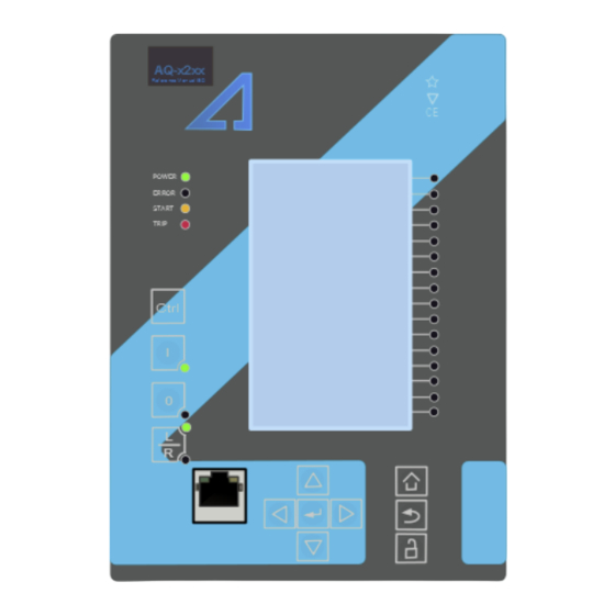
Instruction manual –AQ F215 Feeder Protection IED 11 (424 3 IED USER INTERFACE AQ 200 series IED user interface section is divided into hardware- and software user interface sections. Software interface is divided into local panel configuration and programming by using AQtivate 200 freeware software suite. - Page 12 Instruction manual –AQ F215 Feeder Protection IED 12 (424 Carousel Designer. Home button transfers the user between quick display carousel and main configuration menus. Main configuration menus are General, Protection, Control, Communication, Measurements and Monitoring. Available menus vary depending on IED type.
-
Page 13: Navigation In Main Configuration Menus
Instruction manual –AQ F215 Feeder Protection IED 13 (424 Cancel key “ ” takes you one step back or holding it down for 3 seconds takes you back to general –menu “ ”.Cancel key is also used for alarm LEDs reset. - Page 14 Instruction manual –AQ F215 Feeder Protection IED 14 (424 3.2.2.1 G ENERAL MENU General menu “ ” includes Device Info- and Function Comments sub-menus. EVICE Set name and location of the device. Serial number and SW version of the IED.
- Page 15 Instruction manual –AQ F215 Feeder Protection IED 15 (424 UNCTION OMMENTS Set specific note to protection stage or object. Note is visible under Info –menu of each stage. Figure 3.2.2.1-5 AQ-200 series IED Function Comments sub- menu.
- Page 16 Instruction manual –AQ F215 Feeder Protection IED 16 (424 3.2.2.2 P ROTECTION MENU Protection menu includes Stage activation sub-menu and sub-menus for different protection functions like Overcurrent, Earthfault, Seq. and balance and Supporting. Valid protection functions vary according IED type.
- Page 17 Instruction manual –AQ F215 Feeder Protection IED 17 (424 Activation of different protection stages is done in Stage activation –sub menu. Each protection stage and supporting function is disabled as standard. Activated menus will appear below the stage ...
- Page 18 Instruction manual –AQ F215 Feeder Protection IED 18 (424 Function is activated and disabled in Stage activation menu. It is possible to disable function in Info menu as well. Function condition indicates whether the stages condition is Normal, Start or Trip.
- Page 19 Instruction manual –AQ F215 Feeder Protection IED 19 (424 SETTINGS-menu Figure 3.2.2.2-10 All group specific settings are done individually in Settings menu. Stage settings vary according different protection functions. With factory settings only one group of eight is activated. To enable more groups go to Control menu and select Setting...
- Page 20 Instruction manual –AQ F215 Feeder Protection IED 20 (424 REGISTERS-menu Figure 3.2.2.2-11 AQ-200 series IED stage information is divided into two sections. Specific fault data of IEDs is stored in operation log under the register. Each of these 12 logs includes pre-fault current, fault current, time stamp and active group during the triggering.
- Page 21 Instruction manual –AQ F215 Feeder Protection IED 21 (424 IO-matrix Figure 3.2.2.2-12 AQ-200 series IED stage information is divided into two sections. Starting and tripping signals of protection stages are connected to physical outputs in Direct Output Control menu. It is possible to connect to output relay or to start- trip- or user configurable LED.
- Page 22 Instruction manual –AQ F215 Feeder Protection IED 22 (424 EVENTS-mask Figure 3.2.2.2-13 Protection stage related events are masked on and off individually under EventsEvent mask. Events are masked off as default. It is possible to activate desired events by masking them |x|.
- Page 23 Instruction manual –AQ F215 Feeder Protection IED 23 (424 ONTROLS NABLED Activation of different control functions is done in Controls Enabled –sub menu. Each control function is disabled as standard. Active functions will appear below Control Functions –sub menu.
- Page 24 Instruction manual –AQ F215 Feeder Protection IED 24 (424 Figure 3.2.2.3-17 Group changing with pulse control only or with pulses and static signal. BJECTS Figure 3.2.2.3-18 AQ-200 series IED object controlling. Each activated object is visible in Objects-menu. As default all objects are disabled. Each...
- Page 25 Instruction manual –AQ F215 Feeder Protection IED 25 (424 Control access may be set to Local- or Remote control (local as default). When local control is enabled it is not possible to control object trough bus and vice versa.
- Page 26 Instruction manual –AQ F215 Feeder Protection IED 26 (424 Object open- and close signals of an object are connected to physical output relays. Separate timeouts for objects are set in Settings menu. Synchronization wait- and Object Ready wait timeouts are settable between 0.02…500.00 s (default 200ms, step 20ms). If time expires the controlling of object fails.
- Page 27 Instruction manual –AQ F215 Feeder Protection IED 27 (424 trip- or user configurable LED. Connection to outputs can be either latched |x| or non-latched Object blocking is done in Blocking Input Control menu. Blocking can be done by using digital inputs, logical inputs or outputs, stage start- trip- or blocked information or by using object status information.
- Page 28 Instruction manual –AQ F215 Feeder Protection IED 28 (424 Each enabled control function is listed below Control Functions menu. Every function includes same sub-menus as protections stages including Info, Settings, Registers, IO and Events. For further information concerning these sub-menus see chapter 3.2.2.2.
- Page 29 Instruction manual –AQ F215 Feeder Protection IED 29 (424 Digital input activation and release threshold follows the measured peak value. Activation time of input is between 5-10 milliseconds. Activation delay is configurable. Release time with DC is between 5-10 milliseconds. Release time with AC is less than 25 milliseconds.
- Page 30 Instruction manual –AQ F215 Feeder Protection IED 30 (424 Figure 3.2.2.3-26 Object output- and block signal setting. LED Settings menu has two sub-menus LED Description Settings and LED Color Settings. In LED Description Settings menu the label text of the LED can be modified. This label is visible in LEDs quick displays and matrixes.
- Page 31 Instruction manual –AQ F215 Feeder Protection IED 31 (424 Figure 3.2.2.3-27 AQ-200 series IED Binary Outputs menu. Binary inputs, Logic Outputs, protection stage status signals (start, trip & blocked etc.) and object status signals can be connected to output relay or to start- trip- or user configurable LEDs in Device IO matrix ...
- Page 32 Instruction manual –AQ F215 Feeder Protection IED 32 (424 32 logical input signal status bits. Status is either 0 or 1. 32 quality bits of logical input signals (GOOSE). Status is either 0 or 1. 1 stands for bad/invalid quality.
- Page 33 Instruction manual –AQ F215 Feeder Protection IED 33 (424 CONNECTIONS-menu IP address of the IED is user settable. Default IP-address varies from device to another. Network subnet mask is entered here. Gateway is configured only when communicating with IEDs in separate subnet.
- Page 34 Instruction manual –AQ F215 Feeder Protection IED 34 (424 See more detailed information about communications options in chapter System integration. 3.2.2.5 M EASUREMENT MENU Measurement menu includes sub-menus for Transformers, Frequency, Current Measurement, Voltage measurement and Phasors depending of the IED type. Ratio of used current and voltage transformers is defined in Transformers sub-menu.
- Page 35 Instruction manual –AQ F215 Feeder Protection IED 35 (424 REQUENCY Sampling mode is fixed as standard and System nominal frequency should be set to desired level. In case the Sampling mode is set as tracking the IED will use measured frequency value as system nominal frequency.
- Page 36 Instruction manual –AQ F215 Feeder Protection IED 36 (424 Figure 3.2.2.5-35 AQ-200 series IED Sequence components. Sequence components including positive, negative and neutral components are calculated for both voltage and current. Sequence sub-menu is divided into four groups which are Per- Unit, Primary, Secondary and Phase Angle.
- Page 37 Instruction manual –AQ F215 Feeder Protection IED 37 (424 HASORS Figure 3.2.2.5-37 AQ-200 series IED Phasors sub-menu. Measurement Phasors have vector displays for voltage and currents. Also calculated components have own vector displays. Vectors can be seen in own display and additionally per unit values of measured or calculated components along with secondary and primary amplitudes are shown.
- Page 38 Instruction manual –AQ F215 Feeder Protection IED 38 (424 ONITORS NABLED Activation of different monitor functions is done in Monitors Enabled sub-menu. Each Monitoring function is disabled as standard. Activated menus will appear in the Monitor functions sub-menu.
- Page 39 Instruction manual –AQ F215 Feeder Protection IED 39 (424 ISTURBANCE Manual Trigger triggers the recording instantly once when used. It is possible to clear the latest, oldest or every stored recording at once. Maximum length of recording depends of the ...
- Page 40 Instruction manual –AQ F215 Feeder Protection IED 40 (424 EVICE IAGNOSTICS AQ-200 series IED Device Diagnostics gives detailed feedback of the IED condition generally and whether option cards are installed correctly without problems. In case anything abnormal is noticed in ...
-
Page 41: Functions Of Aq-F215 Feeder Protection Ied
Instruction manual –AQ F215 Feeder Protection IED 41 (424 AQ-F215 F UNCTIONS OF EEDER ROTECTION In this chapter are presented the functions of AQ-F215 Feeder Protection relay. AQ-F215 includes following functions and amounts of instances of the functions. Table 4-1 Protection functions of AQ-F215... -
Page 42: Measurements
Instruction manual –AQ F215 Feeder Protection IED 42 (424 NOV3 U0>>> NOV4 U0>>>> OPW1 P> Over power UPW1 P< Under power RPW1 Reverse power FRQV1 f>,f>>,f>>>,f>>>> 81O/81U Frequency protection (8 stages) f<,f<<,f<<<,f<<<< ROCOF1 df/dt >/< (1…8) Rate of change of frequency (8 stages) ARC1 IArc>/I0Arc>... - Page 43 Instruction manual –AQ F215 Feeder Protection IED 43 (424 - PRI o Primary current, the current which flows in the primary circuit and through primary side of the current transformer. - SEC o Secondary current, the current which the current transformer transforms according to its ratios.
- Page 44 Instruction manual –AQ F215 Feeder Protection IED 44 (424 current ratings are 1 and 5A. For AQ-2xx series devices also other, non-standard ratings can be directly connected since the scaling settings are flexible in large ranges. For ring core current transformers the ratings may be different. Ring core current transformers are commonly used for sensitive earth fault protection and their rated secondary may be as low as 0.2 A in some cases.
- Page 45 Instruction manual –AQ F215 Feeder Protection IED 45 (424 If the per unit scaling is wanted to be according to the CT values then “Scale meas to In” is set to “CT nom p.u.” As presented in the figure below.
- Page 46 Instruction manual –AQ F215 Feeder Protection IED 46 (424 Figure 4.1.1.1-4 Phase current transformer scalings to protected object nominal current. When measurement scaling is made to the protected object nominal current, the object nominal current needs also to be set into the “Nominal current In” input. The differences in the used scaling factors can now be seen.
- Page 47 Instruction manual –AQ F215 Feeder Protection IED 47 (424 Figure 4.1.1.1-6 Residual current I02 scaling to ring core CT input. If the scaling was made to CT primary or to object nominal current the measurements will look as follows with nominal current feeding: Figure 4.1.1.1-7 Scalings to CT nominal.
- Page 48 Instruction manual –AQ F215 Feeder Protection IED 48 (424 CT:s, if possible check the actual ratings from the CT:s as well, since in some cases the actual CT:s may have been changed from the original plan for some reason. Measured current amplitude does not match for one...
- Page 49 Instruction manual –AQ F215 Feeder Protection IED 49 (424 Phase L3 (C) polarity incorrect. Measurements: Phase currents Sequence currents IL1: 1.00 xIn / 0.00 deg I1: 0.33 xIn / 0.00 deg IL2: 1.00 xIn / 240.00 deg I2: 0.67 xIn / 60.00 deg IL3: 1.00 xIn / 300.00 deg...
- Page 50 Instruction manual –AQ F215 Feeder Protection IED 50 (424 current CT primary or protected object nominal current. Phase CT primary 1…5000.0 A 0.1A 100.0A Rated primary current of the CT in amperes. Phase CT secondary 0.2…10.0 A 0.1A 5.0A Rated secondary current of the CT in amperes.
- Page 51 Instruction manual –AQ F215 Feeder Protection IED 51 (424 I02 CT secondary 0.1…10.0 A 0.1A 5.0A Rated secondary current of the CT in amperes. I02 Polarity I02 (fine residual) measurement channel 1:Invert polarity (direction) selection. Default setting is that positive current flow is from connector 9 to connector 10.
- Page 52 Instruction manual –AQ F215 Feeder Protection IED 52 (424 Table 4.1.1.4-12 Per unit residual current measurements in AQ-2xx. Name Range Step Description Residual current I01 0.00…1250.0 xIn 0.01xIn Per unit measurement from residual current channel I01 fundamental frequency RMS current.
- Page 53 Instruction manual –AQ F215 Feeder Protection IED 53 (424 Residual current I02 0.00…300.0A 0.01A Secondary measurement from residual TRMS sec current channel I02 TRMS current including harmonics up to 31 Table 4.1.1.4-15 Residual current angles measurements in AQ-2xx. Name Range...
-
Page 54: Voltage Measurement And Scaling
Instruction manual –AQ F215 Feeder Protection IED 54 (424 Table 4.1.1.4-20 Harmonic current measurements in AQ-2xx. Name Range Step Description IL1 Harmonics 0.00…1000000.0 0.01A Per unit, primary and secondary IL1 fund…IL1 31harm harmonics per component for current input IL1 IL2 Harmonics 0.00…1000000.0... - Page 55 Instruction manual –AQ F215 Feeder Protection IED 55 (424 For the scaling the relay calculates scaling factors based into the set VT primary and secondary voltage values. Relay measures secondary voltages which in this case mean the voltage outputs from the voltage transformer that is installed into the primary circuit of the application.
- Page 56 Instruction manual –AQ F215 Feeder Protection IED 56 (424 Figure 4.1.2.1-10 Example connection with three line to neutral voltages and zero sequence voltage connected. 3LN+U4 mode has to be selected. U4 channel has to be set as U0. Initial data of the connection and the ratings are presented in following table.
- Page 57 Instruction manual –AQ F215 Feeder Protection IED 57 (424 Figure 4.1.2.1-11 Voltage may be based on line to line voltage or line to neutral voltage. This selection is completed in “Measured magnitude” –menu under each voltage protection stage separately. After the settings are input to the IED scaling factors are also calculated and displayed for the user.
- Page 58 Instruction manual –AQ F215 Feeder Protection IED 58 (424 voltage 3LN+U0. For further information see different voltage measurement mode examples below: 3LN+U4 3LL+U4 2LL+U3+U4 See below connection wirings for 3LL and 2LL connections. Figure 4.1.2.1-13 Example connections for voltage line to line measurement. Three line- to line voltages on the left and two on the right.
- Page 59 Instruction manual –AQ F215 Feeder Protection IED 59 (424 Figure 4.1.2.1-14 Two line to line measurements with zero sequence voltage and voltage from side 2 for Synchro-check 2LL+U0+SS. Line to neutral voltages can be calculated since U0 is available. In the next figure is presented relay behavior when nominal voltage is injected to the relay and the IED is measuring line to neutral voltages.
- Page 60 Instruction manual –AQ F215 Feeder Protection IED 60 (424 Figure 4.1.2.1-16 Voltage injection during earth fault to the IED by using secondary test equipment. Voltage transformer scaling is set to 20000:100 V. Voltage measurement mode is 3LN+U4 and U4 channel is measuring zero sequence voltage which has same ratio 20000:100 V.
- Page 61 Instruction manual –AQ F215 Feeder Protection IED 61 (424 4.1.2.3 S ETTINGS Table 4.1.2.3-22 Settings of the VT scaling in AQ-2xx. Name Range Step Default Description Voltage meas mode 0:3LN+U4 0:3LN+U4 Voltage wiring method to the IED. 1:3LL+U4 Voltages are scaled according the set 2:2LL+U3+U4 voltage measurement mode.
- Page 62 Instruction manual –AQ F215 Feeder Protection IED 62 (424 VT scaling factor P/S IED feedback value, this is the calculated scaling factor for primary /secondary voltage ratio VT scaling factor p.u. IED feedback value, scaling factor from p.u. value to primary voltage.
- Page 63 Instruction manual –AQ F215 Feeder Protection IED 63 (424 Table 4.1.2.4-25 Voltage phase angle measurements in AQ-2xx. Name Range Step Description Ux Angle 0.00…360.00 deg 0.01deg Phase angle measurement of the four voltage inputs. Table 4.1.2.4-26 Per unit sequence voltage measurements in AQ-2xx.
- Page 64 Instruction manual –AQ F215 Feeder Protection IED 64 (424 Table 4.1.2.4-30 Primary voltage measurements in AQ-2xx. Name Range Step Description System volt UL12 mag 0.00…1000000.00V 0.01V Primary measured or calculated fundamental frequency RMS line to line UL12 voltage. System volt UL23 mag 0.00…1000000.00V...
-
Page 65: Frequency Tracking And Sampling
Instruction manual –AQ F215 Feeder Protection IED 65 (424 Table 4.1.2.4-32 Harmonic voltage measurements in AQ-2xx. Name Range Step Description U1 Harmonics 0.00…100000.0V 0.01V Selectable per unit, primary and U1 fund…U1 31harm secondary harmonics per component for voltage input U1 U2 Harmonics 0.00…100000.0V... - Page 66 FFT calculation has always whole power cycle in the buffer. Further improvement for the achieved measurement accuracy is the Arcteq patented method of calibrating of the analog channels against 8 system frequency points for both, magnitude and angle.
- Page 67 Instruction manual –AQ F215 Feeder Protection IED 67 (424 Sampling mode 0:Fixed 0:Fixed Selection of the IED measurement 1:Tracking sampling mode either fixed user settable frequency or tracked system frequency System nominal 5…75Hz 50Hz User settable system nominal frequency frequency Tracked system 5…75.0Hz...
-
Page 68: Power And Energy Calculation
Instruction manual –AQ F215 Feeder Protection IED 68 (424 4.1.4 P OWER AND ENERGY CALCULATION AQ-2xx series IEDs with both voltage –and current cards can calculate power and have power based protection functions. When power calculation is possible also the energy magnitudes are calculated. - Page 69 Instruction manual –AQ F215 Feeder Protection IED 69 (424 Below is presented formula for three phase reactive power (Q) calculation: × I sin φ Where, × I sin φ UL1…UL3 = Line to neutral voltage × I sin φ IL1…IL3 = Phase current Q = Q φ...
- Page 70 Instruction manual –AQ F215 Feeder Protection IED 70 (424 NLY LINE TO LINE VOLTAGES AVAILABLE In case the line to line voltages are measured and zero sequence voltage is not measured and known the three phase power calculation is based on Aaron’s theorem: S = U ×...
- Page 71 Instruction manual –AQ F215 Feeder Protection IED 71 (424 Table 4.1.4.2-35 Energy Dose Counter 1 settings in AQ-2xx. Name Range Step Default Description Energy dose 0:Disabled 0:Disabled Enable energy dose counters counter mode 1:Activated generally. DC 1…4 enable 0:Disabled 0:Disabled...
- Page 72 Instruction manual –AQ F215 Feeder Protection IED 72 (424 Table 4.1.4.3-39 Phase L1 power calculation in AQ-2xx. Name Range Step Description L2 Apparent power (S) -1x10 …1x10 0.01kVA Phase L1 apparent power L2 Active power (P) -1x10 …1x10 0.01kW Phase L1 active power...
- Page 73 Instruction manual –AQ F215 Feeder Protection IED 73 (424 Table 4.1.4.4-42 Phase L1 energy calculation in AQ-2xx. Name Range Step Description L1 Exp.Active Energy Mwh -1x10 …1x10 0.01MWh Phase L1 exported active energy L1 Imp.Active Energy Mwh -1x10 …1x10 0.01MWh Phase L1 imported active energy L1 Exp/Imp.Act.E balance...
- Page 74 Instruction manual –AQ F215 Feeder Protection IED 74 (424 Table 4.1.4.4-44 Phase L3 energy calculation in AQ-2xx. Name Range Step Description L3 Exp.Active Energy Mwh -1x10 …1x10 0.01MWh Phase L3 exported active energy L3 Imp.Active Energy Mwh -1x10 …1x10 0.01MWh Phase L3 imported active energy L3 Exp/Imp.Act.E balance...
- Page 75 Instruction manual –AQ F215 Feeder Protection IED 75 (424 Name Name Name Name L1 (S) 4.08 L2 (S) 6.15 L3 (S) 9.77 3PH (S) 20.00 L1 (P) 2.89 L2 (P) 4.72 L3 (P) 9.71 3PH (P) 17.32 L1 (Q) 2.89 L2 (Q) -3.94...
-
Page 76: Protection Functions
Instruction manual –AQ F215 Feeder Protection IED 76 (424 4.2 P ROTECTION FUNCTIONS 4.2.1 G ENERAL PROPERTIES OF A PROTECTION FUNCTION In following flowchart is described the basic structure of any protection function. Basic structure is composed of the analog measurement values comparison to the pick-up values... - Page 77 Instruction manual –AQ F215 Feeder Protection IED 77 (424 Protection function is run in a completely digital environment with protection CPU microprocessor which also processes the analog signals transferred to digital form. Figure 4.2.1-18 Principle diagram of AQ-2xx protection relay platform.
- Page 78 Instruction manual –AQ F215 Feeder Protection IED 78 (424 Figure 4.2.1.1-19 Pick up and reset characteristics of the function. The pick-up activation of the function is not directly equal to start-signal generation of the function. Start signal is allowed if blocking condition is not active.
- Page 79 Instruction manual –AQ F215 Feeder Protection IED 79 (424 secondary currents from 0.001A up to 250A. To this relation the pick-up setting in secondary amperes will vary. 4.2.1.2 F UNCTION BLOCKING In the blocking element the block signal is checked in the beginning of each program cycle.
- Page 80 Instruction manual –AQ F215 Feeder Protection IED 80 (424 Name Range Step Default Description Delay Type Selection of the delay type time counter. IDMT Selection possibilities are dependent (IDMT, Inverse Definite Minimum Time) and independent (DT, Definite Time) characteristics. Definite operating 0.000…1800.000 s...
- Page 81 Instruction manual –AQ F215 Feeder Protection IED 81 (424 IEEE/ANSI ...
- Page 82 Instruction manual –AQ F215 Feeder Protection IED 82 (424 Figure 4.2.1.3-21. Definite time operating characteristics.
- Page 83 Instruction manual –AQ F215 Feeder Protection IED 83 (424 Figure 4.2.1.3-22. IEC predefined characteristics NI, VI, LTI and EI...
- Page 84 Instruction manual –AQ F215 Feeder Protection IED 84 (424 Figure 4.2.1.3-23. IEEE ANSI predefined characteristics EI, LTI, NI and VI...
- Page 85 Instruction manual –AQ F215 Feeder Protection IED 85 (424 Figure 4.2.1.3-24. IEEE predefined characteristics EI, MI and VI...
- Page 86 Instruction manual –AQ F215 Feeder Protection IED 86 (424 Figure 4.2.1.3-25. Parameters A, B and C effect to the characteristics.
- Page 87 Instruction manual –AQ F215 Feeder Protection IED 87 (424 4.2.1.4 N STANDARD DELAY CHARACTERISTICS Additionally to previously mentioned delay characteristics some functions include also delay characteristics that deviate from the norm. These functions are Overcurrent I>, Residual overcurrent Io>, Directional overcurrent Idir> and Directional residual overcurrent Iodir>...
- Page 88 Instruction manual –AQ F215 Feeder Protection IED 88 (424 Table 4-47 Reset time characteristics setting parameters. Release Time 0.000…150.000 s 0.005 s 0.06 s Resetting time. Time allowed in between delay of pick-ups if the pick-up has not lead into trip operation.
- Page 89 Instruction manual –AQ F215 Feeder Protection IED 89 (424 Figure 4.2.1.4-27. Delayed pick-up release, delay counter is reset at signal drop-off. Figure 4.2.1.4-28. Delayed pick-up release, delay counter value is held during the release time.
- Page 90 Instruction manual –AQ F215 Feeder Protection IED 90 (424 Figure 4.2.1.4-29. Delayed pick-up release, delay counter value is decreasing during the release time. Resetting characteristics can be set according to the application. Default setting is delayed with 60 ms and the time calculation is held during the release time.
-
Page 91: Non-Directional Over Current I> (50/51)
Instruction manual –AQ F215 Feeder Protection IED 91 (424 4.2.2 N I> (50/51) DIRECTIONAL OVER CURRENT Overcurrent function (NOC) is used for non-directional instant- and time delayed overcurrent/short circuit protection for various applications including feeder, filter and machine applications of utilities and industry. The number of available instances of the function depends of the IED model. - Page 92 Instruction manual –AQ F215 Feeder Protection IED 92 (424 Figure 4.2.2-30 Simplified function block diagram of the NOC function. 4.2.2.1 M EASURED INPUT VALUES Function block uses analog current measurement values. Function block always utilizes peak-to-peak measurement from samples and by user selection the monitored magnitude can be either fundamental frequency RMS values, True RMS values from the whole harmonic specter of 32 components or peak to peak values.
- Page 93 Instruction manual –AQ F215 Feeder Protection IED 93 (424 4.2.2.2 P UP CHARACTERISTICS Iset Pick-up of the NOC function is controlled by setting parameter, which defines the maximum allowed measured current before action from the function. The function constantly calculates the ratio in between of the Iset and measured magnitude (Im) per all Iset three phases.
- Page 94 Instruction manual –AQ F215 Feeder Protection IED 94 (424 4.2.2.4 O PERATING TIME CHARACTERISTICS FOR TRIP AND RESET The operating timers’ behavior of the function can be set for trip signal and also for the release of the function in case the pick-up element is reset before the trip time has been reached.
- Page 95 Instruction manual –AQ F215 Feeder Protection IED 95 (424 Delay ANSI NI Setting is active and visible when Delay characteristics ANSI VI Type is selected to IDMT. IEEE ANSI EI IEEE and ANSI standard delay ANSI LI characteristics. ANSI: Normal Inverse,...
- Page 96 Instruction manual –AQ F215 Feeder Protection IED 96 (424 When using the release delay option where the operating time counter is calculating the operating time during the release time, function will not trip if the input signal is not activated again during the release time counting.
- Page 97 Instruction manual –AQ F215 Feeder Protection IED 97 (424 Table 4.2.2.5-53. Register content. Date & Time Event Fault Trigger Fault Prefault Trip time Used code type current current current remaining dd.mm.yyyy 1280- L1-G… Start Trip Start 0 ms - 1 - 8 hh:mm:ss.mss...
-
Page 98: Non-Directional Earth Fault I0> (50N/51N)
Instruction manual –AQ F215 Feeder Protection IED 98 (424 4.2.3 N I0> (50N/51N) DIRECTIONAL EARTH FAULT Non directional earth fault function (NEF) is used for instant- and time delayed earth fault protection for various applications including feeder, filter and machine applications of utilities and industry. - Page 99 Instruction manual –AQ F215 Feeder Protection IED 99 (424 Figure 4.2.3-31 Simplified function block diagram of the NEF function. 4.2.3.1 M EASURED INPUT VALUES Function block uses analog current measurement values. Function block always utilizes peak-to-peak measurement from samples and by user selection the monitored magnitude can be either fundamental frequency RMS values, True RMS values from the whole harmonic specter of 32 components or peak to peak values.
- Page 100 Instruction manual –AQ F215 Feeder Protection IED 100 (424 4.2.3.2 P UP CHARACTERISTICS I0set Pick-up of the NEF function is controlled by setting parameter, which defines the maximum allowed measured current before action from the function. The function constantly calculates the ratio in between of the Iset and measured magnitude (Im) per all Iset three phases.
- Page 101 Instruction manual –AQ F215 Feeder Protection IED 101 (424 4.2.3.4 O PERATING TIME CHARACTERISTICS FOR TRIP AND RESET The operating timers’ behavior of the function can be set for trip signal and also for the release of the function in case the pick-up element is reset before the trip time has been reached.
- Page 102 Instruction manual –AQ F215 Feeder Protection IED 102 (424 Delay ANSI NI Setting is active and visible when Delay characteristics ANSI VI Type is selected to IDMT. IEEE ANSI EI IEEE and ANSI standard delay ANSI LI characteristics. ANSI: Normal Inverse,...
- Page 103 Instruction manual –AQ F215 Feeder Protection IED 103 (424 Table 4.2.3.4-57 Reset time characteristics setting parameters. Release Time 0.000…150.000 s 0.005 s 0.06 s Resetting time. Time allowed in between delay of pick-ups if the pick-up has not lead into trip operation.
-
Page 104: Directional Over Current Idir> (67)
Instruction manual –AQ F215 Feeder Protection IED 104 (424 Table 4.2.3.5-58. Event codes of the NEF-function instances 1 – 4. Event Event Event Event Number channel Event block name Code Description Type 1664 26 NEF1 0 Start ON 1665 26 NEF1... - Page 105 Instruction manual –AQ F215 Feeder Protection IED 105 (424 based. Monitored phase current magnitudes can be selected fundamental component RMS, TRMS values (including harmonics up to 31 ) or peak-to-peak values. Blocking signal and setting group selection controls the operating characteristics of the function during normal operation.
- Page 106 Instruction manual –AQ F215 Feeder Protection IED 106 (424 Figure 4.2.4-32 Simplified function block diagram of the DOC function. 4.2.4.1 M EASURED INPUT VALUES Function block uses analog current measurement values. Function block always utilizes peak-to-peak measurement from samples and by user selection the monitored magnitude can be either fundamental frequency RMS values, True RMS values from the whole harmonic specter of 32 components or peak to peak values.
- Page 107 Instruction manual –AQ F215 Feeder Protection IED 107 (424 Table 4.2.4.1-60 Analogic magnitudes used by the DOC function. Signal Description Time base IL1PP Peak-to-peak measurement of phase L1/A current 5 ms IL2PP Peak-to-peak measurement of phase L2/B current 5 ms...
- Page 108 Instruction manual –AQ F215 Feeder Protection IED 108 (424 Table 4.2.4.2-61 Pick-up characteristics setting Name Description Range Step Default Iset Pick-up setting 0.10 … 40.00 x In 0.01 x In 1.20 x In Angle Pick-up area ±45.0…90.0° 0.1° ±88° The pick-up activation of the function is not directly equal to start-signal generation of the function.
- Page 109 Instruction manual –AQ F215 Feeder Protection IED 109 (424 If blocking signal is active when pick-up element activates a BLOCKED signal will be generated and the function shall not process the situation further. If START function has been activated before blocking signal it will reset and the release time characteristics are processed as in case of when pick-up signal is reset.
- Page 110 Instruction manual –AQ F215 Feeder Protection IED 110 (424 When set to 0.000 s the stage operates as instant (PIOC, 50) stage without added delay. When the parameter is set to 0.005 – 1800 s the stage operates as independent delayed (PTOC, 51).
- Page 111 Instruction manual –AQ F215 Feeder Protection IED 111 (424 Release Time 0.000…150.000 s 0.005 s 0.06 s Resetting time. Time allowed in between delay of pick-ups if the pick-up has not lead into trip operation. During this time the start signal is held on for the timers if delayed pick-up release is active.
- Page 112 Instruction manual –AQ F215 Feeder Protection IED 112 (424 Table 4.2.4.5-63. Event codes of the DOC function instances 1 – 4. Event Event Event Event Alarm Number channel Event block name Code Description Type Type 4800 75 DOC1 0 Start ON...
-
Page 113: Directional Earth Fault I0Dir> (67N)
Instruction manual –AQ F215 Feeder Protection IED 113 (424 4.2.5 D > (67N) IRECTIONAL EARTH FAULT Directional earth fault function (DEF) is used for instant- and time delayed earth fault protection for various applications including feeder and machine applications of utilities and industry. - Page 114 Instruction manual –AQ F215 Feeder Protection IED 114 (424 Figure 4.2.5-34 Simplified function block diagram of the DEF function. 4.2.5.1 EASURED INPUT VALUES Function block uses analog current measurement values. Function block always utilizes peak-to-peak measurement from samples and by user selection the monitored magnitude can be either fundamental frequency RMS values, True RMS values from the whole harmonic specter of 32 components or peak to peak values.
- Page 115 Instruction manual –AQ F215 Feeder Protection IED 115 (424 Table 4.2.5.1-65 Analogic magnitudes used by the DEF function. Signal Description Time base I01PP Peak-to-peak measurement of coarse residual current 5 ms measurement input I01 I01RMS Fundamental RMS measurement of coarse residual current...
- Page 116 Instruction manual –AQ F215 Feeder Protection IED 116 (424 Table 4.2.5.2-66 Pick-up characteristics setting Name Description Range Step Default I0set Pick-up setting 0.01 … 40.00 x In 0.001 x In 1.20 x In U0set Pick-up setting 1…75 %Un 0.01 (%Un)
- Page 117 Instruction manual –AQ F215 Feeder Protection IED 117 (424 Amplitude of fault current depends of the capacitance of the network. The sources of capacitive currents are the outgoing feeders. The bigger the network the greater the capacitive current during fault is. Each outgoing feeder produces capacitance according the zero sequence capacitive reactance of the line (ohms per kilometer).
- Page 118 Instruction manual –AQ F215 Feeder Protection IED 118 (424 compensated when k-factor is greater than one and under compensated if the factor is smaller than one. Inductance connected to the star point of incoming transformer or like in most cases to grounding transformer compensates the capacitance of the network but due this the capacitive fault current cannot be measured anymore.
- Page 119 Instruction manual –AQ F215 Feeder Protection IED 119 (424 If blocking signal is active when pick-up element activates a BLOCKED signal will be generated and the function shall not process the situation further. If START function has been activated before blocking signal it will reset and the release time characteristics are processed as in case of when pick-up signal is reset.
- Page 120 Instruction manual –AQ F215 Feeder Protection IED 120 (424 When set to 0.000 s the stage operates as instant (PIOC, 50) stage without added delay. When the parameter is set to 0.005 – 1800 s the stage operates as independent delayed (PTOC, 51).
- Page 121 Instruction manual –AQ F215 Feeder Protection IED 121 (424 Table 4.2.5.4-68 Reset time characteristics setting parameters. Release Time 0.000…150.000 s 0.005 s 0.06 s Resetting time. Time allowed in between delay of pick-ups if the pick-up has not lead into trip operation.
- Page 122 Instruction manual –AQ F215 Feeder Protection IED 122 (424 Table 4.2.5.5-69. Event codes of the DEF-function instances 1 – 4. Event Event Event Event Alarm Number channel Event block name Code Description Type Type 5184 81 DEF1 0 Start ON...
-
Page 123: Intermittent Earth Fault I0Int> (67Nt)
Instruction manual –AQ F215 Feeder Protection IED 123 (424 4.2.6 I > (67NT) NTERMITTENT EARTH FAULT Intermittent earth fault is a transient type of single phase to ground fault where the actual fault phenomenon lasts about few hundred microseconds. Intermittent earth fault is commonly seen in Petersen coil grounded (compensated) medium voltage networks. - Page 124 Instruction manual –AQ F215 Feeder Protection IED 124 (424 different tools for handling than the traditional directional earth fault protection is capable of handling. Typical characteristics of intermittent earth fault include high magnitude current spikes which compared to residual voltage are in opposite direction of the current spike in the faulted feeder and same direction in non faulted feeder.
- Page 125 Instruction manual –AQ F215 Feeder Protection IED 125 (424 Figure 4.2.6-39 Close to resonance tuned network intermittent earth fault seen by healthy feeder relay. Figure 4.2.6-40 Undercompensated medium size network intermittent earth fault seen by faulty feeder relay.
- Page 126 Instruction manual –AQ F215 Feeder Protection IED 126 (424 Figure 4.2.6-41 Undercompensated medium size network intermittent earth fault seen by healthy feeder relay. As can be seen from the figures the residual voltage in both cases is high. When considering...
- Page 127 Instruction manual –AQ F215 Feeder Protection IED 127 (424 4.2.6.2 S ETTING PRINCIPLES The intermittent earth fault protection shall be coordinated with bus bar residual voltage protection in such a way that in case of intermittent earth fault the faulty feeder will be in all cases tripped by intermittent earth-fault protection function prior to residual voltage protection function considering a sufficient safety margin as well.
- Page 128 Instruction manual –AQ F215 Feeder Protection IED 128 (424 fault protection is longer than set intermittent earth fault protection operate time. It is recommended to block regular directional earth fault protection only to avoid start events of directional earth fault protection during intermittent earth faults (if start events are considered disturbing) or if directional non-intermittent earth fault protection is set to faster operate time than intermittent earth fault protection.
- Page 129 Instruction manual –AQ F215 Feeder Protection IED 129 (424 before action from the function. The function constantly calculates the ratio in between of the setting and circular buffer maximum value. Table 4.2.6.4-72 Pick-up characteristics setting Name Range Step Default Description U0 Detect spike >...
- Page 130 Instruction manual –AQ F215 Feeder Protection IED 130 (424 regardless of the measured current as long as pick-up element is active (independent time characteristics). In the following table are presented the setting parameters for the function time characteristics. Table 4.2.6.6-73 Operating time characteristics setting parameters.
- Page 131 Instruction manual –AQ F215 Feeder Protection IED 131 (424 Table 4.2.6.7-74. Event codes of the IEF function. Event Event Event Event Alarm Number channel Event block name Code Description Type Type 7296 114 IEF1 0 Start FWD ON 7297 114 IEF1...
-
Page 132: Current Unbalance I2> (46)
Instruction manual –AQ F215 Feeder Protection IED 132 (424 4.2.7 C I2> (46) URRENT UNBALANCE Current unbalance function (CUB) is used for instant- and time delayed unbalanced network protection and detection of broken conductor for various applications including feeder, filter and machine applications of utilities and industry. - Page 133 Instruction manual –AQ F215 Feeder Protection IED 133 (424 Figure 4.2.7-42 Simplified function block diagram of the CUB function. 4.2.7.1 M EASURED INPUT VALUES Function block uses analog current measurement values. Function block utilizes calculated positive and negative sequence currents. In broken conductor mode (I2/I1) also the phase currents RMS value is used for the minimum current check.
- Page 134 Instruction manual –AQ F215 Feeder Protection IED 134 (424 4.2.7.2 P UP CHARACTERISTICS I2set or I2/I1set Pick-up of the CUB function is controlled by setting parameters, which define the maximum allowed measured negative sequence current or negative/positive sequence current ratio before action from the function. The function constantly calculates the ratio in between of the Iset and measured magnitude (Im).
- Page 135 Instruction manual –AQ F215 Feeder Protection IED 135 (424 4.2.7.4 O PERATING TIME CHARACTERISTICS FOR TRIP AND RESET The operating timers’ behavior of the function can be set for trip signal and also for the release of the function in case the pick-up element is reset before the trip time has been reached.
- Page 136 Instruction manual –AQ F215 Feeder Protection IED 136 (424 Curve1 Delay curve series for IDMT operation following either IEC or IEEE/Ansi standard defined characteristics. Additionally and uniquely to I2> protection also Curve1 series is available. Delay Setting is active and visible when Delay characteristics Type is selected to IDMT.
- Page 137 Instruction manual –AQ F215 Feeder Protection IED 137 (424 Table 4.2.7.4-79 Reset time characteristics setting parameters. Release Time 0.000…150.000 s 0.005 s 0.06 s Resetting time. Time allowed in between delay of pick-ups if the pick-up has not lead into trip operation.
-
Page 138: Harmonic Over Current Ih> (50H/51H/68H)
Instruction manual –AQ F215 Feeder Protection IED 138 (424 Event Event Event Event Number channel Event block name Code Description Type 2048 32 CUB1 0 Start ON 2049 32 CUB1 1 Start OFF 2050 32 CUB1 2 Trip ON 2051... - Page 139 Instruction manual –AQ F215 Feeder Protection IED 139 (424 fundamental frequency component. Blocking signal and setting group selection controls the operating characteristics of the function during normal operation. Outputs of the function are Start Trip and Blocked signals. Setting parameters are static inputs for the function which are changed only by user input in the setup phase of the function.
- Page 140 Instruction manual –AQ F215 Feeder Protection IED 140 (424 Figure 4.2.8-43 Simplified function block diagram of the HOC function. 4.2.8.1 M EASURED INPUT VALUES Function block uses analog current measurement values from the phase currents or residual currents. For each measurement input the HOC function block utilizes the...
- Page 141 Instruction manual –AQ F215 Feeder Protection IED 141 (424 Table 4.2.8.1-82 Analogic magnitudes used by the HOC function. Signal Description Time base IL1FFT Magnitudes (rms) of phase L1/A current components: 5 ms Fundamental, 2 harmonic, 3 harmonic, 4 harmonic, 5...
- Page 142 Instruction manual –AQ F215 Feeder Protection IED 142 (424 Table 4.2.8.2-83 Operating mode selection settings of the HOC function Name Range Step Default Description Harmonic harmonic harmonic Selection of the monitored harmonic selection harmonic component harmonic harmonic harmonic harmonic harmonic...
- Page 143 Instruction manual –AQ F215 Feeder Protection IED 143 (424 4.2.8.4 F UNCTION BLOCKING In the blocking element the block signal is checked in the beginning of each program cycle. Blocking signal is received from the blocking matrix for the function dedicated input. If the blocking signal is not activated when the pick-up element activates, a START signal is generated and the function proceeds to the time characteristics calculation.
- Page 144 Instruction manual –AQ F215 Feeder Protection IED 144 (424 Table 4.2.8.5-85 Operating time characteristics setting parameters. Name Range Step Default Description Delay Type Selection of the delay type time counter. IDMT Selection possibilities are dependent (IDMT, Inverse Definite Minimum Time) and independent (DT, Definite Time) characteristics.
- Page 145 Instruction manual –AQ F215 Feeder Protection IED 145 (424 Table 4.2.8.5-86 Reset time characteristics setting parameters. Release Time 0.000…150.000 s 0.005 s 0.06 s Resetting time. Time allowed in between delay of pick-ups if the pick-up has not lead into trip operation.
- Page 146 Instruction manual –AQ F215 Feeder Protection IED 146 (424 Table 4.2.8.6-87. Event codes of the HOC function instances 1 – 4. Event Event Event Event Number channel Event block name Code Description Type 2368 37 HOC1 0 Start ON 2369...
-
Page 147: Circuit Breaker Failure Protection (Cbfp) (50Bf)
Instruction manual –AQ F215 Feeder Protection IED 147 (424 4.2.9 C (CBFP) (50BF) IRCUIT BREAKER FAILURE PROTECTION Circuit breaker failure protection (CBFP) function is used for monitoring the circuit breaker operation after it has been tripped. CBFP function can be used for Retrip to the failing breaker and if the Retrip fails the upstream breaker can be tripped by using CBFP output. - Page 148 Instruction manual –AQ F215 Feeder Protection IED 148 (424 Figure 4.2.9-44 Simplified function block diagram of the CBFP function. 4.2.9.1 M EASURED INPUT VALUES Function block uses analog current measurement values. Function uses always the fundamental frequency magnitude of the current measurement input. For residual current measurement I01, I02 or calculated I0 can be selected.
- Page 149 Instruction manual –AQ F215 Feeder Protection IED 149 (424 Table 4.2.9.1-90 Operating mode and input signals selection Name Range Step Default Description I0Input Selection of the residual current monitoring from the two separate residual I0Calc measurements I01 and I02 or from phase currents calculated residual current.
- Page 150 Instruction manual –AQ F215 Feeder Protection IED 150 (424 If blocking signal is active when pick-up element activates a BLOCKED signal will be generated and the function shall not process the situation further. If START function has been activated before blocking signal it will reset and the release time characteristics are processed as in case of when pick-up signal is reset.
- Page 151 Instruction manual –AQ F215 Feeder Protection IED 151 (424 Figure 4.2.9.4-45 Into the IED is configured Trip, Retrip and CBFP. In application where the circuit breaker has retrip / redundant trip coil available, retrip functionality can be used. The trip signal is wired normally to the trip coil of the breaker from the trip output of the IED.
- Page 152 Instruction manual –AQ F215 Feeder Protection IED 152 (424 Figure 4.2.9.4-46 Retrip and CBFP when selected criteria is current only. In case when the current based protection activates so that either Iset and/or I0Sset current threshold setting is exceeded the counters for retrip and CBFP start to calculate the set operating time.
- Page 153 Instruction manual –AQ F215 Feeder Protection IED 153 (424 the monitored output contact is controlled (primary protection operates). From the tripping signal of the primary protection stage the counters for retrip and CBFP start to calculate the set operating time. The tripping of the primary protection stage is constantly monitored...
- Page 154 Instruction manual –AQ F215 Feeder Protection IED 154 (424 current based functions with added security from the current monitoring of the CBFP function and other function trips can be also included to the CBFP functionality. Figure 4.2.9.4-49 Into the IED is configured Trip and CBFP.
- Page 155 Instruction manual –AQ F215 Feeder Protection IED 155 (424 Figure 4.2.9.4-50 CBFP when selected criteria is current only. In case when the current based protection activates so that either Iset and/or I0Sset current threshold setting is exceeded, the counter for CBFP start to calculate the set operating time.
- Page 156 Instruction manual –AQ F215 Feeder Protection IED 156 (424 In case when the current based protection activates so that either Iset and/or I0Sset current threshold setting are exceeded the counter for CBFP is halted until the monitored output contact is controlled (primary protection operates). From the tripping signal of the primary protection stage the counter for CBFP start to calculate the set operating time.
- Page 157 Instruction manual –AQ F215 Feeder Protection IED 157 (424 Figure 4.2.9.4-53 IED is configured as dedicated CBFP unit. In some applications dedicated circuit breaker protection unit is required. When the CBFP function is configured to operate with DI signal it can be used in these applications. When the IED is used for this purpose the tripping signal is wired to the IED digital input and the IED:s own trip signal is used for CBFP purpose only.
- Page 158 Instruction manual –AQ F215 Feeder Protection IED 158 (424 Figure 4.2.9.4-54 Dedicated CBFP operation from binary input signal. In this mode the CBFP operates from binary input signal only. Additionally also current and output relay monitoring can be used. The counter for the CBFP is started when the digital input is activated.
- Page 159 Instruction manual –AQ F215 Feeder Protection IED 159 (424 Table 4.2.9.5-93. Event codes of the CBFP function instance Event Event Event Event Number channel Event block name Code Description Type 2817 44 CBF1 1 Start ON 2818 44 CBF1 2 Start OFF...
-
Page 160: Restricted Earth Fault / Cable End Differential (Ref) I0D> (87N)
Instruction manual –AQ F215 Feeder Protection IED 160 (424 4.2.10 R (REF) I0D> (87N) ESTRICTED EARTH FAULT CABLE END DIFFERENTIAL Restricted Earth Fault function (REF) is used for residual differential current measurement for transformers and also this function can be used for Cable End Differential (CED) functionality. - Page 161 Instruction manual –AQ F215 Feeder Protection IED 161 (424 Figure 4.2.10-55 Simplified function block diagram of the REF function. 4.2.10.1 M EASURED INPUT VALUES Function block uses analog current measurement values. Function uses the fundamental frequency magnitude of the current measurement inputs and calculated residual current with residual current measurement.
- Page 162 Instruction manual –AQ F215 Feeder Protection IED 162 (424 Table 4.2.10.1-96 General settings of the REF stage (not SG selectable) Name Range Step Default Description I0d> mode 0: Disabled Disabled Selection of the function is activated or 1: Activated disabled in the configuration. Default setting 0: Disabled (Not in use).
- Page 163 Instruction manual –AQ F215 Feeder Protection IED 163 (424 The pick-up activation of the function is not directly equal to trip-signal generation of the function. Trip signal is allowed if blocking condition is not active. In the following figure is presented the differential characteristics with default settings.
- Page 164 Instruction manual –AQ F215 Feeder Protection IED 164 (424 Characteristics settings are calculated as follows: Diff Bias<TP1 0d>Pick-up = SL1 × ( TP2-TP1 ) + I Diff Bias TP1…TP2 0d>Pick-up = SL2 × ( Ix-TP2 ) + SL1 × ( TP2-TP1 ) + I Diff Bias>TP2...
- Page 165 Instruction manual –AQ F215 Feeder Protection IED 165 (424 Characteristics Differential characteristics DIFF 2.00 1.00 0.00 I Bias Figure 4.2.10.3-57 Cable end differential with natural unbalance in the phase current measurement. When calculating the residual current from phase currents the natural unbalance may be in total around 10% and still the used CT:s are in the promised 5P class (probably most common CT accuracy class).
- Page 166 Instruction manual –AQ F215 Feeder Protection IED 166 (424 earth faults. For this purpose restricted earth fault function is stabile since it monitors only the side it is wired to and compares the calculated and measured residual currents. In case...
- Page 167 Instruction manual –AQ F215 Feeder Protection IED 167 (424 4.2.10.4 E VENTS AND REGISTERS The REF function generates events and registers from the status changes of the Trip activated and blocked signals. To main event buffer is possible to select status “On” or “Off”...
-
Page 168: Thermal Overload Protection For Feeders T > (49F)
Instruction manual –AQ F215 Feeder Protection IED 168 (424 4.2.11 T > (49F) HERMAL OVERLOAD PROTECTION FOR FEEDERS Thermal overload function for feeder (TOLF) is used for cables and overhead lines thermal capacity monitoring and protection. Also this function can be used for any single time constant application like inductor chokes, certain types of transformers and any other static units which don’t have active cooling in addition to the cables and overhead lines. - Page 169 Instruction manual –AQ F215 Feeder Protection IED 169 (424 its heating constant tau (), 63% of the nominal thermal capacity is used. When the loading continues until five times this given constant the used thermal capacity indefinitely approaches to 100% but never exceeds it. With a single time constant model cooling of the object follows this same behavior reversible to the heating when the current feeding is completely zero.
- Page 170 Instruction manual –AQ F215 Feeder Protection IED 170 (424 temperature. The calculated coefficient is linear correction factor which is presented with following formulas: Amb<t × ( t ) ) + k Amb<t × ( t ) ) + 1.0 Amb>t Amb>t...
- Page 171 Instruction manual –AQ F215 Feeder Protection IED 171 (424 This mentioned ambient temperature coefficient relates to nominal temperature reference. By default is used +15 C (ground dug cables) which gives coefficient value of 1.00 for the thermal replica. Settable thermal capacity curve uses linear interpolation for ambient temperature correction with maximum 10 pairs of temperature –...
- Page 172 Instruction manual –AQ F215 Feeder Protection IED 172 (424 The correction coefficient curve for ambient temperature is shown in the figure. The reference temperature for ground dug cables usually is 15 ̊ C which gives correction coefficient of 1.00 which...
- Page 173 Instruction manual –AQ F215 Feeder Protection IED 173 (424 Figure 4.2.11-66 Initial data of the cable temperature characteristics and current ratings with different installations and copper or aluminium conductors. Based into the given data can be seen the currents which in given installation and construction methods will achieve the given temperature in given standard conditions.
- Page 174 Instruction manual –AQ F215 Feeder Protection IED 174 (424 Figure 4.2.11-67 General presumptions of the high voltage cables. If the installation conditions vary from the presumption conditions, manufacturers may give additional information of how the current carrying capacity should be corrected in order to...
- Page 175 Instruction manual –AQ F215 Feeder Protection IED 175 (424 Figure 4.2.11-68 Correction coefficients for the current carrying capacity given by the manufacturer (Prysmian). As an example of the k (service factor, current carrying capacity) factor importance let’s calculate cable installation with correct k factor and without setting it to correct value.
- Page 176 Instruction manual –AQ F215 Feeder Protection IED 176 (424 Initial data for the set-up of the thermal image: 500 mm cross sectional 66 kV copper cable is installed into ground. Its 1s permissible short circuit current is 71.4 kA and its insulation is XLPE. The cables screen circuit is open and the laying of the cable is flat.
- Page 177 Instruction manual –AQ F215 Feeder Protection IED 177 (424 With maximum allowed load the end temperature 89 ̊ C has been reached with thermal capacity 99.6% used. From this result can be noted that thermal image matches perfectly into the expectations.
- Page 178 Instruction manual –AQ F215 Feeder Protection IED 178 (424 so the settings would be then In = 680 A, Tmax = 90 ̊ C , Tamb = 15 ̊ C , Tref = 15 ̊ C and = 0.81 Now when trying to load the...
- Page 179 Instruction manual –AQ F215 Feeder Protection IED 179 (424 4.2.11.1 T HERMAL OVERLOAD FUNCTION Blocking signal and setting group selection controls the operating characteristics of the function during normal operation. Outputs of the function are TOLF Trip and Blocked signals. Setting parameters are static inputs for the function which are changed only by user input in the setup phase of the function.
- Page 180 Instruction manual –AQ F215 Feeder Protection IED 180 (424 Function block uses analog current measurement values. Function uses the fundamental frequency magnitude of the current measurement inputs and calculated residual current with residual current measurement. For residual current measurement I01 or I02 can be selected.
- Page 181 Instruction manual –AQ F215 Feeder Protection IED 181 (424 visible if Set or estimate tau setting is selected to “Estimate”. Rated nominal current 1…1000000 A 700 A Rated nominal current in primary value of the protected object in nominal rated conditions. Setting is visible if Set or estimate tau setting is selected to “Estimate”.
- Page 182 Instruction manual –AQ F215 Feeder Protection IED 182 (424 Table 4.2.11.2-103 Environmental settings Name Range Step Default Description Object max temp (tmax = 0…500 deg 1 deg Maximum allowed temperature for 100%) the protected object. Default setting is +90 degrees and it suits for...
- Page 183 Instruction manual –AQ F215 Feeder Protection IED 183 (424 setting. Setting is visible if Ambient lin. or curve is set to “Linear est.” Amb.Temp.ref1...10 -50.0…500.0 0.1 deg 15 deg Temperature reference points for the user settable ambient temperature coefficient curve.
- Page 184 Instruction manual –AQ F215 Feeder Protection IED 184 (424 time. Default setting is 0.000s which will not give added time delay for the trip signal. The pick-up activation of the IO is direct for all other signals except TRIP signal which has also blocking check before the trip signal is generated.
- Page 185 Instruction manual –AQ F215 Feeder Protection IED 185 (424 xIn status “Overloading” will be shown and when measured current is over 2 xIn status “High overload” will be shown. Table 4.2.11.5-106 Measurements Name Range Description / values Currents 0: Primary A...
-
Page 186: Over Voltage U> (59)
Instruction manual –AQ F215 Feeder Protection IED 186 (424 In the function is available 12 last registers where the triggering event of the function (Trip activated or blocked) is recorded with time stamp and process data values. Table 4.2.11.6-108. Event codes of the TOLF function instance... - Page 187 Instruction manual –AQ F215 Feeder Protection IED 187 (424 Outputs of the function are Start Trip and Blocked signals. Setting parameters are static inputs for the function which are changed only by user input in the setup phase of the function.
- Page 188 Instruction manual –AQ F215 Feeder Protection IED 188 (424 Table 4-110 Analogic magnitudes used by the OV function. Signal Description Time base Fundamental RMS measurement of voltage U 5 ms Fundamental RMS measurement of voltage U 5 ms Fundamental RMS measurement of voltage U...
- Page 189 Instruction manual –AQ F215 Feeder Protection IED 189 (424 4.2.12.3 F UNCTION BLOCKING In the blocking element the block signal is checked in the beginning of each program cycle. Blocking signal is received from the blocking matrix for the function dedicated input. If the blocking signal is not activated when the pick-up element activates, a START signal is generated and the function proceeds to the time characteristics calculation.
- Page 190 Instruction manual –AQ F215 Feeder Protection IED 190 (424 Table 4-113 Operating time characteristics setting parameters. Name Range Step Default Description Delay Type Selection of the delay type time counter. IDMT Selection possibilities are dependent (IDMT, Inverse Definite Minimum Time) and independent (DT, Definite Time) characteristics.
- Page 191 Instruction manual –AQ F215 Feeder Protection IED 191 (424 When using the release delay option where the operating time counter is calculating the operating time during the release time, function will not trip if the input signal is not activated again during the release time counting.
- Page 192 Instruction manual –AQ F215 Feeder Protection IED 192 (424 Table 4-116. Register content. Date & Time Event Fault Trigger Fault Prefault Trip time Used code type voltage voltage voltage remaining dd.mm.yyyy 5440- L1-… Start Trip Start 0 ms - 1 - 8 hh:mm:ss.mss...
-
Page 193: Under Voltage U< (27)
Instruction manual –AQ F215 Feeder Protection IED 193 (424 4.2.13 U U< (27) NDER VOLTAGE Undervoltage function (UV) is used for instant- and time delayed undervoltage protection for various applications including feeder, filter and machine applications of utilities and industry. Each IED with voltage protection module has four available instances of the function (U<, U<<, U<<<, U<<<<). - Page 194 Instruction manual –AQ F215 Feeder Protection IED 194 (424 Figure 4.2.13-75 Simplified function block diagram of the UV function. 4.2.13.1 M EASURED INPUT VALUES Analog voltage measurement values are used for the function block. Function block utilizes always peak-to-peak measurement from samples and by user selection the monitored magnitude can be either fundamental frequency RMS values, True RMS values from the whole harmonic specter of 32 components or peak to peak values.
- Page 195 Instruction manual –AQ F215 Feeder Protection IED 195 (424 calculates the ratio in between of the Uset and measured magnitude (Um) per all three Uset voltages. Reset ratio of 103 % is inbuilt in the function and is always related to the value.
- Page 196 Instruction manual –AQ F215 Feeder Protection IED 196 (424 reached. There are three basic operating modes available for the function. Instant operation gives the trip signal with no additional time delay simultaneously with start signal. Definite time operation (DT) will give trip signal with user given time delay regardless of the measured voltage as long as the voltage is below the Uset value and thus pick-up element is active (independent time characteristics).
- Page 197 Instruction manual –AQ F215 Feeder Protection IED 197 (424 Table 4.2.13.4-120 Reset time characteristics setting parameters. Release Time 0.000…150.000 s 0.005 s 0.06 s Resetting time. Time allowed in between delay of pick-ups if the pick-up has not lead into trip operation.
- Page 198 Instruction manual –AQ F215 Feeder Protection IED 198 (424 4.2.13.5 E VENTS AND REGISTERS The UV function generates events and registers from the status changes of start, trip and blocked. To main event buffer is possible to select status “On” or “Off” messages. The UV function offers four independent instances which events are segregated for each instance operation.
-
Page 199: Sequence Voltage U1/U2>/< (59P/27P/47)
Instruction manual –AQ F215 Feeder Protection IED 199 (424 4.2.14 S U1/U2>/< (59P/27P/47) EQUENCE VOLTAGE Sequence voltage function (VUB) is used for instant- and time delayed voltage protection for various feeder, machine, utility and industry applications. It is has positive- and negative sequence over- and under voltage protection built in. - Page 200 Instruction manual –AQ F215 Feeder Protection IED 200 (424 See positive sequence calculation examples below. Swapped Swapped Vector 120 degrees 240 degrees divided by three Normal situation. Vector Swapped Swapped 120 degrees 240 degrees divided by three Earth fault in isolated network.
- Page 201 Instruction manual –AQ F215 Feeder Protection IED 201 (424 = Line to neutral voltages L1…3 See negative sequence calculation examples below. Figure 4.2.14-77 Negative sequence component vector examples. Outputs of the function are Start Trip and Blocked signals. Blocking can be executed by using external block signal or by using low voltage block function integrated to the stage.
- Page 202 Instruction manual –AQ F215 Feeder Protection IED 202 (424 The operational logic consists of input magnitude processing, input magnitude selection, threshold comparator, block signal check, time delay characteristics and output processing. Inputs for the function are the operating mode selections, setting parameters and measured and pre-processed voltage magnitudes and binary input signals.
- Page 203 Instruction manual –AQ F215 Feeder Protection IED 203 (424 4.2.14.4 P UP CHARACTERISTICS Uset Pick-up of the VUB function is controlled by setting parameter, which defines the maximum or minimum allowed calculated U1 or U2 voltage before action from the function.
- Page 204 Instruction manual –AQ F215 Feeder Protection IED 204 (424 4.2.14.6 O PERATING TIME CHARACTERISTICS FOR TRIP AND RESET The operating timers’ behavior of the function can be set for trip signal and also for the release of the function in case the pick-up element is reset before the trip time has been reached.
- Page 205 Instruction manual –AQ F215 Feeder Protection IED 205 (424 Table 4.2.14.6-126 Reset time characteristics setting parameters. Release Time 0.000…150.000 s 0.005 s 0.06 s Resetting time. Time allowed in between delay of pick-ups if the pick-up has not lead into trip operation.
- Page 206 Instruction manual –AQ F215 Feeder Protection IED 206 (424 Table 4.2.14.7-127. Event codes of the VUB function instance 1 – 4. Event Event Event Event Alarm Number channel Event block name Code Description Type Type 8320 130 VUB1 0 Start ON...
-
Page 207: Neutral Voltage U0> (59N)
Instruction manual –AQ F215 Feeder Protection IED 207 (424 4.2.15 N U0> (59N) EUTRAL VOLTAGE Neutral overvoltage function (NOV) is used for non-directional instant- and time delayed earth fault protection for various applications including feeder, filter and machine applications of utilities and industry. Each IED with voltage protection module has four available instances of the function (U0>, U0>>, U0>>>, U0>>>>). - Page 208 Instruction manual –AQ F215 Feeder Protection IED 208 (424 See zero sequence calculation examples below. Vector divided by three Normal situation. Vector divided by three Earth fault in isolated network. Vector divided by three Close distance short circuit between phases 1 and 3.
- Page 209 Instruction manual –AQ F215 Feeder Protection IED 209 (424 Figure 4.2.15-80 Measured neutral voltage example. For monitored voltage magnitudes can be selected fundamental component RMS and TRMS values (including harmonics up to 31 ). Blocking signal and setting group selection controls the operating characteristics of the function during normal operation.
- Page 210 Instruction manual –AQ F215 Feeder Protection IED 210 (424 Figure 4.2.15-81 Simplified function block diagram of the NOV function. 4.2.15.1 M EASURED INPUT VALUES Function block uses the analog voltage measurement values. Function block utilizes either fundamental frequency RMS values or True RMS values from the whole harmonic specter of 32 components.
- Page 211 Instruction manual –AQ F215 Feeder Protection IED 211 (424 Table 4.2.15.2-130 Pick-up characteristics setting Name Description Range Step Default Uset Pick-up setting 1.00 … 100.00 % Un 0.1 V 20 % Un The pick-up activation of the function is not directly equal to start-signal generation of the function.
- Page 212 Instruction manual –AQ F215 Feeder Protection IED 212 (424 measured voltage Um (dependent time characteristics). For the IDMT operation is available IEC and IEEE/ANSI standard characteristics as well as user settable parameters. In the following table are presented the setting parameters for the function time characteristics.
- Page 213 Instruction manual –AQ F215 Feeder Protection IED 213 (424 Resetting characteristics can be set according to the application. Default setting is delayed with 60 ms and the time calculation is held during the release time. When using the release delay option where the operating time counter is calculating the operating time during the release time, function will not trip if the input signal is not activated again during the release time counting.
- Page 214 Instruction manual –AQ F215 Feeder Protection IED 214 (424 Table 4.2.15.5-134. Register content. Date & Time Event Fault Trigger Fault Prefault Trip time Used code type voltage voltage voltage remaining dd.mm.yyyy 5952- L1-G… Start Trip Start 0 ms - 1 - 8 hh:mm:ss.mss...
-
Page 215: Over- And Under Frequency F>/< (81O/81U)
Instruction manual –AQ F215 Feeder Protection IED 215 (424 4.2.16 O >/< (81O/81U) AND UNDER FREQUENCY F Frequency protection function can be used for both under frequency and over frequency situations and it has four stages for both. Frequency protection can be applied to protect feeder, bus, transformer, motor and generator applications. - Page 216 Instruction manual –AQ F215 Feeder Protection IED 216 (424 is 1ms. Function provides also cumulative counters for START, TRIP and BLOCKED events. In the following figure is presented the simplified function block diagram of the FRQV function. Figure 4.2.16-82 Simplified function block diagram of the FRQV function.
- Page 217 Instruction manual –AQ F215 Feeder Protection IED 217 (424 4.2.16.2 P UP CHARACTERISTICS AND TIME DELAY fset>, fset>> Pick-up of each stage of FRQV functions stage is controlled by etc. setting parameter, which defines the maximum or minimum allowed measured frequency before action from the function.
- Page 218 Instruction manual –AQ F215 Feeder Protection IED 218 (424 blocking signal is not activated when the pick-up element activates, a START signal is generated and the function proceeds to the time characteristics calculation. If blocking signal is active when pick-up element activates a BLOCKED signal will be generated and the function shall not process the situation further.
- Page 219 Instruction manual –AQ F215 Feeder Protection IED 219 (424 Table 4.2.16.4-138. Event codes of the FRQV function. Event Event Event Event Alarm Number channel Event block name Code Description Type Type 6336 99 FRQV1 0 f> Start ON 6337 99 FRQV1 1 f>...
-
Page 220: Rate-Of-Change Of Frequency Protection Df/Dt (81R)
Instruction manual –AQ F215 Feeder Protection IED 220 (424 Table 4.2.16.4-139. Register content. Date & Time Event f Pretrig (Hz) f Fault (Hz) Setting group in code dd.mm.yyyy 6336- Start –20ms Fault frequency Starts used at the hh:mm:ss.mss 6383 averages triggering moment Descr. - Page 221 Instruction manual –AQ F215 Feeder Protection IED 221 (424 In the figure above is presented an example case of df/dt function operation when the frequency is decreasing. If the f is activated df/dt doesn’t trip no matter how fast the limit measured frequency changes if it’s over the f...
- Page 222 Instruction manual –AQ F215 Feeder Protection IED 222 (424 Figure 4.2.17-83 Simplified function block diagram of the ROCOF function. 4.2.17.1 M EASURED INPUT VALUES Rate of change of frequency protection function compares measured df/dt to pick-up setting given in Hz/s. Source of measured frequency depends on the factory defined tracking reference which can be checked from frequency tab behind measurements-menu.
- Page 223 Instruction manual –AQ F215 Feeder Protection IED 223 (424 Table 4.2.17.2-141 Pick-up characteristics setting Name Description Range Step Default df/dt>/<(1…8)pick-up Pick-up setting 0.01 … 10.00 0.01Hz/s 0.2 Hz/s df/dt>/<(1…8) f< limit f< limit 7.00…65.00 0.01Hz/s 49.95 Hz/s df/dt>/<(1…8) f> limit f>...
- Page 224 Instruction manual –AQ F215 Feeder Protection IED 224 (424 Blocking signal can be tested also in the commissioning phase of the stage by software switch signal when relay common and global testing mode is activated. User settable variables are binary signals from the system. Blocking signal needs to reach the IED minimum of 5 ms before the set operating delay has passed for blocking to be active in time.
- Page 225 Instruction manual –AQ F215 Feeder Protection IED 225 (424 Table 4.2.17.4-143. Event codes of the ROCOF function. Event Event Event Event Alarm Number channel Event block name Code Description Type Type 6592 103 DFT1 0 df/dt </> (1) Start ON...
-
Page 226: Over Power P> (32O)
Instruction manual –AQ F215 Feeder Protection IED 226 (424 4.2.18 O P> (32O) VER POWER AQ-2xx series IEDs with both voltage –and current cards can have over power function (POW), which is used for instant- and time delayed active over power protection. In applications like feeder-, generator- and motor protection it is used to detect overload situations by measuring three phase active power. - Page 227 Instruction manual –AQ F215 Feeder Protection IED 227 (424 each of the three output signal. In instant operating mode the function outputs START and TRIP events simultaneously with equivalent time stamp. Time stamp resolution is 1ms. Function provides also cumulative counters for START, TRIP and BLOCKED events.
- Page 228 Instruction manual –AQ F215 Feeder Protection IED 228 (424 Table 4.2.18.2-146 Pick-up characteristics setting Name Description Range Step Default Pset> Pick-up setting 0.0 … 100000 kW 0.01 kV 100 kW The pick-up activation of the function is not directly equal to start-signal generation of the function.
- Page 229 Instruction manual –AQ F215 Feeder Protection IED 229 (424 Table 4.2.18.4-147 Operating time characteristics setting parameters. Name Range Step Default Description Definite operating 0.000…1800.000 s 0.005 s 0.040 s Definite time operating delay. When set to time delay 0.000 s the stage operates as instant (PIOC, 50) stage without added delay.
-
Page 230: Under Power P< (32U)
Instruction manual –AQ F215 Feeder Protection IED 230 (424 In the function is available 12 last registers where the triggering event of the function (start, trip or blocked) is recorded with time stamp and process data values. Table 4.2.18.5-149. Event codes of the OPW function. - Page 231 Instruction manual –AQ F215 Feeder Protection IED 231 (424 Below is presented formula for three phase active power (P) calculation when line-to-neutral voltages are available: Where, × I cos φ UL1…UL3 = Line to neutral voltage × I cos φ...
- Page 232 Instruction manual –AQ F215 Feeder Protection IED 232 (424 Figure 4.2.19-85 Simplified function block diagram of the UPW function. 4.2.19.1 M EASURED INPUT VALUES Three phase active power value is used for the function block. -20ms averaged value is used for pre-fault data registering.
- Page 233 Instruction manual –AQ F215 Feeder Protection IED 233 (424 Figure 4.2.19-86 Activation and deactivation characteristics of the Under Power functions Low Power Blocking. To prevent accidental tripping before active power exceeds under powers pick-up setting, low power block-setting can be used. LPB-signal deactivates when measured active power exceeds pick-up settings reset value (1.03xPset).
- Page 234 Instruction manual –AQ F215 Feeder Protection IED 234 (424 If blocking signal is active when pick-up element activates a BLOCKED signal will be generated and the function shall not process the situation further. If START function has been activated before blocking signal it will reset and the release time characteristics are processed as in case of when pick-up signal is reset.
- Page 235 Instruction manual –AQ F215 Feeder Protection IED 235 (424 Table 4.2.19.4-154 Reset time characteristics setting parameters. Release Time 0.000…150.000 s 0.005 s 0.06 s Resetting time. Time allowed in between delay of pick-ups if the pick-up has not lead into trip operation.
-
Page 236: Reverse Power Pr (32R)
Instruction manual –AQ F215 Feeder Protection IED 236 (424 In the register of the UPW function is recorded start, trip or blocked “On” event process data. In the table below is presented the structure of UPW function register content. This information is available in 12 last recorded events for all provided instances separately. - Page 237 Instruction manual –AQ F215 Feeder Protection IED 237 (424 The function can operate on instant or time delayed mode. The operational logic consists of input magnitude processing, threshold comparator, two block signal check, time delay characteristics and output processing. Inputs for the function are the operating mode selections, setting parameters and measured and pre-processed power magnitudes and binary input signals.
- Page 238 Instruction manual –AQ F215 Feeder Protection IED 238 (424 4.2.20.2 P UP CHARACTERISTICS Pset rev. Pick-up of the RPW function is controlled by setting parameter, which defines the maximum allowed measured three phase active power before action from the function. The function constantly calculates the ratio in between of the Pset rev.
- Page 239 Instruction manual –AQ F215 Feeder Protection IED 239 (424 4.2.20.4 O PERATING TIME CHARACTERISTICS FOR TRIP AND RESET The operating timers’ behavior of the function can be set for trip signal and also for the release of the function in case the pick-up element is reset before the trip time has been reached.
-
Page 240: Arc Fault Protection Iarc>/I0Arc>(50Arc/50Narc)
Instruction manual –AQ F215 Feeder Protection IED 240 (424 When using the release delay option where the operating time counter is calculating the operating time during the release time, function will not trip if the input signal is not activated again during the release time counting. - Page 241 Instruction manual –AQ F215 Feeder Protection IED 241 (424 protection relay controlling the feeder breakers operation time could be necessary to delay for hundreds of milliseconds after sensing the fault to achieve selectivity. This delay can be avoided by using arc protection. To extent the speed of arc protection operation arc protection card has high speed output as well to give tripping signal faster.
- Page 242 Instruction manual –AQ F215 Feeder Protection IED 242 (424 Table 4.2.20.5-163 Output signals of the arc protection function Outputs Channel1 Light In Channel2 Light In Channel3 Light In Channel4 Light In Channel1 Pressure In Channel2 Pressure In Channel3 Pressure In...
- Page 243 Instruction manual –AQ F215 Feeder Protection IED 243 (424 Figure 4.2.21-88 Scheme IA1 single-line diagram with AQ-2xx series relays and AQ-101 arc protection relays. To set the zones for the AQ-2xx models sensor channels start by enabling the protected zones which in this case are Zones 1 and 2. Then define which sensor channels are sensing which zones.
- Page 244 Instruction manual –AQ F215 Feeder Protection IED 244 (424 Figure 4.2.21-89 Scheme IA1 single-line diagram with AQ-2xx series relays. The relay supervising the incoming feeder settings are the same as in the first example. The relays supervising the busbar and the outgoing feeder should be set up in the following way.
- Page 245 Instruction manual –AQ F215 Feeder Protection IED 245 (424 4.2.21.2 M EASURED INPUT VALUES Arc protection uses sample based per phase measurement. If required number of samples is found over the setting limit current condition activates. It is possible to use either phase currents or residual current in the tripping decision.
- Page 246 Instruction manual –AQ F215 Feeder Protection IED 246 (424 If blocking signal is active when pick-up element activates a BLOCKED signal will be generated and the function shall not process the situation further. If TRIP function has been activated before blocking signal it will reset and the release time characteristics are processed as in case of when pick-up signal is reset.
- Page 247 Instruction manual –AQ F215 Feeder Protection IED 247 (424 Table 4.2.21.5-165. Event codes of the ARC function. Event Event Event Event Alarm Number channel Event block name Code Description Type Type 4736 74 ARC1 0 Zone1 Trip On 4737 74 ARC1...
-
Page 248: Control Functions
Instruction manual –AQ F215 Feeder Protection IED 248 (424 4.3 C ONTROL FUNCTIONS 4.3.1 S (SGS) ETTING GROUP SELECTION Eight (8) separate setting groups are available in in AQ-2xx series devices. Availability and selection is controlled by SGS function block. By default only SG1 is active and thus the selection logic is idle. - Page 249 Instruction manual –AQ F215 Feeder Protection IED 249 (424 For the application controlled setting group switch and selection is available either pulse controlled change or signal level change options. In the setting group controller block is prioritized the setting groups so that if higher one is controlled simultaneously with lower priority setting group the higher request shall be taken into use.
- Page 250 Instruction manual –AQ F215 Feeder Protection IED 250 (424 Table 4.3.1.1-167 Settings of the SGS function. Name Range Step Default Description Used setting 0=SG1 Selection of activated setting groups in groups 1=SG1...2 the application. If setting group is enabled 2=SG1...3 it cannot be controlled to active.
- Page 251 Instruction manual –AQ F215 Feeder Protection IED 251 (424 Table 4.3.1.1-168. Signals of the SGS function Name Range Step Default Description Setting group 1 0=Not active Setting group 1 selection, highest priority 1=Active input for setting group control. Can be controlled with pulse or steady state signals.
- Page 252 Instruction manual –AQ F215 Feeder Protection IED 252 (424 4.3.1.2 E VENTS SG selection function block generates events from its controlling status and applied input signals as well as unsuccessful control changes and enabled setting groups. For this function is no register available.
- Page 253 Instruction manual –AQ F215 Feeder Protection IED 253 (424 4.3.1.3 E XAMPLES OF ETTING GROUP CONTROL In this chapter are presented some of most common applications for setting group changing requirements. In a Petersen coil compensated network is usually used directional sensitive earth fault...
- Page 254 Instruction manual –AQ F215 Feeder Protection IED 254 (424 Figure 4.3.1.3-92 Setting group control with 2 wire connection from Petersen coil status. Figure 4.3.1.3-93 Setting group control with 2 wire connection from Petersen coil status and additional logic.
- Page 255 Instruction manual –AQ F215 Feeder Protection IED 255 (424 Application controlled setting group change can be applied also completely from the relays internal logics. One example can be setting group change based into cold load pick up function. Figure 4.3.1.3-94 Example of fully application controlled setting group change with CLPU function.
-
Page 256: Object Control And Monitoring (Obj)
Instruction manual –AQ F215 Feeder Protection IED 256 (424 4.3.2 O (OBJ) BJECT CONTROL AND MONITORING Object control and monitoring function takes care of circuit breaker and disconnector controlling and status monitoring. Monitor and control is based into the statuses of the IED binary inputs and outputs configured. - Page 257 Instruction manual –AQ F215 Feeder Protection IED 257 (424 Figure 4.3.2-96 Simplified function block diagram of the OBJ function. 4.3.2.1 I NPUT SIGNALS FOR OBJECT STATUS MONITORING For the function is used available hardware and software digital signal statuses and command signals.
- Page 258 Instruction manual –AQ F215 Feeder Protection IED 258 (424 Table 4.3.2.1-170 Monitor digital signal inputs used by the OBJ function. Signal Range Description Objectx Open DI1 … DIx Link to the physical binary input. Monitored object OPEN status. “1” means active...
- Page 259 Instruction manual –AQ F215 Feeder Protection IED 259 (424 Table 4.3.2.1-171 Command digital signal inputs used by the OBJ function. Signal Range Description Objectx Local DI1 … DIx Local Close command from physical digital input for example from pushbutton. Close control...
- Page 260 Instruction manual –AQ F215 Feeder Protection IED 260 (424 Object type Functionality Description Withdrawable CB Position indication Withdrawable circuit breaker monitor and control configuration. WD cart position Control Object ready Use synchrocheck Interlocks Circuit Breaker Position indication Circuit breaker monitor and control configuration.
- Page 261 Instruction manual –AQ F215 Feeder Protection IED 261 (424 4.3.2.3 B LOCKING AND INTERLOCKING For each controllable object can be set interlocking and blocking conditions for open and close separately. Blocking and interlocking can be based into other object statuses, software function or binary input.
- Page 262 Instruction manual –AQ F215 Feeder Protection IED 262 (424 Event Numbe Event Event Event channel Event block name Code Description Type 2945 OBJ1 Object Intermediate 2946 OBJ1 Object Open 2947 OBJ1 Object Close 2948 OBJ1 Object Bad 2949 OBJ1 WD Intermediate...
- Page 263 Instruction manual –AQ F215 Feeder Protection IED 263 (424 3075 OBJ3 Object Close 3076 OBJ3 Object Bad 3077 OBJ3 WD Intermediate 3078 OBJ3 WD Out 3079 OBJ3 WD in 3080 OBJ3 WD Bad 3081 OBJ3 Open Request On 3082 OBJ3...
- Page 264 Instruction manual –AQ F215 Feeder Protection IED 264 (424 3207 OBJ5 WD in 3208 OBJ5 WD Bad 3209 OBJ5 Open Request On 3210 OBJ5 Open Fail 3211 OBJ5 Open Request Off 3212 OBJ5 Open Command On 3213 OBJ5 Open Command Off...
- Page 265 Instruction manual –AQ F215 Feeder Protection IED 265 (424 Object registers are treated different from other registers seen in the IED. Following example is from closing of the breaker when the breaker is not ready. dd.mm.yyyy hh:mm:ss.mss ObjectOpen, WDIn, Close request from RemCloInput,Close pending due to: Close wait for Ready, Open Allowed, Close Allowed, Object Not Ready dd.mm.yyyy hh:mm:ss.mss ObjectOpen,WDIn,Open Allowed,Close Allowed,ObjectReady...
-
Page 266: Auto-Reclosing 0 1 (79)
Instruction manual –AQ F215 Feeder Protection IED 266 (424 4.3.3 A 0 1 (79) RECLOSING Autoreclosing (AR) means coordinated de-energisation and energisation of transmission or distribution overhead-line with purpose to clear permanent or semi-permanent cause of fault from the line in order to restore supply automatically to the line. - Page 267 Instruction manual –AQ F215 Feeder Protection IED 267 (424 If the fault was not cleared by the time autorecloser closes the breaker and second shot is applied into the line there can be set either time delay (called Arcing time) in order to burn the fault causing object from the line or normal protection operating times can be applied.
- Page 268 Instruction manual –AQ F215 Feeder Protection IED 268 (424 4.3.3.2 A UTORECLOSING SCHEME IN RADIAL NETWORK In typical medium voltage overhead network construction is radial type and does not cause any additional requirements for the autoreclosing scheme in addition to the mentioned air de-ionization time and the capacity of the circuit breaker which should be the dictating magnitudes for the autoreclosing scheme.
- Page 269 Instruction manual –AQ F215 Feeder Protection IED 269 (424 Figure 4.3.3.2-100. Autoreclosing shot settings, two requests and two shots are initialized. In this example for earth faults its own operating time settings are used and for overcurrent time delay its set from autorecloser. Both fault types can initialize both of the shots with different settings.
- Page 270 Instruction manual –AQ F215 Feeder Protection IED 270 (424 4.3.3.3 A UTORECLOSING SEQUENCE FROM RIP WITH TWO SHOT FAILURE For this earth fault autoreclosing scheme directional earth fault protection Trip signal to operate was set as REQ2 starter which was enabled to Shot1 and Shot2 with following settings.
- Page 271 Instruction manual –AQ F215 Feeder Protection IED 271 (424 1. Earth fault is found in the protected line which causes directional earth fault protection I0Dir> to start and calculate the operating time for the trip. 2. I0Dir> trips and gives open command to the breaker open coil. Autoreclosing REQ2 is initiated and AR running, AR2 Requested and Shot1 Running signals are activated.
- Page 272 Instruction manual –AQ F215 Feeder Protection IED 272 (424 4.3.3.4 A UTORECLOSING SEQUENCE FROM RIP WITH TWO SHOT HIGH SPEED FAILS AND TIME DELAYED SUCCEEDS The Scheme for autoreclosing starter and shots is the same than in the previous example with same settings and signals.
- Page 273 Instruction manual –AQ F215 Feeder Protection IED 273 (424 1. Earth fault is found in the protected line which causes directional earth fault protection I0Dir> to start and calculate the operating time for the trip. 2. I0Dir> trips and gives open command to the breaker open coil. Autoreclosing REQ2 is initiated and AR running, AR2 Requested and Shot1 Running signals are activated.
- Page 274 Instruction manual –AQ F215 Feeder Protection IED 274 (424 4.3.3.5 A UTORECLOSING SEQUENCE FROM RIP WITH TWO SHOT HIGH SPEED SUCCEEDS The Scheme for autoreclosing starter and shots is the same than in the previous examples with same settings and signals. In this example fault is cleared by the high speed autoreclosing.
- Page 275 Instruction manual –AQ F215 Feeder Protection IED 275 (424 1. Earth fault is found in the protected line which causes directional earth fault protection I0Dir> to start and calculate the operating time for the trip. 2. I0Dir> trips and gives open command to the breaker open coil. Autoreclosing REQ2 is initiated and AR running, AR2 Requested and Shot1 Running signals are activated.
- Page 276 Instruction manual –AQ F215 Feeder Protection IED 276 (424 Figure 4.3.3.6-107 Settings for earth fault reclosing with two shots. When Start signal is used for the autoreclosing the timings of the fault durations are taken care by the autorecloser function and the starting / arcing times needs to be set accordingly.
- Page 277 Instruction manual –AQ F215 Feeder Protection IED 277 (424 3. Circuit breaker is opened and I> Start signal is released and simultaneously REQ1 signal for autorecloser is released. Recloser starts to calculate the Shot1 Dead Time for closing the breaker.
- Page 278 Instruction manual –AQ F215 Feeder Protection IED 278 (424 Figure 4.3.3.7-109 Settings for overcurrent reclosing with two shots. This type of sequence represents 10-15% of all the faults in the medium voltage overhead line network. Figure 4.3.3.7-110 Signal status graph of the semi-permanent overcurrent autoreclosing cycle.
- Page 279 Instruction manual –AQ F215 Feeder Protection IED 279 (424 3. Circuit breaker is opened and I> Start signal is released and simultaneously REQ1 signal for autorecloser is released. Recloser starts to calculate the Shot1 Dead Time for closing the breaker.
- Page 280 Instruction manual –AQ F215 Feeder Protection IED 280 (424 Figure 4.3.3.8-111 Settings for overcurrent reclosing with two shots. This type of sequence represents 75-85% of all the faults in the medium voltage overhead line network. Figure 4.3.3.8-112 Signal status graph of the transient overcurrent autoreclosing cycle.
- Page 281 Instruction manual –AQ F215 Feeder Protection IED 281 (424 3. Circuit breaker is opened and I> Start signal is released and simultaneously REQ1 signal for autorecloser is released. Recloser starts to calculate the Shot1 Dead Time for closing the breaker.
- Page 282 Instruction manual –AQ F215 Feeder Protection IED 282 (424 Figure 4.3.3.9-113 Autoreclosing with distributed generation in the line. For this operation there needs to be communication link in between of the substation master relay and 20 kV collector station incomer follower relay. When autoreclosing is initiated the collector station breaker is opened until the autoreclosing cycle is completed.
- Page 283 Instruction manual –AQ F215 Feeder Protection IED 283 (424 Arcing time can be used for controlling the autoreclosing in cases protection function Start signal is making the requests. In case if the request (start) activates during the Reclaim time the Arcing time calculation starts and if fault persists autorecloser shall continue to next stage.
- Page 284 Instruction manual –AQ F215 Feeder Protection IED 284 (424 event signals. Time stamp resolution is 1ms. Function provides also cumulative counters for each applied reclosing events and requests. Autorecloser function can be divided into starter, shot selector state machine, sorter and shot blocks which operate dynamically during the reclosing cycles based into the given settings and input signals monitoring.
- Page 285 Instruction manual –AQ F215 Feeder Protection IED 285 (424 the breaker is closed manually during the Dead Time autorecloser will enter to general reclaim mode and if the breaker is closed towards fault it will cause lock-out of autorecloser function.
- Page 286 Instruction manual –AQ F215 Feeder Protection IED 286 (424 AR5 Request Any binary Reclosing request 5, lowest priority request which overrules all lower signal in the priority requests for autoreclosing. When this request signal is activated and other conditions for reclosing are met a shot will be applied.
- Page 287 Instruction manual –AQ F215 Feeder Protection IED 287 (424 AR Reclaim time On When autorecloser is calculating Reclaim time this signal is activated. Signal can be connected to any relay IO as well as into communication protocols. Status change of the output signals will always cause recorded event also in the AR registers and AR continuous status indications.
- Page 288 Instruction manual –AQ F215 Feeder Protection IED 288 (424 autoreclosing. If during this time autoreclosing request is applied autorecloser will enter to locked state preventing further reclosing attempts. This selection can be changed dynamically by setting group selection in real time in the IED. Default setting is 10.000s.
- Page 289 Instruction manual –AQ F215 Feeder Protection IED 289 (424 Figure 4.3.3.14-115 Autorecloser shot setting parameters. Autorecloser shot settings are grouped into corresponding rows where setting of each shot is straightforward. From the settings can be seen how the reclosing cycle is executed by each request row by row and which functions initiate requests and which shots and requests are in use.
- Page 290 Instruction manual –AQ F215 Feeder Protection IED 290 (424 4.3.3.15 I NHIBIT AND OCKED STATES OF AUTORECLOSER FUNCTION Autorecloser has several locked and inhibit states where reclosing for some given reason cannot be allowed. When autorecloser function enters into the not ready state it will give indication of the reason it cannot be in ready state in order to quickly rectify what is causing the problem of the functions operation.
- Page 291 Instruction manual –AQ F215 Feeder Protection IED 291 (424 In the function is available 12 last registers where the triggering event of the function is recorded with time stamp and process data values. Table 4.3.3.16-181. Event codes of the OBJ function instances 1 – 5.
- Page 292 Instruction manual –AQ F215 Feeder Protection IED 292 (424 4069 63 AR1 37 Shot 3 Execute On 4070 63 AR1 38 Shot 3 Execute Off 4071 63 AR1 39 Shot 4 Execute On 4072 63 AR1 40 Shot 4 Execute Off...
- Page 293 Instruction manual –AQ F215 Feeder Protection IED 293 (424 Corresponding event list is as below (including also Object and protection events): dd.mm.yyyy hh:mm:ss.mss 1664 NEF1 Start ON dd.mm.yyyy hh:mm:ss.mss 1666 NEF1 Trip ON dd.mm.yyyy hh:mm:ss.mss 4065 AR1 Shot 1 Execute On dd.mm.yyyy hh:mm:ss.mss...
- Page 294 Instruction manual –AQ F215 Feeder Protection IED 294 (424 Shot 1 started Shot 2 started Shot 3 started Shot 4 started Shot 5 started Shot 1 requested by AR1 Shot 2 requested by AR1 Shot 3 requested by AR1 Shot 4 requested by AR1...
-
Page 295: Cold Load Pick-Up (Clpu)
Instruction manual –AQ F215 Feeder Protection IED 295 (424 4.3.4 C (CLPU) OLD LOAD PICK Cold load pick-up function (CLPU) is used for detecting the so called “cold load” situations which relate to the distribution feeder protection after service restoration in which loss of load diversity has occurred. - Page 296 Instruction manual –AQ F215 Feeder Protection IED 296 (424 Figure 4.3.4-116 Simplified function block diagram of the CLPU function. 4.3.4.1 M EASURED INPUT VALUES Function block uses analog current measurement values. Function block always utilizes peak-to-peak measurement from samples and by user selection the monitored magnitude can be either fundamental frequency RMS values, True RMS values from the whole harmonic specter of 32 components or peak to peak values.
- Page 297 Instruction manual –AQ F215 Feeder Protection IED 297 (424 inbuilt in the function and is always related to the setting value. The setting value is common for all measured phases and single-, dual- or all phases Im exceed of the Iset value will cause pick-up operation of the function.
- Page 298 Instruction manual –AQ F215 Feeder Protection IED 298 (424 4.3.4.4 O PERATING TIME CHARACTERISTICS FOR ACTIVATION AND RESET The operating timers’ behavior of the function can be set for activation and the cold load pick up situation monitoring and release.
- Page 299 Instruction manual –AQ F215 Feeder Protection IED 299 (424 ILow IHigh current is in between of the start-up condition is considered to be over. The Tmin CLPU signal can be prolonged over this time by setting to higher value than 0.000s.
- Page 300 Instruction manual –AQ F215 Feeder Protection IED 300 (424 IOver In this example the measured current is exceeding the setting during the startup situation and causes the CLPU signal immediate release. Figure 4.3.4.4-120 Example of timers and pick-up parameters. Activated CLPU instant release due to too long starting.
- Page 301 Instruction manual –AQ F215 Feeder Protection IED 301 (424 ILow Tset. CLPU activates after current has been under setting for time When current ILow IHigh Tmin exceed the setting but not the CLPU signal is active until the time. If no...
- Page 302 Instruction manual –AQ F215 Feeder Protection IED 302 (424 Table 4.3.4.5-186. Event codes of the CLPU function instances 1 – 4. Event Event Event Event Number channel Event block name Code Description Type 2688 42 CLP1 0 LowStart ON 2689...
-
Page 303: Switch On To Fault (Sotf)
Instruction manual –AQ F215 Feeder Protection IED 303 (424 4.3.5 S (SOTF) WITCH ON TO FAULT Switch on to fault (SOTF) function is used for speeding up the tripping in case if the breaker is closed towards a fault or forgotten earthing in order to reduce the damage in the fault- or problem location. - Page 304 Instruction manual –AQ F215 Feeder Protection IED 304 (424 Table 4.3.5.1-188 Signal inputs used by the SOTF function. Input Description SOTF activate Binary input for the function to arm and start calculate the SOTF time. Any binary input signal can be used to activate SOTF and start the calculation. Start of the function is applied from rising edge of the signal.
-
Page 305: Synchrocheck Function Δv/Δa/Δf (25)
Instruction manual –AQ F215 Feeder Protection IED 305 (424 In the register of the SOTF function is recorded activated “On” event process data. In the table below is presented the structure of SOTF function register content. This information is available in 12 last recorded events for all provided instances separately. - Page 306 Instruction manual –AQ F215 Feeder Protection IED 306 (424 Figure 4.3.6-2 Example connection of synchrocheck function in 2LL+U3+U0 mode when the SYN2 stage is in use and UL12 is the reference voltage. Figure 4.3.6-3 Example connection of synchrocheck function in 2LL+U3+U4 mode when...
- Page 307 Instruction manual –AQ F215 Feeder Protection IED 307 (424 Figure 4.3.6-4 Example application of synchrocheck over one breaker in 3LL and 3LN VT connection situations.
- Page 308 Instruction manual –AQ F215 Feeder Protection IED 308 (424 Figure 4.3.6-5 Example application of synchrocheck over one breaker with 2LL VT connection.
- Page 309 Instruction manual –AQ F215 Feeder Protection IED 309 (424 Figure 4.3.6-6 Example application of synchrocheck over two breakers in 2LL+U3+U4 mode. Reference of the U3 or U4 voltages may be U12, U23 or U31.
- Page 310 Instruction manual –AQ F215 Feeder Protection IED 310 (424 Figure 4.3.6-7 Example application of synchrocheck over three beakers (only in available 2LL+U3+U4 VT connection). Reference of the U3 and U4 channels must be the same (U12, U23 or U31). The two systems are synchronized when three aspects of the compared voltages are matched which are magnitudes of the voltages, frequencies of the voltages and phase angles of the voltages.
- Page 311 Instruction manual –AQ F215 Feeder Protection IED 311 (424 used to determine which conditions have to be met in addition to the previously mentioned three aspects to consider the systems synchronized. Figure 4.3.6-8 Different states of the system 1.1.1.1 M EASURED INPUT VALUES Analog voltage measurement values are used for the function block.
- Page 312 Instruction manual –AQ F215 Feeder Protection IED 312 (424 1.1.1.2 F UNCTION BLOCKING In the blocking element the block signal is checked in the beginning of each program cycle. Blocking signal is received from the blocking matrix for the function dedicated input. If the blocking signal is not activated when the synchronization is ok, a SYN OK signal is generated.
- Page 313 Instruction manual –AQ F215 Feeder Protection IED 313 (424 Table 4-193 Synchrocheck stage settings Name Range Step Default Description SYN U conditions LL only LL only Allowed states of the supervised systems. LL & LD LL & DL LL & DD LL &...
- Page 314 Instruction manual –AQ F215 Feeder Protection IED 314 (424 Table 4-194 Event codes of the synchrocheck function instance 1 – 3. Event Event Event Event Alarm Number channel Event block name Code Description Type Type 2880 45 SYN1 0 SYN1 Blocked On...
-
Page 315: Monitoring Functions
Instruction manual –AQ F215 Feeder Protection IED 315 (424 4.4 M ONITORING FUNCTIONS 4.4.1 C (CTS) URRENT TRANSFORMER SUPERVISION Current transformer supervision (CTS) function is meant to be used for monitoring the CT:s, wirings in between of the IED and IED CT inputs in case of malfunction or wire breaks. - Page 316 Instruction manual –AQ F215 Feeder Protection IED 316 (424 each of the two output signal. Time stamp resolution is 1ms. Function provides also cumulative counters for CTS alarm and BLOCKED events. In the following figure is presented the simplified function block diagram of the CTS function.
- Page 317 Instruction manual –AQ F215 Feeder Protection IED 317 (424 Table 4.4.1.1-195 Analogic magnitudes used by the CTS function. Signal Description Time base IL1RMS Fundamental RMS measurement of phase L1/A current 5 ms IL2RMS Fundamental RMS measurement of phase L2/B current...
- Page 318 Instruction manual –AQ F215 Feeder Protection IED 318 (424 Table 4.4.1.2-197 Pick-up characteristics setting Name Range Step Default Description Iset Highlimit 0.01 … 40.00 x In 0.01 x In 1.20 x In Pick-up threshold for phase current measurement. This setting limit defines the upper limit for the phase current pick-up element.
- Page 319 Instruction manual –AQ F215 Feeder Protection IED 319 (424 Blocking signal can be tested also in the commissioning phase of the stage by software switch signal when relay common and global testing mode is activated. User settable variables are binary signals from the system. Blocking signal needs to reach the IED minimum of 5 ms before the set operating delay has passed for blocking to be active in time.
- Page 320 Instruction manual –AQ F215 Feeder Protection IED 320 (424 Figure 4.4.1.4-126 System in case when secondary circuit fault is found in phase L1 wiring. When fault is detected and all of the conditions are met the CTS timer will start counting. If the situation continues until the set time has been spent CTS will issue alarm.
- Page 321 Instruction manual –AQ F215 Feeder Protection IED 321 (424 Figure 4.4.1.4-128 System in case when there is no wiring fault and heavy unbalance. If any of the phases is over the Iset Highlimit the operation of the CTS is not activated. This behavior is applied in short circuit and earth faults also if the fault current exceeds the Iset high setting.
- Page 322 Instruction manual –AQ F215 Feeder Protection IED 322 (424 Figure 4.4.1.4-130 System in normal situation when measuring also the residual current. When the residual condition is added the sum current and residual current are compared against each other and the wiring condition can be verified.
- Page 323 Instruction manual –AQ F215 Feeder Protection IED 323 (424 Figure 4.4.1.4-132 System in case when primary phase current wiring is broken. In this case all other conditions are met except the residual difference which is now 0 x In and thus indicate primary side fault.
- Page 324 Instruction manual –AQ F215 Feeder Protection IED 324 (424 4.4.1.5 E VENTS AND REGISTERS The CTS function generates events and registers from the status changes of the ALARM activated and blocked signals. To main event buffer is possible to select status “On” or “Off”...
-
Page 325: Voltage Transformer Supervision (60)
Instruction manual –AQ F215 Feeder Protection IED 325 (424 4.4.2 V (60) OLTAGE TRANSFORMER SUPERVISION Voltage transformer supervision is used to detect errors in the secondary circuit of the voltage transformer. This signal is mostly used as alarming function or to disable functions that require adequate voltage measurement. - Page 326 Instruction manual –AQ F215 Feeder Protection IED 326 (424 Table 4.4.2.2-202 Pick-up characteristics setting Name Range Step Default Description Voltage low 0.00 … 0.50 x Un 0.01 x Un 0.05 x Un If at least one of the measured voltages are...
- Page 327 Instruction manual –AQ F215 Feeder Protection IED 327 (424 From blocking of the function a HMI display event as well as time stamped blocking event with information of the startup current values and fault type is issued. Blocking signal can be tested also in the commissioning phase of the stage by software switch signal when relay common and global testing mode is activated.
-
Page 328: Disturbance Recorder (Dr)
Instruction manual –AQ F215 Feeder Protection IED 328 (424 Table 4.4.2.5-204. Event codes of the VTS function instance Event Event Event Event Alarm Number channel Event block name Code Description Type Type 3392 53 VTS1 0 Bus VT fail Start On... - Page 329 Instruction manual –AQ F215 Feeder Protection IED 329 (424 tools those support comtrade file format. Playback of files might help to analyze the fault or can be simply used in educational purposes. 4.4.3.1 A NALOG AND DIGITAL RECORDING CHANNELS AQ-2xx IED supports up to 9 analog recording channels and 32 digital channels simultaneously.
- Page 330 Instruction manual –AQ F215 Feeder Protection IED 330 (424 Possible digital channels vary according the IED type. All digital channels are presented below: Table 4.4.3.1-207 Digital recording channels can be chosen between channels represented in table below. Signal Description Sample rate Pri.Pha.curr.IL1...
- Page 331 Instruction manual –AQ F215 Feeder Protection IED 331 (424 Pri.Pos.seq.curr. Pri.Neg.seq.curr. Pri.Zero.seq.curr. Pos.seq.curr.angle Neg.seq.curr.angle Zero.seq.curr.angle Res.curr.I01 TRMS Res.curr.I01 TRMS Sec Res.curr.I01 TRMS Pri Res.curr.I02 TRMS Res.curr.I02 TRMS Sec Res.curr.I02 TRMS Pri Pha.L1 ampl. THD Pha.L1 pow. THD Pha.L2 ampl. THD Pha.L2 pow.
- Page 332 Instruction manual –AQ F215 Feeder Protection IED 332 (424 U3Volt TRMS pri U3Volt TRMS sec U4Volt TRMS p.u. U4Volt TRMS pri U4Volt TRMS sec Pos.seq.Volt.p.u Pos.seq.Volt.pri Pos.seq.Volt.sec Neg.seq.Volt.p.u Neg.seq.Volt.pri Neg.seq.Volt.sec Zero.seq.Volt.p.u Zero.seq.Volt.pri Zero.seq.Volt.sec U1 Angle U2 Angle U3 Angle U4 Angle Pos.Seg.volt.Angle...
- Page 333 Instruction manual –AQ F215 Feeder Protection IED 333 (424 Logical Input 1…32 Internal Relay Fault active Stage START signals Stage TRIP signals Stage BLOCKED signals CTS ALARM CTS BLOCKED THDPH> START THDPH> ALARM THDI01> START THDI01> ALARM THDI02> START THDI02> ALARM THD>...
- Page 334 Instruction manual –AQ F215 Feeder Protection IED 334 (424 4.4.3.2 R ECORDING SETTINGS AND TRIGGERING Disturbance recorder can be triggered manually or automatically by using dedicated triggers. Every signal listed in “Digital recording channels” –list can be selected to trig the recorder.
- Page 335 Instruction manual –AQ F215 Feeder Protection IED 335 (424 Notice that disturbance recorder is not ready unless the “Max length of recording” is showing some value other than zero. At least one trigger input has to be selected to “Recorder Trigger”...
- Page 336 Instruction manual –AQ F215 Feeder Protection IED 336 (424 Table 4.4.3.4-209 Disturbance recorder settings. When there is at least one recording in the memory of the IED the recording can be analyzed by using AQviewer software. First the recording has to be read from the memory of the IED by selecting Disturbance Recorder ...
- Page 337 Instruction manual –AQ F215 Feeder Protection IED 337 (424 capable to open original packed zip files directly or comtrade files as they are as far as both *.cfg and *.dat are located in same directory. Table 4.4.3.5-210 Open stored recordings.
- Page 338 Instruction manual –AQ F215 Feeder Protection IED 338 (424 1. To remove plotters one at the time use red minus key icon “1” that can be found on top. Note, “Remove Plotter” -text appears when moving mouse on top of the icon.
-
Page 339: Measurement Recorder
Instruction manual –AQ F215 Feeder Protection IED 339 (424 4.4.4 M EASUREMENT RECORDER Specific measurements can be recorded on a file by using the measurement recorder. In the measurement recorder-dialog, the desired measurements to be recorded can be selected by checking the checkboxes. A connection to a relay must be established via AQtivate-software and live edit mode must be enabled, for the measurement recorder to be able to activate. -
Page 340: Circuit Breaker Wear -Monitor (Cbw)
Instruction manual –AQ F215 Feeder Protection IED 340 (424 4.4.5 C (CBW) IRCUIT BREAKER WEAR MONITOR Circuit breaker wear (CBW) function is used for monitoring the circuit breaker lifetime before maintenance needs due to interrupting currents and mechanical wearing. CBW function uses the circuit breaker manufacturer given data for the breaker operating cycles in relation to the current breaker has operated. - Page 341 Instruction manual –AQ F215 Feeder Protection IED 341 (424 Function provides also cumulative counters for Open operations, Alarm 1 and Alarm 2 events. Operations left for each phase can be monitored also in the function. In the following figure is presented the simplified function block diagram of the CBW function.
- Page 342 Instruction manual –AQ F215 Feeder Protection IED 342 (424 Name Range Step Default Description Current 1 0.00…100.00 kA 0.01 kA 1.00 kA Nominal operating current of the breaker (Inom) (rms) Operations 0… 200000 Op 1 Op 50000 Op Interrupting life operations at rated current...
- Page 343 Instruction manual –AQ F215 Feeder Protection IED 343 (424 Table 4.4.5.5-215. Event codes of the CBW function instance Event Event Event Event Number channel Event block name Code Description Type 3713 58 CBW1 1 CBWEAR1 Triggered 3714 58 CBW1 2 CBWEAR1 Alarm1 On...
- Page 344 Instruction manual –AQ F215 Feeder Protection IED 344 (424 4.4.5.6 S ETTING EXAMPLE Setting example: Tavrida ISM/TEL-24-16 / 800 – 057 circuit breaker...
- Page 345 Instruction manual –AQ F215 Feeder Protection IED 345 (424 Set the CBW stage as follows: Parameter Value Current 1 (Inom) 0.80 kA Operation 1 (Inom) 30000 Op Current 2 (Imax) 16.00 kA Operations 2 (Imax) 100 Op Enable Alarm 1...
-
Page 346: Total Harmonic Distortion Monitor (Thd)
Instruction manual –AQ F215 Feeder Protection IED 346 (424 4.4.6 T (THD) OTAL HARMONIC DISTORTION MONITOR Total harmonic distortion monitor function (THD) is used for monitoring the current harmonic content. THD is a measurement of the harmonic distortion present and is defined as the ratio of the sum of powers of all harmonic components to the power of fundamental frequency. - Page 347 Instruction manual –AQ F215 Feeder Protection IED 347 (424 changed only by user input in the setup phase of the function. THD function utilizes total of eight separate setting groups which can be selected from one common source. The operational logic consists of input magnitude processing, threshold comparator, block signal check, time delay characteristics and output processing.
- Page 348 Instruction manual –AQ F215 Feeder Protection IED 348 (424 Table 4.4.6.1-217 Analogic magnitudes used by the THD function. Signal Description Time base IL1FFT Fundamental RMS measurement of phase L1/A current 5 ms IL2FFT Fundamental RMS measurement of phase L2/B current...
- Page 349 Instruction manual –AQ F215 Feeder Protection IED 349 (424 Table 4.4.6.2-218 Pick-up characteristics setting Name Range Step Default Description Enable PH Enable of the THD alarm function from phase currents. Enable I01 Enable of the THD alarm function from residual current input I01.
- Page 350 Instruction manual –AQ F215 Feeder Protection IED 350 (424 4.4.6.4 O PERATING TIME CHARACTERISTICS FOR ACTIVATION AND RESET The operating timers’ behavior of the function can be set for activation and the cold load pick up situation monitoring and release.
- Page 351 Instruction manual –AQ F215 Feeder Protection IED 351 (424 Table 4.4.6.5-220. Event codes of the THD function Event Event Event Event Number channel Event block name Code Description Type 3521 55 THD1 1 THD Start Phase On 3522 55 THD1...
-
Page 352: System Integration
Instruction manual –AQ F215 Feeder Protection IED 352 (424 YSTEM INTEGRATION The AQ-200 series IED have fixed communication connections RS-485 (2-wire) and RJ- 45options for system integration. Both of these rear ports are designed for SCADA and service bus communications. In addition to these communication ports various communication media options can be installed to the IED including serial fiber as well as redundant Ethernet option cards. -
Page 353: Modbustcp And Modbusrtu
Instruction manual –AQ F215 Feeder Protection IED 353 (424 5.1.2 M ODBUS ODBUS The device supports both Modbus TCP and Modbus RTU communication. Modbus TCP uses the Ethernet connection for communicating with Modbus TCP clients. Modbus RTU is a serial protocol which can be selected for the available serial ports. -
Page 354: Modbusio
5.1.4 IEC 61850 Device models with IEC 61850 support, can have the IEC 61850 protocol enabled by the user. IEC 61850 in Arcteq devices support the following services: Dataset, pre-defined datasets can be edited with IEC 61850 editor tool in Aqtivate. - Page 355 355 (424 Currently used 61850 setup of the device can be viewed in the IEC61850 tool (Tools IEC61850). For a list of available Logical Nodes in the Arcteq implementation browse the 61850 tree. See following picture: Figure 5-1 IEC 61850 tool buttons.
- Page 356 Instruction manual –AQ F215 Feeder Protection IED 356 (424 The main configurations dialog is opened by pressing 6 button. Important parameters are here the IED Name and the IP settings. Also if GOOSE publisher service is to be used, the parameters for GCB1 and GCB2 should be set.
- Page 357 Instruction manual –AQ F215 Feeder Protection IED 357 (424 dataset. If the green ‘±’-button is pressed a new dialog is opened were it is possible to edit contents of the dataset. New entries can be added and old edited. It is recommended that for URCB and BRCB datasets that data is selected on the doName, data object level, (see example below).
-
Page 358: 5.1.5 Goose
Instruction manual –AQ F215 Feeder Protection IED 358 (424 5.1.5 GOOSE Both GOOSE publisher and subscriber are supported by the Arcteq implementation. GOOSE subscriber is enabled by parameter setting (Communication Protocols IEC61850 GOOSE subscriber enable) and GOOSE inputs are configured using HMI or Aqtivate tool. -
Page 359: Iec 103
(slave). The IEC 103 protocol can be selected for the available serial ports of the device. A master or primary station can communicate with the Arcteq device and receive information by polling from the slave device. Disturbance recordings transfer is... -
Page 360: 5.1.7 Dnp3
Instruction manual –AQ F215 Feeder Protection IED 360 (424 Data points list can be read from the device. IEC 103 parameters can be found in the following table. Parameter Range Description Slave address [1…254] IEC 103 slave address for the unit. -
Page 361: Spa Protocol
Instruction manual –AQ F215 Feeder Protection IED 361 (424 For more detailed information see the IEC101 Profile Checklist document. IEC101/104 parameters can be found in following table. Parameter Range Description Link layer address [1…65535] Link layer address Link layer address size [1…2]... -
Page 362: Connections
Instruction manual –AQ F215 Feeder Protection IED 362 (424 ONNECTIONS Block diagram AQ-F215... - Page 363 Instruction manual –AQ F215 Feeder Protection IED 363 (424 Figure 5.1-1 Block diagram of AQ-F215-AAA variant without any add-on modules. Figure 5.1-2 Block diagram of AQ-F215-BBC variant with DI8 and DO5 add-on modules in all configurable slots.
- Page 364 Instruction manual –AQ F215 Feeder Protection IED 364 (424 Figure 5.1-3 Block diagram of AQ-F215-BDC variant with DI8, DO5 and arc-protection add- on modules.
- Page 365 Instruction manual –AQ F215 Feeder Protection IED 365 (424 Figure 5.1-4 Connection example of AQ-F215 Feeder Protection IED.
-
Page 366: Construction And Installation
For a field upgrade this means that the add-on module has to be ordered from Arcteq Ltd. or representative who shall provide the add-on module with corresponding unlocking code in order the device to be operating correctly after upgrading the hardware configuration. - Page 367 Instruction manual –AQ F215 Feeder Protection IED 367 (424 When IO module is inserted to the IED the module location shall effect to the naming of the IO. The scanning order in the start-up sequence is CPU-module IO, slot C, slot E and slot F.
-
Page 368: Cpu, Io And Power Supply Module
Instruction manual –AQ F215 Feeder Protection IED 368 (424 which has sensor modules S1,S2,S3 and S4, one binary input ArcBI and high speed outputs HSO1 and HSO2. 7.1 CPU, IO OWER SUPPLY MODULE By default the AQ-2xx IED platform combination CPU, IO and Power supply module is included in the AQ-2xx IED which includes two standard communication ports and basic binary IO of the relay. -
Page 369: Current Measurement Module
Instruction manual –AQ F215 Feeder Protection IED 369 (424 Auxiliary voltage shall be defined in the ordering code of the device, either A or B model power supplies are available. Power supply minimum allowed bridging time for all voltage levels is > 150 ms. Power supply maximum power consumption is 15 Wmax. Power supply allows DC ripple of <15 % and start-up time of power supply is <... -
Page 370: Voltage Measurement Module
Instruction manual –AQ F215 Feeder Protection IED 370 (424 Phase current input characteristics are as follows: o Measurement range Phase currents 0…250 ARMS Coarse residual current 0…150ARMS Fine residual current 0…75ARMS o Angle measurement accuracy less than ± 0.5 degrees with nominal current. -
Page 371: Digital Input Module Di8
Instruction manual –AQ F215 Feeder Protection IED 371 (424 dimensioning voltage can be 100…400 V. Voltages are calibrated in range of 0…240 V which provide ± 0.2% inaccuracy in same range. Voltage input characteristics are as follows: o Measurement range Per channel 0…480 V... -
Page 372: Digital Output Module Do5
Instruction manual –AQ F215 Feeder Protection IED 372 (424 Properties of this binary input module provided inputs are exactly the same than inputs in the CPU-module. Binary inputs have as standard current consumption of 2 mA when activated and the operating voltage range is from 0V to 265VAC/DC with software settable activation/release threshold and 1V resolution. - Page 373 Instruction manual –AQ F215 Feeder Protection IED 373 (424 Binary outputs control can be settable from the software. As a standard binary outputs are controlled in 5 ms program cycle. All output contacts are mechanical type. Rated voltage of the NO/CO outputs is 250VAC/DC.
-
Page 374: Arc Protection Module (Option)
Instruction manual –AQ F215 Feeder Protection IED 374 (424 7.6 A RC PROTECTION MODULE OPTION The arc protection module is an add-on module for four (4) light sensor channels. This module also has two (2) high speed outputs and one (1) binary input. This module can be ordered directly as factory installed option or it can be field upgraded if needed after the first installation of the AQ-200 series IED. -
Page 375: Rtd & Ma Input Module (Option)
Instruction manual –AQ F215 Feeder Protection IED 375 (424 BI and HSO1…2 are not visible in Device IO Binary Inputs or Binary Outputs -menus. Binary input and high speed outputs are programmable only in Arc Matrix menu. 7.7 RTD &... - Page 376 Instruction manual –AQ F215 Feeder Protection IED 376 (424 Figure 7-1 Connection of different sensor types...
-
Page 377: Serial Rs232 & Serial Fiber Module (Option)
Instruction manual –AQ F215 Feeder Protection IED 377 (424 7.8 S RS232 & S ERIAL ERIAL FIBER MODULE OPTION Option card includes two serial communication interfaces. COM E is a serial fiber interface with glass/plastic option. COM F is a RS-232 interface. -
Page 378: Double Lc 100 Mb Ethernet Module (Option)
Instruction manual –AQ F215 Feeder Protection IED 378 (424 7.9 D LC 100 M OUBLE THERNET MODULE OPTION Optional LC 100 MB Ethernet card supports HSR and PRP protocols according to IEC 61850 substation communication standard. Card has IEEE1588 (PIP) clock sync functionality. - Page 379 Instruction manual –AQ F215 Feeder Protection IED 379 (424 Figure 7.10-12 Dimensions of the AQ-2xx IED. Figure 7.10-13 Installation of the AQ-2xx IED...
- Page 380 Instruction manual –AQ F215 Feeder Protection IED 380 (424 Figure 7.10-14 Panel cut-out and spacing of the AQ-2xx IED.
-
Page 381: Applications
Instruction manual –AQ F215 Feeder Protection IED 381 (424 PPLICATIONS 8.1 3LN+U0 CONNECTION EXAMPLE Connection example of outgoing feeder application with three lines to neutral voltages and zero sequence voltage connected. Three phase currents and residual current are connected as well. -
Page 382: 3-Phase, 3-Wire Aron Input Connection Example
Instruction manual –AQ F215 Feeder Protection IED 382 (424 8.2 3- , 3- ARON PHASE WIRE INPUT CONNECTION EXAMPLE In this chapter is presented a connection example of an application with only two installed protection CTs. Connection is suitable for both motor –and feeder protection applications. -
Page 383: Trip Circuit Supervision
Instruction manual –AQ F215 Feeder Protection IED 383 (424 8.3 T RIP CIRCUIT SUPERVISION 8.3.1 T RIP CIRCUIT OPEN COIL SUPERVISION WITH ONE DIGITAL INPUT AND CONNECTED TRIP OUTPUT Trip circuit supervision is used to monitor the wiring from auxiliary power supply trough IEDs binary output and all the way to the open coil of the breaker. - Page 384 Instruction manual –AQ F215 Feeder Protection IED 384 (424 circuit breaker would be long enough. When CB failure protection is used it might be good to add the CBFP operation time to the digital input activation time (t ). See...
-
Page 385: Trip Circuit Open Coil Supervision With One Digital Input And Connected And Latched Trip Output
Instruction manual –AQ F215 Feeder Protection IED 385 (424 the breaker is open. This means that the open coil is energized for a short moment even the breaker is already open. Coil could be energized even moment longer if circuit breaker failure protection has to be used and incomer is performing the tripping. - Page 386 Instruction manual –AQ F215 Feeder Protection IED 386 (424 signal (CTS) activates. Normally closed digital input activates only when there is something wrong in the trip circuit and the auxiliary power goes off. While the breaker is open the logic is blocked.
-
Page 387: Technical Data
Instruction manual –AQ F215 Feeder Protection IED 387 (424 ECHNICAL DATA 9.1 C ONNECTIONS 9.1.1 M EASUREMENTS Table 9.1.1-1 Current measurement module Measurement channels / CT inputs Three phase currents, One coarse residual current, and One sensitive residual current. Total of five separate CT inputs. - Page 388 Instruction manual –AQ F215 Feeder Protection IED 388 (424 Current measurement inaccuracy 0.002xIn…25xIn < ±0.5% or < ±0.6mA 25xIn…375xIn < ±0.5% Angle measurement inaccuracy < ±0.1 ° Burden (50Hz/60Hz) <0.1VA Terminal block Maximum wire diameter: Solid or stranded wire 4 mm Phoenix Contact FRONT 4H-6,35 Table 9.1.1-2 voltage measurement module...
- Page 389 Instruction manual –AQ F215 Feeder Protection IED 389 (424 Table 9.1.1-3 Frequency, power and energy measurement accuracy Frequency measuring range 6…75 Hz fundamental, up to 31 harmonic current and voltage Inaccuracy 10 mHz Power measurement P, Q, S Frequency range 6…75 Hz...
-
Page 390: Auxiliary Voltage
Instruction manual –AQ F215 Feeder Protection IED 390 (424 9.1.2 A UXILIARY VOLTAGE Table 9.1.2-4 Power supply model A Rated auxiliary voltage 85…265V(AC/DC) Power consumption < 7W < 15W Maximum permitted interrupt time < 150ms with 110VDC DC ripple < 15 %... -
Page 391: Binary Outputs
Instruction manual –AQ F215 Feeder Protection IED 391 (424 9.1.4 B INARY OUTPUTS Table 9.1.4-7 Normal Open binary outputs Rated auxiliary voltage 265V(AC/DC) Continuous carry Make and carry 0.5s Make and carry 3s Breaking capacity, DC (L/R = 40 ms) -
Page 392: Arc Protection Card (Option)
Instruction manual –AQ F215 Feeder Protection IED 392 (424 9.1.5 A RC PROTECTION CARD PTION Table 9.1.5-9 Normal Open binary outputs Number of arc sensor channels Operating time <15ms Table 9.1.5-10 High Speed Outputs (HSO1…2) Rated auxiliary voltage 250Vdc Continuous carry Make and carry 0.5s... -
Page 393: Communication Ports
Instruction manual –AQ F215 Feeder Protection IED 393 (424 9.1.6 C OMMUNICATION PORTS Table 9.1.6-12 Front panel local communication port Port media Copper Ethernet RJ-45 Number of ports 1pcs Port protocols PC-protocols, FTP, Telnet Data transfer rate 100 MB System integration... -
Page 394: Protection Functions
Instruction manual –AQ F215 Feeder Protection IED 394 (424 9.2 P ROTECTION FUNCTIONS All specified operation times include mechanical trip contact delay. 9.2.1 C URRENT PROTECTION FUNCTIONS (50/51) I>, I>>, I>>>, I>>>> VERCURRENT Input signals Input magnitudes Phase current fundamental freq RMS... - Page 395 Instruction manual –AQ F215 Feeder Protection IED 395 (424 (50N/51N) I0>, I0>>, I0>>>, I0>>>> ARTH FAULT Input signals Input magnitudes Residual current fundamental freq RMS Residual current TRMS Residual current peak-to-peak Pick-up Used magnitude Measured residual current I01 (1 A) Measured residual current I02 (0.2 A)
- Page 396 Instruction manual –AQ F215 Feeder Protection IED 396 (424 (67) I >, I >>, I >>>, I >>>> IRECTIONAL OVERCURRENT Input signals Input magnitudes Phase current fundamental freq RMS Phase current TRMS Phase current peak-to-peak P-P +U voltage fundamental frequency RMS...
- Page 397 Instruction manual –AQ F215 Feeder Protection IED 397 (424...
- Page 398 Instruction manual –AQ F215 Feeder Protection IED 398 (424 (67N) I0 >, I0 >>, I0 >>>, I0 >>>> IRECTIONAL EARTH FAULT Input signals Input current magnitudes Residual current fundamental freq RMS Residual current TRMS Residual current peak-to-peak Input voltage magnitude...
- Page 399 Instruction manual –AQ F215 Feeder Protection IED 399 (424 Reset Reset ratio -Current and voltage 97 % of pick-up current and voltage setting -U0/I0 angle 2.0 ° Reset time setting 0.000 … 150.000 s, step 0.005 s Inaccuracy: Reset time ±1.0 % or ±35 ms...
- Page 400 Instruction manual –AQ F215 Feeder Protection IED 400 (424 (46/46R/46L) I2>, I2>>, I2>>>, I2>>>> NBALANCE Input signals Input magnitudes Phase current fundamental freq RMS Pick-up Used magnitude Negative sequence component I2pu Relative unbalance I2/I1 Pick-up setting 0.01…40.00 x In, setting step 0.01 x In (I2pu) 1.00…200.00 %, setting step 0.01 % (I2/I1)
- Page 401 Instruction manual –AQ F215 Feeder Protection IED 401 (424 OC (50H/51H, 68) I >, I >>, I >>>, I >>>> ARMONIC Input signals Input magnitudes Phase current IL1/IL2/IL3 TRMS Residual current I01 TRMS Residual current I02 TRMS Pick-up Harmonic selection...
- Page 402 Instruction manual –AQ F215 Feeder Protection IED 402 (424 present. Harmonic stage stays active in case the harmonic content is above the pick-up limit. -Tripping: When using harmonic OC –stage for tripping make sure that the operation time is set to 20 ms (DT) or higher to avoid nuisance tripping due the above mentioned reason.
- Page 403 Instruction manual –AQ F215 Feeder Protection IED 403 (424 (87N) I0 > ESTRICTED EARTH FAULT ABLE END DIFFERENTIAL Input magnitudes Phase currents, I01, I02 fundamental frequency RMS Calculated bias and residual differential currents Operating modes Restricted earth fault Cable end differential...
-
Page 404: Voltage Protection Functions
Instruction manual –AQ F215 Feeder Protection IED 404 (424 9.2.2 V OLTAGE PROTECTION FUNCTIONS (59) U>, U>>, U>>>, U>>>> VERVOLTAGE Input signals Input magnitudes P-P voltage fundamental frequency RMS P-E voltage fundamental frequency RMS Pick-up Pick-up terms 1 voltage 2 voltages... - Page 405 Instruction manual –AQ F215 Feeder Protection IED 405 (424 (27) U<, U<<, U<<<, U<<<< NDER VOLTAGE Input signals Input magnitudes P-P voltage fundamental frequency RMS P-E voltage fundamental frequency RMS Pick-up Pick-up terms 1 voltage 2 voltages 3 voltages Pick-up setting 20.00…120.00 %Un, setting step 0.01 %Un...
- Page 406 Instruction manual –AQ F215 Feeder Protection IED 406 (424 (59N) U0>, U0>>, U0>>>, U0>>>> EUTRAL OVERVOLTAGE Input signals Input magnitudes U0 voltage fundamental frequency RMS Pick-up Pick-up voltage setting 1.00…50.00 % U0n, setting step 0.01 x In Inaccuracy -Voltage U0 ±1.5 %U0...
-
Page 407: Power Protection Functions
Instruction manual –AQ F215 Feeder Protection IED 407 (424 9.2.3 P OWER PROTECTION FUNCTIONS (32/37) P>, P<, PREV> OWER Input signals Input magnitudes Phase current and voltage fundamental freq RMS Pick-up P> 0.10…150000.00 kW, setting step 0.01 kW PREV> -15000.00…-1.00 kW, setting step 0.01 kW P<... -
Page 408: Frequency Protection Functions
Instruction manual –AQ F215 Feeder Protection IED 408 (424 9.2.4 F REQUENCY PROTECTION FUNCTIONS (81O/81U) >/<, >>/<<, >>>/<<<, >>>>/<<<< REQUENCY Input signals Sampling mode Fixed Tracking Freq reference1 CT1IL1, CT2IL1, VT1U1, VT2U1 Freq reference2 CT1IL2, CT2IL2, VT1U2, VT2U2 Freq reference3... - Page 409 Instruction manual –AQ F215 Feeder Protection IED 409 (424 (81R) >/< 1…8 ATE OF CHANGE OF FREQUENCY Input signals Sampling mode Fixed Tracking Freq reference1 CT1IL1, CT2IL1, VT1U1, VT2U1 Freq reference2 CT1IL2, CT2IL2, VT1U2, VT2U2 Freq reference3 CT1IL3, CT2IL3, VT1U3, VT2U3 Pick-up Df/dt>/<...
-
Page 410: 9.2.5 Arc Protection Function
Instruction manual –AQ F215 Feeder Protection IED 410 (424 9.2.5 Arc protection function (50A /50NA ) IA > I0A > ( RC PROTECTION OPTION Input signals Input magnitudes Sample based phase current measurement Sample based residual current measurement Input arc point sensors... -
Page 411: 9.3 Control Functions
Instruction manual –AQ F215 Feeder Protection IED 411 (424 9.3 Control functions ET GROUP SETTINGS Setting groups 8 independent control prioritized setting groups Control scale Common for all installed functions which support setting groups Control mode Local Any digital signal available in the device... - Page 412 Instruction manual –AQ F215 Feeder Protection IED 412 (424 (79) 0 1 UTORECLOSING FUNCTION Input signals Input signals Software signals (Protection, Logics, etc.) GOOSE messages Binary inputs Requests REQ1-5 5 priority request inputs, possibility to set parallel signals to...
- Page 413 Instruction manual –AQ F215 Feeder Protection IED 413 (424 OLD LOAD PICK Input signals Input magnitudes Phase current fundamental freq RMS Pick-up Pick-up current setting -I Low / I High / I Over 0.01…40.00 x In, setting step 0.01 x In...
- Page 414 Instruction manual –AQ F215 Feeder Protection IED 414 (424 SOTF WITCH ON TO FAULT Initialization signals SOTF activate input Any IED block input signal (Object closed signal etc.) Pick-up SOTF function input Any IED block input signal (I> or similar)
- Page 415 Instruction manual –AQ F215 Feeder Protection IED 415 (424 (25) SYN1, SYN2, SYN3 YNCHROCHECK Input signals Input magnitudes P-P voltage fundamental frequency RMS P-E voltage fundamental frequency RMS Pick-up U diff < setting 2.00…50.00 %Un, setting step 0.01 %Un Angle diff < setting 3.0…90.0 deg, setting step 0.10 deg...
-
Page 416: Monitoring Functions
Instruction manual –AQ F215 Feeder Protection IED 416 (424 9.4 M ONITORING FUNCTIONS URRENT TRANSFORMER SUPERVISION Input signals Input magnitudes Phase current fundamental freq RMS Residual current fundamental freq RMS (optional) Pick-up Pick-up current setting -Iset Highlimit / Iset Lowlimit / Isum difference 0.10…40.00 x In, setting step 0.01 x In... - Page 417 Instruction manual –AQ F215 Feeder Protection IED 417 (424 (60) VTS USE FAILURE Input signals Measured magnitudes P-P voltage fundamental frequency RMS P-E voltage fundamental frequency RMS Pickup Pickup setting -Voltage low pickup 0.05…0.50 x Un, setting step 0.01 x Un -Voltage high pickup 0.50…1.10 x Un, setting step 0.01 x Un...
- Page 418 Instruction manual –AQ F215 Feeder Protection IED 418 (424 ISTURBANCE RECORDER Sample rate 8, 16, 32 or 64 sample / cycle Recording length 0.1…1800, setting step 0.001 Maximum length according chosen signals Amount of recordings 0…1000, 60MB shared flash memory reserved...
- Page 419 Instruction manual –AQ F215 Feeder Protection IED 419 (424 OTAL HARMONIC DISTORTION Input magnitudes Current measurement channels FFT result up to 31.st harmonic component. Operating mode Power THD Amplitude THD Pick-up setting for all comparators 0.10…200.00% , setting step 0.01% Definite time function operating time setting for 0.00…1800.00 s, setting step 0.005 s...
-
Page 420: Tests And Environmental
Instruction manual –AQ F215 Feeder Protection IED 420 (424 9.5 T ESTS AND ENVIRONMENTAL 9.5.1 E LECTRICAL ENVIRONMENT COMPATIBILITY Table 9.5.1-15 Disturbance tests All tests CE approved and tested according to EN 50081-2, EN 50082-2 Emission Conducted (EN 55011 class A) 0.15 - 30 MHz... -
Page 421: Physical Environment Compatibility
Instruction manual –AQ F215 Feeder Protection IED 421 (424 9.5.2 P HYSICAL ENVIRONMENT COMPATIBILITY Table 9.5.2-17 Mechanical tests Vibration test 2 ... 13.2 Hz ±3.5mm 13.2 ... 100Hz, ±1.0g Shock/Bump test acc. to IEC 60255-21-2 20g, 1000 bumps/dir. Table 9.5.2-18 Environmental tests... -
Page 422: Ordering Information
Instruction manual –AQ F215 Feeder Protection IED 422 (424 10 O RDERING INFORMATION Table 10-1 Ordering codes of the AQ-F215 Feeder Protection IED AQ - F 2 1 5 - X X X - X X X Model F Feeder protection Device size 1 1/4 of 19"... - Page 423 Instruction manual –AQ F215 Feeder Protection IED 423 (424 CCESSORIES...
-
Page 424: Reference Information
Instruction manual –AQ F215 Feeder Protection IED 424 (424 11 R EFERENCE INFORMATION Manufacturer information: Arcteq Ltd. Finland Visiting and postal address: Wolffintie 36 F 11 65200 Vaasa, Finland Contacts: Phone, general and commercial issues (office hours GMT +2): +358 10 3221 370...
Need help?
Do you have a question about the AQ F215 and is the answer not in the manual?
Questions and answers