Arcteq AQ 110 Series Instruction Manual
Arc protection unit
Hide thumbs
Also See for AQ 110 Series:
- Instruction manual (65 pages) ,
- Instruction manual (57 pages) ,
- Instruction manual (64 pages)
Table of Contents
Advertisement
Quick Links
Advertisement
Table of Contents

Related Manuals for Arcteq AQ 110 Series


Summary of Contents for Arcteq AQ 110 Series
- Page 1 INSTRUCTION MANUAL AQ 110 Arc Protection Unit...
- Page 2 Electrical equipment should be installed, operated, serviced, and maintained only by qualified personnel. Local safety regulations should be followed. No responsibility is assumed by Arcteq for any consequences arising out of the use of this material. We reserve right to changes without further notice.
-
Page 3: Table Of Contents
Instruction manual – AQ 110 arc protection unit 3 (80 TABLE OF CONTENTS 1 ABBREVIATIONS ................... 6 2 GENERAL ....................... 7 Arc protection unit AQ 110 features ............7 Simplified block diagram ................ 9 3 OPERATION AND CONFIGURATION ............11 LED indicator functions ................ - Page 4 Instruction manual – AQ 110 arc protection unit 4 (80 Scheme AQ IA1 (One Main) ..............39 6.2.1 Scheme characteristics..............39 6.2.2 I/O description ................. 40 6.2.3 Trip logic, connection diagram and dipswitch settings ..... 41 Scheme AQ IB1 (One Main) ..............43 6.3.1 Scheme characteristics..............
- Page 5 Instruction manual – AQ 110 arc protection unit 5 (80 10.5 Test plan example ................73 11 TROUBLESHOOTING GUIDE ..............75 12 TECHNICAL DATA ..................76 12.1 Protection stages ................. 76 12.2 Auxiliary voltage ................... 76 12.3 Current measuring circuits ..............76 12.4 Trip relays T1, T2, T3, T4 ..............
-
Page 6: Abbreviations
Instruction manual – AQ 110 arc protection unit 6 (80 BBREVIATIONS CB – Circuit breaker CBFP – Circuit breaker failure protection CT – Current transformer EMC – Electromagnetic compatibility HW – Hardware HSO – High speed output LED – Light emitting diode LV –... -
Page 7: General
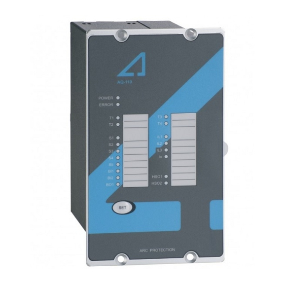
Instruction manual – AQ 110 arc protection unit 7 (80 ENERAL AQ 110 is a sophisticated micro-processor based arc flash protection unit with combined current and arc sensing. Combined current and arc sensing provides an integrated dual trip criteria. It is designed to minimize the damage caused by an arcing fault (arc flash) by tripping the circuit breaker sourcing the fault current. - Page 8 Instruction manual – AQ 110 arc protection unit 8 (80 1 binary output (24Vdc) 1 system failure relay output Figure 2-1 Arc protection unit AQ 110...
-
Page 9: Simplified Block Diagram
Instruction manual – AQ 110 arc protection unit 9 (80 IMPLIFIED BLOCK DIAGRAM Simplified block diagrams in Figure 2-2: AQ110P simplified block diagram and Figure 2-3: AQ 110F simplified block diagram show the main components of the AQ110 unit. Figure 2-2: AQ110P simplified block diagram... - Page 10 Instruction manual – AQ 110 arc protection unit 10 (80 Figure 2-3: AQ 110F simplified block diagram...
-
Page 11: Operation And Configuration
Instruction manual – AQ 110 arc protection unit 11 (80 PERATION AND CONFIGURATION INDICATOR FUNCTIONS AQ 110 contains 20 indication LEDs. A user definable text pocket can be slid in for identifying each LED function (except Power and Error LEDs). LEDs are located at the front plate of the unit for clear viewing without a need for opening doors. -
Page 12: Led Operation Quick Guide
Instruction manual – AQ 110 arc protection unit 12 (80 power supply loss the actual LED status can be visualized from the front of the unit. LED OPERATION QUICK GUIDE The table below describes the function of each indicator LED in front of the AQ 110 unit. - Page 13 Instruction manual – AQ 110 arc protection unit 13 (80 N/A in AQ 110F Normal status Sensor channel Fiber sensor Check why sensor activated or 5 activated discontinuity or check the sensor continuity or system set-up perform system set-up (see Amber N/A in AQ 110F not performed...
-
Page 14: Push-Button Description
Instruction manual – AQ 110 arc protection unit 14 (80 BUTTON DESCRIPTION AQ 110 contains one single push-button (SET) that can be used for all operational functions of the unit. The push-button is utilized for auto-configuration of the system (see chapter 3.3.1) and for resetting the indicators and latched output relays. -
Page 15: Current Threshold Setting
Instruction manual – AQ 110 arc protection unit 15 (80 URRENT THRESHOLD SETTING AQ 110 unit has 4 current measurement inputs utilized for 3 phase and residual current measurement. Both phase current and residual current measurements are utilized as second trip criteria in an arc protection system in order to avoid trip caused by natural light sources. - Page 16 Instruction manual – AQ 110 arc protection unit 16 (80 (CBFP) scheme may be enabled using the dipswitches. See Table 3-2 AQ 110 dipswitch SW 1 setting and Table 3-3: AQ 110 dipswitch SW 2 setting for details of settings. Figure 3-1 AQ 110 dipswitch SW1 and SW2 Dipswitch Function selection...
- Page 17 Instruction manual – AQ 110 arc protection unit 17 (80 Dipswitch Function selection ON (LEFT OFF (RIGHT POSITION) POSITION) Latch or non-latch for T1 and T2 operate as T1 and T2 operate as trip relays T1 and T2 latched. non-latched. T1/T2 Latch/non- latch Latch or non-latch for...
- Page 18 Instruction manual – AQ 110 arc protection unit 18 (80 Figure 3-2: AQ 110P internal logic. Figure 3-3: AQ 110F internal logic...
-
Page 19: Non-Volatile Memory
Instruction manual – AQ 110 arc protection unit 19 (80 VOLATILE MEMORY All critical system data including dipswitch settings and auto-configuration file described in chapter 3.3.1 are stored in EPROM non-volatile memory to ensure correct operation and full self-supervision even if auxiliary power is lost temporarily. -
Page 20: Arc Sensors
Instruction manual – AQ 110 arc protection unit 20 (80 ENSORS AQ 100 series provides choice of different types of arc sensors to be utilized in different units and different switchgear types according to specific application requirements. Available sensor types are arc light point sensors and arc light fiber optic loop sensors. -
Page 21: Aq 01 Installation And Wiring
Instruction manual – AQ 110 arc protection unit 21 (80 Figure 4-1: Arc sensor AQ 01 4.1.1 AQ 01 I NSTALLATION AND WIRING AQ 01 is installed either on the compartment wall or through wall. Example of wall mounting is seen in Figure 4-2. AQ 01 is fixed to the wall using two screws. The same screw pattern is utilized in through wall mounting arrangement as well. - Page 22 Instruction manual – AQ 110 arc protection unit 22 (80 Figure 4-2: AQ 01 mounted to compartment wall. AQ01 comes without connection cable. Connection cable installation at site is simple. Cable connectors are located beneath the covers that can be conveniently detached for fastening the sensor wires.
-
Page 23: Aq 01 Technical Data
AQ 06 is not recommended to be cut and/or spliced on site. If cutting/splicing is necessary due to accidental breakage please contact your nearest Arcteq representative. The fixed light sensitivity of the AQ06 sensor is 8000 LUX. Sensor does not... -
Page 24: Aq 06 Technical Data
Figure 4.3 AQ 06 arc light fiber optic loop sensor Note: On request AQ 06 ends can be covered with black rubber part for any requested portion to avoid light detection outside the protected zone. For more information consult your nearest Arcteq representative. 4.2.1 AQ 06 T ECHNICAL DATA... -
Page 25: Arc Light Fiber Optic Loop Sensor Aq 07
AQ 07 is not recommended to be cut and/or spliced on site. If cutting/splicing is necessary due to accidental breakage please contact your nearest Arcteq representative. The fixed light sensitivity of the AQ07 sensor is 8000 LUX. Sensor does not require user settings. -
Page 26: Aq 07 Technical Data
AQ 08 is not recommended to be cut and/or spliced on site. If cutting/splicing is necessary due to accidental breakage please contact your nearest Arcteq representative. The fixed light sensitivity of the AQ08 sensor is 8000 LUX. Sensor does not... -
Page 27: Aq 08 Technical Data
Figure 4.5 AQ 08 arc light fiber optic loop sensor Note: On request AQ 08 ends can be covered with black rubber part for any requested portion to avoid light detection outside the protected zone. For more information consult your nearest Arcteq representative. 4.4.1 AQ 08 T ECHNICAL DATA... -
Page 28: Sensor Type Dependencies
Instruction manual – AQ 110 arc protection unit 28 (80 ENSOR EPENDENCIES Different sensor types can be utilized in different arc flash protection units of the AQ 100 series. The table below describes the dependencies. Table 4-1: Arc sensor dependencies AQ 01 AQ06 AQ07... - Page 29 Instruction manual – AQ 110 arc protection unit 29 (80 2) Before connecting the cable to connector, make sure that the connecting order is right ( + , signal , shield). The appropriate pins information is shown on the blue bottom part of the sensor.
- Page 30 Instruction manual – AQ 110 arc protection unit 30 (80 4) Check the front panel of the unit, only POWER LED turns on at this moment. (See Figure 4.9) Figure 4.9...
- Page 31 Instruction manual – AQ 110 arc protection unit 31 (80 5) Attach the connector back to the sensor PCB. (See Figure 4.10) Figure 4.10 6) After connecting the sensor to unit, the ERROR LED turns on, and the appropriate sensor channel LED starts to blink (e.g.S1 LED).(See Figure 4.11) Figure 4.11...
- Page 32 Instruction manual – AQ 110 arc protection unit 32 (80 7) Press and hold the SET push button on the front panel for 2 seconds in order to run system auto-configuration setting.(See Figure 4.12) The unit memorizes the sensor amount and Binary input lines connected (if any). Figure 4.12 8) After completing the system auto-configuration setting, close both end side- covers back.
- Page 33 Instruction manual – AQ 110 arc protection unit 33 (80 9) A maximum amount of 3 arc sensors can be daisy-chained to the same sensor input on the AQ101 unit. (See Figure 4.14) Figure 4.14 The Auto Configuration is a part of the Self Supervision Function which is making sure that all connections and sensors at all time are fully functional and ready to operate.
-
Page 34: System Self-Supervision
Instruction manual – AQ 110 arc protection unit 34 (80 YSTEM SELF SUPERVISION AQ 110 includes extensive self-supervision feature. Self-supervision includes both internal functions and external connections. The self-supervision module monitors power supply, HW and SW malfunctions and binary input connection and sensor problems. -
Page 35: Standard Arc Schemes (Aq Sas)
The AQ 100 series is applicable for other type of schemes as well. If your particular application is not included in AQ SAS library consult your nearest Arcteq representative for a solution. -
Page 36: Scheme Aq 0A (One Main)
Instruction manual – AQ 110 arc protection unit 36 (80 6.1 S AQ 0A (O CHEME 6.1.1 S CHEME CHARACTERISTICS Number of incoming feeders Number of tie breakers Selective trip of feeder circuit breaker Master trip function Units applied AQ 110P Figure 6-1: Scheme 0A single-line diagram... -
Page 37: I/Odescription
Instruction manual – AQ 110 arc protection unit 37 (80 6.1.2 I/O DESCRIPTION AQ 110P: Function IL1,IL2,IL3 Monitoring of phase overcurrent threshold level at incoming feeder 1 Monitoring of residual current threshold level at incoming feeder 1 Monitoring of arc light in incoming feeder 1 cable compartment and bus-duct (Zone 1) S2, S5 Monitoring of arc light in incoming feeder 1... -
Page 38: Trip Logic, Connection Diagram And Dipswitch Settings
Instruction manual – AQ 110 arc protection unit 38 (80 6.1.3 T RIP LOGIC CONNECTION DIAGRAM AND DIPSWITCH SETTINGS CB4-x Zone 1 Zone 2 Zone 3 AQ 110 T3,T4 Table 6-1: Scheme 0A trip logic Figure 6-2: Scheme IA1 system connection diagram and dipswitch settings... -
Page 39: Scheme Aq Ia1 (One Main)
Instruction manual – AQ 110 arc protection unit 39 (80 AQ IA1 (O CHEME 6.2.1 S CHEME CHARACTERISTICS Number of incoming feeders Number of tie breakers Selective trip of feeder circuit breaker Master trip function Units applied AQ 110P and AQ 101 Figure 6-3: Scheme IA1 single-line diagram... -
Page 40: I/Odescription
Instruction manual – AQ 110 arc protection unit 40 (80 6.2.2 I/O DESCRIPTION AQ 110P: Function IL1,IL2,IL3 Monitoring of phase overcurrent threshold level at incoming feeder 1 Monitoring of residual current threshold level at incoming feeder 1 Monitoring of arc light in incoming feeder 1 cable compartment and bus-duct (Zone 1) S2, S3 Monitoring of arc light in incoming feeder 1... -
Page 41: Trip Logic, Connection Diagram And Dipswitch Settings
Instruction manual – AQ 110 arc protection unit 41 (80 AQ101 (all units): Function Monitoring of arc light in outgoing feeder cable compartment for selective trip (Zone 3) Monitoring of arc light in outgoing feeder breaker compartment and busbar compartment (Zone 2) (*) Sending light information to AQ 110 unit of incoming feeder 1 Receiving overcurrent information from AQ 110 unit of... - Page 42 Instruction manual – AQ 110 arc protection unit 42 (80 Figure 6-4: Scheme IA1 system connection diagram and dipswitch settings...
-
Page 43: Scheme Aq Ib1 (One Main)
Instruction manual – AQ 110 arc protection unit 43 (80 AQ IB1 (O CHEME 6.3.1 S CHEME CHARACTERISTICS Number of incoming feeders Number of tie breakers Selective tripping of feeder circuit breaker Master trip function AQ 110P and AQ Units applied Figure 6-5: Scheme IB1 single-line diagram... -
Page 44: I/Odescription
Instruction manual – AQ 110 arc protection unit 44 (80 6.3.2 I/O DESCRIPTION AQ110P: Function IL1,IL2,IL3 Monitoring of phase overcurrent threshold level at incoming feeder 1 Monitoring of residual current threshold level at incoming feeder 1 Monitoring of arc light in incoming feeder 1 cable compartment and bus-duct (Zone 1) S2, S3 Monitoring of arc light in incoming feeder 1... -
Page 45: Trip Logic, Connection Diagram And Dipswitch Settings
Instruction manual – AQ 110 arc protection unit 45 (80 AQ101: Function Not in use (*) S2,S3,S4 Monitoring of arc light in outgoing feeder breaker compartments and busbars compartment (Zone 2) Sending light information to AQ 110 unit of incoming feeder 1 Receiving overcurrent information from AQ 110 unit of incoming feeder 1 Receiving master trip information from AQ 110 unit... - Page 46 Instruction manual – AQ 110 arc protection unit 46 (80 Figure 6-6: Scheme IB1 system connection diagram and dipswitch settings...
-
Page 47: Scheme Aq- Iia1 (Main-Tie-Main)
Instruction manual – AQ 110 arc protection unit 47 (80 AQ- IIA1 (M CHEME 6.4.1 S CHEME CHARACTERISTICS Number of incoming feeders Number of tie breakers Selective trip of feeder circuit breaker Master trip function AQ 110P and AQ Units applied Figure 6-7: Scheme IIA1 single-line diagram. -
Page 48: I/Odescription
Instruction manual – AQ 110 arc protection unit 48 (80 6.4.2 I/O DESCRIPTION AQ110P (Busbar A): Function IL1,IL2,IL3 Monitoring of phase overcurrent threshold level at incoming feeder 1 Monitoring of residual current threshold level at incoming feeder 1 Monitoring of arc light in incoming feeder 1 cable compartment and bus-duct (Zone 1A) S2, S3 Monitoring of arc light in incoming feeder 1... - Page 49 Instruction manual – AQ 110 arc protection unit 49 (80 AQ110P (Busbar B): Function IL1,IL2,IL3 Monitoring of phase overcurrent threshold level at incoming feeder 2 Monitoring of residual current threshold level at incoming feeder 2 Monitoring of arc light in incoming feeder 2 cable compartment and bus-duct (Zone 1B) S2, S3 Monitoring of arc light in incoming feeder 2...
- Page 50 Instruction manual – AQ 110 arc protection unit 50 (80 AQ101 (all units at busbar A): Function Monitoring of arc light in outgoing feeder cable compartment for selective trip (Zone 3A) Monitoring of arc light in outgoing feeder breaker compartment and busbar compartment (Zone 2A) (*) Sending light information to AQ 110 unit of incoming feeder 1 Receiving overcurrent information from AQ 110 unit of...
- Page 51 Instruction manual – AQ 110 arc protection unit 51 (80 AQ101 (all units at busbar B): Function Monitoring of arc light in outgoing feeder cable compartment for selective tripping (Zone 3B) Monitoring of arc light in outgoing feeder breaker compartment and busbar compartment (Zone 2B)(*) Sending light information to AQ 110 unit of incoming feeder 2 Receiving overcurrent information from AQ 110 unit of...
-
Page 52: Trip Logic, Connection Diagram And Dipswitch Settings
Instruction manual – AQ 110 arc protection unit 52 (80 6.4.3 T RIP LOGIC CONNECTION DIAGRAM AND DIPSWITCH SETTINGS CB1A CB2A CB4A-x CB3AB CB1B CB2B CB4B-x Zone 1A Zone 2A x (MT) Zone 3A Zone 1B Zone 2B x (MT) Zone 3B CBFP of CB1A CBFP of CB4A-x... - Page 53 Instruction manual – AQ 110 arc protection unit 53 (80 Figure 6-8: Scheme IIA1 system connection diagram and dipswitch settings.
-
Page 54: Scheme Aq-Iib1 (Main-Tie-Main)
Instruction manual – AQ 110 arc protection unit 54 (80 AQ-IIB1 (M CHEME 6.5.1 S CHEME CHARACTERISTICS Number of incoming feeders Number of tie breakers Selective trip of feeder circuit breaker Master trip function Units applied AQ 110P and AQ Figure 6-9: Scheme IIB1 single line diagram. -
Page 55: I/Odescription
Instruction manual – AQ 110 arc protection unit 55 (80 6.5.2 I/O DESCRIPTION AQ110P (Busbar A): Function IL1,IL2,IL3 Monitoring of phase overcurrent threshold level at incoming feeder 1 Monitoring of residual current threshold level at incoming feeder 1 Monitoring of arc light in incoming feeder 1 cable compartment and bus-duct (Zone 1A) S2, S3 Monitoring of arc light in incoming feeder 1... - Page 56 Instruction manual – AQ 110 arc protection unit 56 (80 AQ110P (Busbar B): Function IL1,IL2,IL3 Monitoring of phase overcurrent threshold level at incoming feeder 2 Monitoring of residual current threshold level at incoming feeder 2 Monitoring of arc light in incoming feeder 2 cable compartment and bus-duct (Zone 1B) S2, S3 Monitoring of arc light in incoming feeder 2...
- Page 57 Instruction manual – AQ 110 arc protection unit 57 (80 AQ101 (Busbar A): Function Not in use (*) S2,S3,S4 Monitoring of arc light in outgoing feeder breaker compartments and busbar compartments (Zone Sending light information to AQ 110 unit of incoming feeder 1 Receiving overcurrent information from AQ 110 unit of incoming feeder 1...
-
Page 58: Trip Logic, Connection Diagram And Dipswitch Settings
Instruction manual – AQ 110 arc protection unit 58 (80 AQ101 (Busbar B): Function Not in use (*) S2,S3,S4 Monitoring of arc light in outgoing feeder breaker compartments and busbar compartments (Zone Sending light information to AQ 110 unit of incoming feeder 2 Receiving overcurrent information from AQ 110 unit of incoming feeder 2... - Page 59 Instruction manual – AQ 110 arc protection unit 59 (80 Figure 6-10: Scheme IIB1 system connection diagram and dipswitch settings.
-
Page 60: Connections
Instruction manual – AQ 110 arc protection unit 60 (80 ONNECTIONS Figure 7-1: AQ 110P terminals at rear plate... - Page 61 Instruction manual – AQ 110 arc protection unit 61 (80 Figure 7-2: AQ 110F terminals at rear plate...
-
Page 62: Outputs
Instruction manual – AQ 110 arc protection unit 62 (80 UTPUTS 7.1.1 T RIP RELAYS The AQ 110 unit has integrated trip relays T1 and T2 for tripping of the circuit- breakers. T1 and T2 relays are normally open type (NO). 7.1.2 T RIP RELAYS T3 relay output may act either as an electronic lock-out relay or as a trip relay. -
Page 63: Binary Output Bo1
Instruction manual – AQ 110 arc protection unit 63 (80 7.1.4 B INARY OUTPUT One binary output is available (+24V dc). Binary output function can be configured using dipswitches (see chapter 3.6 Dipswitch settings). Note: the binary output is polarity sensitive (see chapter 8 Wiring diagram). 7.1.5 S YSTEM FAILURE RELAY System failure relay SF is a changeover type (NO/NC) and is energized in... -
Page 64: Binary Inputs Bi1 And Bi2
Instruction manual – AQ 110 arc protection unit 64 (80 configured to control the arc quenching system (eliminator. In this case Tx shall be utilized to control the arc quenching system. The unit is sending a continuous light pulse to arc quenching system for self-supervision purposes. AQ 110F version has 3 arc fiber loop sensor channels (S1, S2, S3) with transceiver and receiver (Tx, Rx) in each channel. -
Page 65: Wiring Diagrams
Instruction manual – AQ 110 arc protection unit 65 (80 IRING DIAGRAMS Figure 8-1: AQ 110P Wiring diagram... - Page 66 Instruction manual – AQ 110 arc protection unit 66 (80 Figure 8-2: AQ 110F Wiring diagram...
-
Page 67: Dimensions And Installation
Instruction manual – AQ 110 arc protection unit 67 (80 IMENSIONS AND INSTALLATION AQ 110 is either door mounted or panel mounted in standard 19 inch rack (height of 4U and 1/4 of a unit wide). Figure 9-1: AQ 110 dimensions in millimeters (side view) - Page 68 Instruction manual – AQ 110 arc protection unit 68 (80 Figure 9-2: AQ 110 dimensions in millimeters (3D view)
- Page 69 Instruction manual – AQ 110 arc protection unit 69 (80 Figure 9-3: AQ 110 cut out for panel mounting (millimeters)
-
Page 70: Testing
Instruction manual – AQ 110 arc protection unit 70 (80 10 T ESTING It is recommended that the AQ 110 unit is tested prior to substation energizing. Testing is carried out by simulating arc light to each sensor and verifying the tripping and LED indication. -
Page 71: Carrying Out Testing In Light And Current Mode
Instruction manual – AQ 110 arc protection unit 71 (80 10.2 C ARRYING OUT TESTING IN LIGHT AND CURRENT MODE Check that the dipswitch setting positions are in accordance with your application Activate the camera flash within 20cm (12 inches) of the AQ01 sensor unit and activate the binary input BI1 used for overcurrent condition simultaneously. -
Page 72: Testing The Cbfp Function
The AQ 110 operation time test is not required at commissioning as it is performed by the manufacturer as a type test and routine production test. Refer to routine test reports sent with AQ 110 unit and consult your nearest Arcteq representative for type test reports. -
Page 73: Test Plan Example
Instruction manual – AQ 110 arc protection unit 73 (80 10.5 T EST PLAN EXAMPLE Date: Substation Switchgear: AQ 110 serial number: Preconditions Light only Light + Remark current Sensor channel 1 setting Sensor channel 2,3,4 setting Circuit breaker failure protection in use (Yes / No): Object... - Page 74 Instruction manual – AQ 110 arc protection unit 74 (80 Tested by : Approved by:...
-
Page 75: Troubleshooting Guide
Instruction manual – AQ 110 arc protection unit 75 (80 11 T ROUBLESHOOTING GUIDE Problem Check Cross reference Sensor does not activate when Sensor cable wiring Chapter 4.6 of this manual testing Camera (or other test equipment) Chapter 10 of this manual flash intensity Trip relay(s) does not operate Dipswitch settings and current... -
Page 76: Technical Data
Instruction manual – AQ 110 arc protection unit 76 (80 12 T ECHNICAL DATA 12.1 P ROTECTION STAGES Trip time using HSO 2ms* Trip time using mechanical trip relays 7ms* Reset time (light stage) Reset time (overcurrent stages) 50ms Protection operational after power up 50ms *total trip time using arc light (L>) or phase/residual overcurrent (I>) and arc light (L>) 12.2 A... -
Page 77: Binary Output Bo1
Instruction manual – AQ 110 arc protection unit 77 (80 12.6 B INARY UTPUT Rated voltage +24V dc (internally wetted) Rated current 20mA (max) Number of outputs 12.7 B BI1, BI2 INARY NPUTS Rated voltage 24 or 110 or 220Vdc Rated current 3 mA Number of inputs... -
Page 78: Casing And Package
Instruction manual – AQ 110 arc protection unit 78 (80 12.11 C ASING AND PACKAGE Protection degree (front) IP 54 Dimensions (W x H x D mm) w x h x d mm Weight 1.2kg 1.5kg (with package) 12.12 E NVIRONMENTAL CONDITIONS Specified ambient service temp. -
Page 79: Ordering Codes
Instruction manual – AQ 110 arc protection unit 79 (80 13 O RDERING CODES 13.1 AQ 110 P OINT SENSOR UNIT AQ - 1 1 0 x X X X X Sensor card version P Point sensor unit F Fiber sensor unit Auxiliary power supply A 80…265 Vac/dc B 18…72 Vdc... -
Page 80: Reference Information
Instruction manual – AQ 110 arc protection unit 80 (80 14 R EFERENCE INFORMATION Manufacturer information: Arcteq Relays Ltd. Finland Visiting and postal address: Wolffintie 36 F 11 65200 Vaasa, Finland Contacts: Phone: +358 10 3221 370 Fax: +358 10 3221 389 url: www.arcteq.fi...
Need help?
Do you have a question about the AQ 110 Series and is the answer not in the manual?
Questions and answers