Table of Contents
Advertisement
Quick Links
Advertisement
Table of Contents

Subscribe to Our Youtube Channel
Related Manuals for Arcteq AQ-103LV


Summary of Contents for Arcteq AQ-103LV
- Page 1 AQ-103LV Arc flash protection device Instruction manual...
-
Page 3: Table Of Contents
13.1 Operating times ......................... 38 13.2 Auxiliary voltage......................... 38 13.3 Binary inputs........................38 13.4 Trip relays .......................... 38 13.5 High-speed output(s) ......................38 13.6 Binary output(s) ......................... 39 13.7 System failure relay......................39 13.8 Point sensors ........................39 © Arcteq Relays Ltd IM00045... - Page 4 13.14 Casing..........................42 14 Or 14 Ordering inf dering informa ormation tion ..............................................43 15 Contact and r 15 Contact and re e f f er erence inf ence informa ormation tion......................................45 © Arcteq Relays Ltd IM00045...
- Page 5 Nothing contained in this document shall increase the liability or extend the warranty obligations of the manufacturer Arcteq Relays Ltd. The manufacturer expressly disclaims any and all liability for any damages and/or losses caused due to a failure to comply with the instructions contained herein or caused by persons who do not fulfil the aforementioned requirements.
- Page 6 A A Q Q -103L -103LV V Instruction manual Version: 1.02 Copyright Copyright © Arcteq Relays Ltd. 2023. All rights reserved. © Arcteq Relays Ltd IM00045...
-
Page 7: Document Informa Ormation Tion
1.02 Date January 2023 - Updated the Arcteq logo on the cover. - Updated the distance between the flash and the unit in the "Testing the unit operation time" chapter. - Unified terminology used througout the manual (e.g. unit and device means the same thing. -
Page 8: Abbr Bbre E Via Viations Tions
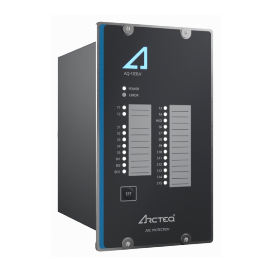
NC – normally closed NO – normally open PCB – printed circuit board RF – radio frequency Rx – receiver SAS – standard arc scheme SF – system failure Tx – transceiver μP - microprocessor © Arcteq Relays Ltd IM00045... - Page 9 Figure. 3 - 1. Arc protection device AQ-103LV. The AQ-103LV is designed according to the latest protection relay standards and it is therefore suitable for installations in rough environments. These include utilities and power plants (both traditional and renewable), various heavy industry applications (oil, gas, mining, steel, etc.) as well as commercial and...
- Page 10 4 Device features AQ-103LV is an arc flash protection device which can be applied to a variety of applications. It can be used on its own as a stand-alone device, or it can be a part of a more complex arc protection system by using binary inputs and outputs to connect multiple AQ 100 series devices together.
-
Page 11: Connections
Figure. 5 - 2. Rear terminals of the AQ-103(LV) with optional Modbus add-on. 5.1 Simplified block diagram The figure below presents the main components of the AQ-103LV device. © Arcteq Relays Ltd IM00045... - Page 12 A A Q Q -103L -103LV V Instruction manual Version: 1.02 Figure. 5.1 - 3. Simplified block diagram of the AQ-103 with optional Modbus add-on. © Arcteq Relays Ltd IM00045...
-
Page 13: Inputs
For more information on sensors, please refer to the Arc sensors chapter as well as to the AQ-0x instruction booklet which can be found on Arcteq's website (https://www.arcteq.fi/downloads/). For more information on AQ-1000 arc quenching device (AQD) please refer to the AQ-1000 Instruction manual. -
Page 14: Outputs
The device contains one (1) high-speed semiconductor output, abbreviated HSO. The output’s direction of rotation is as follows: the signal goes in the even pin and out from the odd pin (see the image below, as detailed in the device’s side sticker). © Arcteq Relays Ltd IM00045... -
Page 15: Trip Relays
Trip relays can be set as latching relays by setting DIP switch SW1:6 ("Latching / Non-latching") to "Latching" position. Latched relays can be reset by pressing the "SET" button. 5.3.4 System failure relay Figure. 5.3.4 - 10. System failure relay connection (de-energized position) © Arcteq Relays Ltd IM00045... -
Page 16: Auxiliary Voltage
Figure. 5.4 - 11. Auxiliary power supply connection The auxiliary power supply voltage is 92….265 V AC/DC. Alternatively, the optional auxiliary power supply can be of 18…72 V DC. This choice must be specified when ordering. © Arcteq Relays Ltd IM00045... -
Page 17: Arc Sensors C Sensors
Installing a connection cable is simple as each end of the sensor has a detachable cover over the cable connectors. Please remember to reattach the cover once the wires have been installed. NOTE! The AQ-01 point sensor does no not t come with a connection cable! © Arcteq Relays Ltd IM00045... -
Page 18: Arc Light And Pressure Point Sensor Aq-02
AQ-07 sensors can be ordered in pre-manufactured lengths of 3…50 meters (3 m, 5 m, 10 m, 15 m, 20 m, 25 m, 30 m, 35 m, 40 m, 45 m, 50 m). © Arcteq Relays Ltd IM00045... -
Page 19: Arc Light Fiber Optic Loop Sensor Aq-08
If necessary, the ends of an AQ-07 cable can be ordered with heat shrinking tubing to avoid light detection outside the protected zone. The covered area can be one (1) or two (2) meters by default; if other lengths are required, please consult the Arcteq sales team. You can find the Contact and reference information page at the end of this manual. -
Page 20: Fiber Loop Sensors
2. Install protective covers in the holes to ensure the sensor cable remains unharmed by rough edges. 3. Run the sensor cable through the holes and along the protected area. Fasten it to the compartment walls with cable clips or some other appropriate anchoring method. © Arcteq Relays Ltd IM00045... - Page 21 Instruction manual Version: 1.02 4. Turn the black and blue receiver (“Rx”) and transceiver (“Tx”) screws counter-clockwise and plug in the sensor cable terminals. Then turn the screws clockwise to secure the terminals in their place. © Arcteq Relays Ltd IM00045...
-
Page 22: Operation And Config Tion And Configura Uration Tion
Selects whether the The outputs (T1–T4, HSO, Blocking outputs (T1–T4, HSO, BO1 BO1 and AQD) are Normal operation. function and AQD) are blocked. blocked. reserved (Reserved for future use.) — — © Arcteq Relays Ltd IM00045... -
Page 23: Scheme Selection
(can be found at arcteq.fi/downloads/). 7.1.2 Available logic schemes Below you can see descriptions of the most commonly used logic schemes available to the AQ-103LV device. The basic logic is the same in all the logic schemes: © Arcteq Relays Ltd... - Page 24 Figure. 7.1.2 - 17. The trip logic matrix of SS:0. 1) Activates only if DIP-switch has been set to light only mode or if overcurrent signal (BI1) is ON. 2) Activates only if overcurrent signal (BI1) is ON. © Arcteq Relays Ltd IM00045...
- Page 25 The sensor channels S1 and S2 do not activate the AQD control. All sensors trip all trip relays (T1–T4) as well as the high-speed output (HSO) and the binary output (BO1). When the blocking function is selected, it prevents all tripping activations apart from LED activations. © Arcteq Relays Ltd IM00045...
- Page 26 1) Activates only if DIP-switch has been set to light only mode or if overcurrent signal (BI1) is ON. 2) Activates only if overcurrent signal (BI1) is ON. Figure. 7.1.2 - 20. Simplified logic diagram of SS:1. © Arcteq Relays Ltd IM00045...
- Page 27 Figure. 7.1.2 - 21. The trip logic matrix of SS:2. 1) Activates only if DIP-switch has been set to light only mode or if overcurrent signal (BI1) is ON. 2) Activates only if overcurrent signal (BI1) is ON. © Arcteq Relays Ltd IM00045...
-
Page 28: Push Button (Set)
1. Setting up the system (also known as auto-configuration) 2. Resetting the indicator LEDs 3. Resetting latched outputs 4. Checking the input connections Figure. 7.2 - 23. The "SET" push button on the device's front panel. © Arcteq Relays Ltd IM00045... -
Page 29: System Setup (Auto-Configuration)
7.3 LED indicator functions The AQ-103LV device has twenty-five (25) indication LEDs on the device's front panel.. Apart from the “Power” and “Error” LEDs, the user can write their own identifications for each of the remaining LEDs on the text insert sheet located in the transparent pockets next to the LEDs. -
Page 30: Led Operations Guide
AQ-103 and AQ-103LV can be ordered with Modbus RTU serial communication to report various signals to external devices. It is mainly designed for connecting to AQ-S254 but any Modbus master can be used. Up to 16 AQ-103 or AQ-103LV devices can be connected to one system. Modbus polling rate The recommended maximum polling rate for the Modbus protocol is twice per second (2/s). -
Page 31: Non-Volatile Memory
This feature is especially important if tripping causes the device to lose its auxiliary power. The non-volatile memory does not require a power supply to maintain the information and it retains the settings and the indications permanently without power. © Arcteq Relays Ltd IM00045... -
Page 32: Sy Y St Stem Self-Super 8 S Em Self-Supervision Vision
The device goes into Error mode, if a DIP switch setting is changed after the system setup procedure has been performed. However, the configured (stored) settings are still valid and the device is still operational. © Arcteq Relays Ltd IM00045... - Page 33 A A Q Q -103L -103LV V Instruction manual Version: 1.02 9 Wiring example Figure. 9 - 24. Example wiring diagram for AQ-103LV. © Arcteq Relays Ltd IM00045...
-
Page 34: Dimensions And Installa Imensions And Installation Tion
Instruction manual Version: 1.02 10 Dimensions and installation AQ-103LV can be either door-mounted or panel-mounted in a standard 19 inch rack. The device’s dimensions (without PCBs) are as follows: • Height: 157 mm (6.18 in) • Width: 102 mm (4.02 in) •... - Page 35 A A Q Q -103L -103LV V Instruction manual Version: 1.02 Figure. 10 - 26. Installing a device into a cut-out. © Arcteq Relays Ltd IM00045...
-
Page 36: Testing Esting
9. Activate the camera flash within 30 cm (12 inches) of the sensor but do not activate the binary input used for the overcurrent condition (I>). 10. Verify that no trip has occured and only the indicator LED of the sensor activation is lit. © Arcteq Relays Ltd IM00045... -
Page 37: Testing The Operation Time
If you want to have more information of these tests, please refer to the routine test reports sent with the AQ-103(LV) device and/or consult your nearest Arcteq representative for the type test reports. - Page 38 A A Q Q -103L -103LV V Instruction manual Version: 1.02 © Arcteq Relays Ltd IM00045...
-
Page 39: Tr R Oubleshoo 12 T Oubleshooting Ting
(see the DIP switch settings chapter for more information). The system gives an alarm that Check that each sensor channel only has one sensor connected to it. cannot be cleared or installed. © Arcteq Relays Ltd IM00045... -
Page 40: Technic Echnical Da Al Data Ta
16 A - make-and-carry for 0.5 s 30 A Breaking capacity DC* 40 W (0.36 A at 110 V DC) Contact material AgNi 90/10 *) When the time constant L/R = 40 ms. 13.5 High-speed output(s) © Arcteq Relays Ltd IM00045... -
Page 41: Binary Output(S)
Light intensity threshold 25,000 lux 50,000 lux Detection radius 180º Mechanical protection IP 20 Sensor cable specification Shielded twisted pair 0.75 mm (AWG: 18) Maximum sensor cable length (per channel) 200 m Operating temperature –20…+85 ºC © Arcteq Relays Ltd IM00045... -
Page 42: Fiber Optic Loop Sensors
Bending radius 1 cm Operating temperature –40…+85 ºC AQ-08 fiber optic loop sensor Table. 13.9 - 20. Technical data for the AQ-08 fiber optic loop sensor. Material Covered glass fiber Light intensity threshold 8,000 lux © Arcteq Relays Ltd IM00045... -
Page 43: Disturbance Tests
Table. 13.13 - 24. Technical data for the environmental conditions. Specified ambient service temperature –35…+70 ºC Transportation and storage temperature –40…+70 ºC Relative humidity Up to 97 % Altitude Up to 2,000 m above sea level © Arcteq Relays Ltd IM00045... -
Page 44: Casing
Table. 13.14 - 25. Technical data for the device casing. Protection: - front IP 52 - back IP 20 Device dimensions (W × H × D) 102 × 177 × 161 mm Weight 1.2 kg © Arcteq Relays Ltd IM00045... -
Page 45: Ordering Inf Dering Informa Ormation Tion
A A Q Q -103L -103LV V Instruction manual Version: 1.02 14 Ordering information AQ-103LV arc flash protection device AQ-0x point sensors © Arcteq Relays Ltd IM00045... - Page 46 Accessories Order code Description Note Manufacturer AQX006 Wall mounting bracket For AQ-103 and AQ-110x variants (MV and LV). Arcteq Ltd. AQX016 Wall mounting bracket For AQ-101, AQ-101S and AQ-102 devices (MV and LV). Arcteq Ltd. © Arcteq Relays Ltd IM00045...
-
Page 47: Contact And R Ence Informa Ormation Tion
Arcteq Relays Ltd. Visiting and postal address Kvartsikatu 2 A 1 65300 Vaasa, Finland Contacts Phone: +358 10 3221 370 Website: arcteq.fi Technical support: support.arcteq.fi +358 10 3221 388 (EET 9:00 – 17.00) E-mail (sales): sales@arcteq.fi © Arcteq Relays Ltd IM00045...
Need help?
Do you have a question about the AQ-103LV and is the answer not in the manual?
Questions and answers