Arcteq AQ-101 Instruction Manual
Arc flash protection unit
Hide thumbs
Also See for AQ-101:
- Instruction manual (52 pages) ,
- Instruction manual (19 pages) ,
- Instruction manual (75 pages)
Table of Contents
Advertisement
Quick Links
Advertisement
Table of Contents

Related Manuals for Arcteq AQ-101


Summary of Contents for Arcteq AQ-101
- Page 1 AQ-101 (AQ-101D) Arc flash protection unit Instruction manual...
-
Page 3: Table Of Contents
.......................... 37 11.1 Mounting and installation ....................37 11.2 Operating times ......................... 37 11.3 Auxiliary voltage......................... 38 11.4 Binary inputs........................38 11.5 Trip relays .......................... 38 11.6 Binary output(s) ......................... 38 11.7 System failure relay......................39 © Arcteq Relays Ltd IM00006... - Page 4 11.13 Casing..........................41 12 Or 12 Ordering inf dering informa ormation tion ..............................................42 13 Contact and r 13 Contact and re e f f er erence inf ence informa ormation tion......................................44 © Arcteq Relays Ltd IM00006...
- Page 5 Nothing contained in this document shall increase the liability or extend the warranty obligations of the manufacturer Arcteq Relays Ltd. The manufacturer expressly disclaims any and all liability for any damages and/or losses caused due to a failure to comply with the instructions contained herein or caused by persons who do not fulfil the aforementioned requirements.
- Page 6 A A Q Q -101 (A -101 (AQ Q -101D -101D) ) Instruction manual Version: 2.01 Copyright Copyright © Arcteq Relays Ltd. 2021. All rights reserved. © Arcteq Relays Ltd IM00006...
-
Page 7: Document Inf
1.03 1.03 Date November 2012 Changes - AQ-101 simplified block diagram revised: the name of the BI2 on X1 connector is corrected. Table. 1 - 2. History of Revision 2. R R e e vision vision 2.00 2.00 Date October 2020 - Content completely rewritten to improve grammar and readability. - Page 8 - The IP classification of point sensors updated. - The AWG value updated. - "Disturbance tests" table reformatted. - Order code images updated. - The number for Arcteq's technical support added to the reference information. © Arcteq Relays Ltd IM00006...
-
Page 9: Abbr Bbre E Via Viations Tions
NO – normally open PCB – printed circuit board QD – quenching device RF – radio frequency Rx – receiver SAS – standard arc scheme SF – system failure Tx – transceiver μP - microprocessor © Arcteq Relays Ltd IM00006... -
Page 10: General
3.1 Unit features AQ-101 is a multipurpose arc flash protection unit and can be applied to a variety of applications. It can be used on its own as a stand-alone unit, or it can be a part of a more complex arc protection system through a binary bus. -
Page 11: Dimensions And Installation
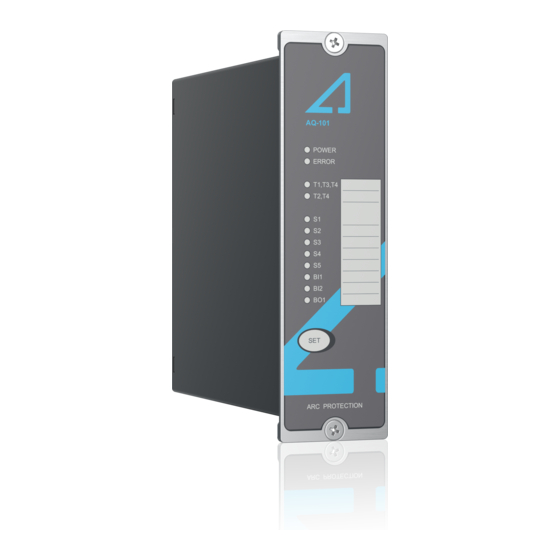
Figure. 3.1 - 1. Arc protection units AQ-101 (left) and AQ-101D (right). 3.2 Dimensions and installation AQ-101 can be either door-mounted or panel-mounted in a standard 19 inch rack. The unit's dimensions (without cards) are as follows: • Height: 157 mm (6.18 in) •... - Page 12 A A Q Q -101 (A -101 (AQ Q -101D -101D) ) Instruction manual Version: 2.01 Figure. 3.2 - 2. Dimensions of the device and its cut-out panel. © Arcteq Relays Ltd IM00006...
-
Page 13: Simplified Block Diagram
Figure. 3.2 - 3. Dimensions of the DIN rail variant of the device. The following image illustrates how a unit is installed into a cut-out. Please note that as AQ-101 is narrower than the unit in the image, they are connected to the cut-out panel by a single screw on both the top and the bottom of the front panel instead of the two depicted below. - Page 14 -101 (AQ Q -101D -101D) ) Instruction manual Version: 2.01 The figure below presents the main components that can be found in both the AQ-101 unit and the AQ-101D variant. Figure. 3.3 - 5. Simplified block diagram of AQ-101 and AQ-101D. NOTE! Please note that the latching (or non-latching) of trip relays T1 and T2 is determined with the DIP switch (SW1:6).
-
Page 15: Wiring
A A Q Q -101 (A -101 (AQ Q -101D -101D) ) Instruction manual Version: 2.01 3.4 Wiring Figure. 3.4 - 6. Wiring diagram for AQ-101 and AQ-101D. AQ-101 Station battery Uaux L> / L> + I> S1: L> / L> + I>... -
Page 16: Operation And Config Tion And Configura Uration Tion
4 Operation and configuration 4.1 LED indicator functions Both the AQ-101 and its AQ-101D variant have twelve (12) indication LEDs. Apart from the "Power" and "Error" LEDs, the user can write their own identifications for each of the remaining LEDs on the text insert located in the transparent pocket next to the LEDs. -
Page 17: Push Button (Set)
Then, all LEDs are turned off. Additionally, the DIP switch setting are stored in the non-volatile memory during this sequence. All sensor inputs remain operational even when they have not been auto-configured. System setup is only used for self-supervision purposes. © Arcteq Relays Ltd IM00006... -
Page 18: Reset
NOTE! Please note that while the pin numbers and their functions are the same for both AQ-101 and AQ-101D, in the DIN rail variant of the unit the pins are "upside down" (that is, Pin 1 is at the top of the DIP switch when normally Pin 8 is at the top)! ©... - Page 19 "Application selection" and "Application (scheme select) examples" chapters. examples" chapters. Please refer to the "Scheme Please refer to the "Scheme Scheme selection. selection" and "Application selection" and "Application (scheme select) examples" chapters. examples" chapters. © Arcteq Relays Ltd IM00006...
-
Page 20: Scheme Selection
DIP switches numbered 1…4 ("Scheme selection"). For detailed instructions on each of the available schemes please refer to the AQ-SAS™ booklet (can be found at arcteq.fi/downloads/). Please note that there are four booklets: two are for schemes based on IEC standards (MV and LV versions) and the other two for schemes based on ANSI standards (MV and LV versions). - Page 21 The trip contact T1 is responsible for tripping the circuit breaker of the outgoing feeder. You can find a more detailed description of this scheme in the AQ-SAS booklet. Figure. 4.4.2 - 12. The logic diagram of SS:1. © Arcteq Relays Ltd IM00006...
-
Page 22: Non-Volatile Memory
This feature is especially important if tripping causes the unit to lose its auxiliary power. The non-volatile memory does not require a power supply to maintain the information and it retains the settings and the indications permanently without power. © Arcteq Relays Ltd IM00006... -
Page 23: Arc Sensors C Sensors
Please remember to reattach the cover once the wires have been installed. NOTE! The AQ-01 point sensor does no not t come with a connection cable! © Arcteq Relays Ltd IM00006... -
Page 24: Arc Light And Pressure Point Sensor Aq-02
20 m, 25 m, 30 m, 35 m, 40 m, 45 m, 50 m). The fixed light intensity threshold of an AQ-07 sensor is 8,000 lux. The sensor does not require further settings by the user. The sensor's detection radius is 360 degrees. © Arcteq Relays Ltd IM00006... -
Page 25: Arc Light Fiber Optic Loop Sensor Aq-08
The covered area can be one (1) or two (2) meters by default; if other lengths are required, please consult the Arcteq sales team. You can find the "Contact and reference information" page at the end of this manual. - Page 26 (1) or two (2) meters of the fiber on each end. Please refer to the "Arc light fiber optic loop sensor AQ-07" chapter for more information. © Arcteq Relays Ltd IM00006...
-
Page 27: Sy Y St Stem Self-Super 6 S Em Self-Supervision Vision
Version: 2.01 6 System self-supervision All AQ-101 and AQ-102 variants (that is, both LV and MV) have an extensive self-supervision feature, including both internal functions and external connections. The self-supervision module monitors the power supply, hardware and software malfunctions, as well as problems with the binary input connection(s) and sensor(s). -
Page 28: Applica A Tion Examples
7 ms, as that is dependent on the device feeding the I> signal to the AQ-101 (or AQ-101D) unit. Please note that the S1 sensor channel can be set to operate solely on the light condition, even if other channels are set to operate on both conditions. -
Page 29: Wind Power Application (Light Only)
Version: 2.01 7.2 Wind power application (light only) AQ-101 and AQ-101D can be applied by using arc light as the only tripping criterion. This example application describes a typical wind power scheme, where a permanent magnet synchronous generator is applied with a converter cabinet and an MV/LV transformer. -
Page 30: Circuit Breaker Failure Protection
Version: 2.01 7.3 Circuit breaker failure protection All AQ-101 variants include a selective circuit breaker failure (CBFP) function, which can be enabled through the DIP switch settings (please refer to the "DIP switch settings" chapter for more information). When enabled, the CBFP function activates when the tripped breaker fails to operate, or if the unit detects the presence of light after a set operating time. -
Page 31: Connections
-101D) ) Instruction manual Version: 2.01 8 Connections The figures below depict the connections of AQ-101 and AQ-101D. Please note that the SF relay is in the de-energized position. Figure. 8 - 19. Rear terminals of AQ-101. © Arcteq Relays Ltd... -
Page 32: Outputs
T4 is a common trip relay that operates whenever T1 or T2 operates. It can be used either for tripping one additional disconnecting device, or as a trip alarm in a (local or remote) monitoring and alarming system. © Arcteq Relays Ltd IM00006... -
Page 33: Binary Outputs
8.2 Inputs 8.2.1 Arc sensor channels Both AQ-101 and AQ-101D have four (4) arc point sensor channels: S1, S2, S3 and S4. You can connect a maximum of three (3) arc point sensors to each channel. S5 is the optional fiber optic loop sensor channel with a transceiver (Tx) terminal and a receiver (Rx) terminal. -
Page 34: Auxiliary Voltage
Instruction manual Version: 2.01 8.3 Auxiliary voltage The auxiliary power supply voltage is 92….265 V AC/DC. Alternatively, the optional auxiliary power supply can be of 18…72 V DC. This choice must be specified when ordering. © Arcteq Relays Ltd IM00006... -
Page 35: Testing Esting
11. Verify that no trip has occured and only the indicator LED of the sensor activation is lit. 12. If you are using the BO1 signal and have configured it to send light information, verify that it is activated. © Arcteq Relays Ltd IM00006... -
Page 36: Testing The Cbfp Function
2. Connect one of the test set's outputs to a strong camera flash to initialize the flash and to configure the set's timer to start simultaneously with the flash. 3. Connect one of the AQ-101 unit's trip outputs (T1, T2, T3, T4) to a test set input and configure the input to stop the timer. -
Page 37: Test Plan Example
A A Q Q -101 (A -101 (AQ Q -101D -101D) ) Instruction manual Version: 2.01 9.5 Test plan example © Arcteq Relays Ltd IM00006... -
Page 38: Tr R Oubleshoo 10 T Oubleshooting Ting
A A Q Q -101 (A -101 (AQ Q -101D -101D) ) Instruction manual Version: 2.01 10 Troubleshooting Table. 10 - 6. Troubleshooting guide for AQ-101 variants. P P r r oblem oblem P P ossible sol ossible solution( ution(s) s) Check the sensor's cable wiring (see the "Arc sensors"... -
Page 39: Technic Echnical Da Al Data Ta
-101 (AQ Q -101D -101D) ) Instruction manual Version: 2.01 11 Technical data 11.1 Mounting and installation Table. 11.1 - 7. Technical data for relay mounting and installation (AQ-101 & AQ-101LV). Panel: - material metal - thickness (min...max) 1.0...5.0 mm (0.04...0.20 in) -
Page 40: Auxiliary Voltage
*) When the time constant L/R = 40 ms. 11.6 Binary output(s) Table. 11.6 - 13. Technical data for the relay binary output (BO1). Number of outputs Rated voltage +24 V DC Rated current (max.) 20 mA © Arcteq Relays Ltd IM00006... -
Page 41: System Failure Relay
Pressure measuring accuracy ±1.8 % (of full scale) Detection radius 180º Mechanical protection IP 20 Sensor cable specification Shielded twisted pair 0.75 mm (AWG: 18) Maximum sensor cable length (per channel) 200 m Operating temperature –20…+85 ºC © Arcteq Relays Ltd IM00006... -
Page 42: Disturbance Tests
–40…+125 ºC 11.9 Disturbance tests Table. 11.9 - 20. Technical data for the disturbance tests. Electromagnetic compatibility test CE-approved and tested according to EN 50081-2 and EN 50082-2 Conducted emission 0.15…30.00 Hz (EN 55011, class A) © Arcteq Relays Ltd IM00006... -
Page 43: Voltage Tests
Protection: - front IP 50 - back IP 20 50 × 157 × 160 mm Device dimensions (W × H × D) 145 × 109 × 34 mm (the DIN rail variant) Weight 0.7 kg © Arcteq Relays Ltd IM00006... -
Page 44: Ordering Inf Dering Informa Ormation Tion
A A Q Q -101 (A -101 (AQ Q -101D -101D) ) Instruction manual Version: 2.01 12 Ordering information AQ-101 point sensor unit (panel mounted) AQ-101D point sensor unit (DIN rail mounted) © Arcteq Relays Ltd IM00006... - Page 45 Accessories Order code Description Note Manufacturer AQX006 Wall mounting bracket For AQ-103 and AQ-110x variants (MV and LV). Arcteq Ltd. AQX016 Wall mounting bracket For AQ-101, AQ-101S and AQ-102 units (MV and LV). Arcteq Ltd. © Arcteq Relays Ltd IM00006...
-
Page 46: Contact And R Ence Informa Ormation Tion
Arcteq Relays Ltd. Visiting and postal address Kvartsikatu 2 A 1 65300 Vaasa, Finland Contacts Phone: +358 10 3221 370 Website: arcteq.fi https://arcteq.fi/support-landing/ Technical support: +358 10 3221 388 (EET 8:00 – 16.00) sales@arcteq.fi E-mail (sales): © Arcteq Relays Ltd IM00006...
Need help?
Do you have a question about the AQ-101 and is the answer not in the manual?
Questions and answers