Table of Contents
Advertisement
Quick Links
Advertisement
Table of Contents

Subscribe to Our Youtube Channel
Related Manuals for Arcteq AQ-T216


Summary of Contents for Arcteq AQ-T216
- Page 1 AQ-T216 Transformer protection device Instruction manual...
-
Page 2: Table Of Contents
3.9 Configuring user levels and their passwords................. 49 4 Functions unctions ...................................................... 52 4.1 Functions included in AQ-T216.................... 52 4.2 Measurements........................53 4.2.1 Current measurement and scaling in differential applications ........53 4.2.2 Frequency tracking and scaling ................. 66 4.3 General menu........................ - Page 3 6 Connections and applic 6 Connections and applica a tion examples tion examples..................................315 6.1 Connections of AQ-T216 ....................315 6.2 Application example and its connections................317 6.3 Trip circuit supervision (95) ....................318 7 Construction and installa 7 Construction and installation tion ....................
- Page 4 8.3 Tests and environmental ....................370 9 Or 9 Ordering inf dering informa ormation tion ..............................................373 10 Contact and r 10 Contact and re e f f er erence inf ence informa ormation tion....................................375 © Arcteq Relays Ltd IM00027...
- Page 5 Nothing contained in this document shall increase the liability or extend the warranty obligations of the manufacturer Arcteq Relays Ltd. The manufacturer expressly disclaims any and all liability for any damages and/or losses caused due to a failure to comply with the instructions contained herein or caused by persons who do not fulfil the aforementioned requirements.
-
Page 6: Document Inf
- Order codes revised. - Added double ST 100 Mbps Ethernet communication module and Double RJ45 10/100 Mbps Ethernet communication module descriptions Revision 2.02 Date 7.7.2020 Changes - A number of image descriptions improved. Revision 2.03 Date 27.8.2020 © Arcteq Relays Ltd IM00027... - Page 7 - Improvements to many drawings and formula images. - Improved and updated device user interface display images. - AQ-T216 Functions included list Added: Running hour counter, cold load pick-up, indicator objects, programmable control switch, mA output control and meaurement recorder.
-
Page 8: Version 1 Revision Notes
Revision 2.09 Date 14.3.2023 - Updated the Arcteq logo on the cover page and refined the manual's visual look. - Added the "Safety information" chapter and changed the notes throughout the document accordingly. - Changed the "IED user interface" chapter's title to "Device user interface" and replaced all Changes 'IED' terms with 'device' or 'unit'. -
Page 9: Safety Information
W W ARNING! ARNING! "Warning" messages indicate a potentially hazardous situation which, if not avoided, could could result in death or serious personal injury as well as serious damage to equipment/property. © Arcteq Relays Ltd IM00027... -
Page 10: Abbreviations
DI – Digital input DO – Digital output DOL – Direct-on-line DR – Disturbance recorder DT – Definite time FF – Fundamental frequency FFT – Fast Fourier transform FTP – File Transfer Protocol GI – General interrogation © Arcteq Relays Ltd IM00027... - Page 11 SG – Setting group SOTF – Switch-on-to-fault SW – Software THD – Total harmonic distortion TRMS – True root mean square VT – Voltage transformer VTM – Voltage transformer module VTS – Voltage transformer supervision © Arcteq Relays Ltd IM00027...
-
Page 12: General
Version: 2.09 2 General AQ-T216 transformer protection device is a member of the AQ 200 product line. The AQ 200 protection product line in respect of hardware and software is a modular concept. The hardware modules are assembled and configured according to the application IO requirements and the software determines the available functions. -
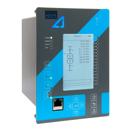
Page 13: Device User Int Vice User Interface Erface
5. Eight (8) buttons for device local programming: the four navigation arrows and the E E nt nter er button in the middle, as well as the Home Home, the Back Back and the password activation buttons. 6. One (1) RJ-45 Ethernet port for device configuration. © Arcteq Relays Ltd IM00027... -
Page 14: Local Panel Structure
Home Home and the password activation buttons). 6. Twelve (12) freely configurable function buttons (F1…F12). Each button has a freely configurable LED (red, orange, green). 7. One (1) RJ-45 Ethernet port for device configuration. © Arcteq Relays Ltd IM00027... -
Page 15: Mimic And Main Menu
Please note that the available quick display carousel view might be different if you have changed the view with AQtivate's Carousel Designer tool. Figure. 3.2.1 - 3. Basic navigation (general). © Arcteq Relays Ltd IM00027... -
Page 16: Navigation In The Main Configuration Menus
The General main menu is divided into two submenus: the Device info tab presents the information of the device, while the Function comments tab allows you to view all comments you have added to the functions. © Arcteq Relays Ltd IM00027... - Page 17 3 Device user interface A A Q Q -T216 -T216 3.3 General menu Instruction manual Version: 2.09 Figure. 3.3 - 5. General menu structure. Device info Figure. 3.3 - 6. Device info. © Arcteq Relays Ltd IM00027...
- Page 18 If set to 0 s, this feature is not in use. 0: - When activated, all LEDs are lit up. LEDs with LED test 0: - 1: Activated multiple possible colors blink each color. © Arcteq Relays Ltd IM00027...
- Page 19 Monitor profile Function comments Function comments displays notes of each function that has been activated in the Protection, Control and Monitoring menu. Function notes can be edited by the user. Figure. 3.3 - 7. Function comments. © Arcteq Relays Ltd IM00027...
-
Page 20: Protection Menu
The Protection main menu includes the Stage activation submenu as well as the submenus for all the various protection functions, categorized under the following modules: "Arc protection", "Current", "Voltage", "Frequency", "Sequence" and "Supporting" (see the image below). The available functions depend on the device type in use. © Arcteq Relays Ltd IM00027... - Page 21 For example, the I> (overcurrent) protection stage can be found in the "Current" module, whereas the U< (undervoltage) protection stage can be found in the "Voltage" module. Figure. 3.4 - 10. Submenus for Stage activation. © Arcteq Relays Ltd IM00027...
- Page 22 Figure. 3.4 - 11. Accessing the submenu of an individual activated stage. Each protection stage and supporting function has five sections in their stage submenus: "Info", "Settings", " Registers", "I/O" and "Events". Figure. 3.4 - 12. Info. © Arcteq Relays Ltd IM00027...
- Page 23 Voltage and current transformers nominal values can be set at Measurement → Transformers . • Delay type and operating time delay settings are described in detail in General properties of a protection function chapter. © Arcteq Relays Ltd IM00027...
- Page 24 Data included in the register depend on the protection function. You can clear the the operation register by choosing "Clear registers" → "Clear". "General event register" stores the event generated by the stage. These general event registers cannot be cleared. © Arcteq Relays Ltd IM00027...
- Page 25 "Blocking input control" allows you to block stages. The blocking can be done by using any of the following: • digital inputs • logical inputs or outputs • the START, TRIP or BLOCKED information of another protection stage • object status information. © Arcteq Relays Ltd IM00027...
-
Page 26: Control Menu
, for configuring the objects ( Objects) , for setting the various control functions ( Control functions) , and for configuring the inputs and outputs ( Device I/O) . The available control functions depend on the model of the device in use. © Arcteq Relays Ltd IM00027... - Page 27 • F F or orce se ce set t ting gr ting group change oup change: this setting allows the activation of a setting group at will (please note that Force SG change enable must be "Enabled"). © Arcteq Relays Ltd IM00027...
- Page 28 Each activated object is visible in the Objects submenu. By default all objects are disabled unless specifically activated in the Controls → Controls enabled submenu. Each active object has four sections in their submenus: "Settings", "Application control" ("App contr"), "Registers" and "Events". These are described in further detail below. © Arcteq Relays Ltd IM00027...
- Page 29 A request is considered to have failed when the object does not change its status as a result of that request. • C C lear sta lear statistics tistics: statistics can be cleared by choosing "Clear statistics" and then "Clear". © Arcteq Relays Ltd IM00027...
- Page 30 By default, the access level is set to "Configurator". • You can use digital inputs to control the object locally or remotely. Remote controlling via the bus is configured on the protocol level. © Arcteq Relays Ltd IM00027...
- Page 31 Object blocking is done in the "Blocking input control" subsection. It can be done by any of the following: digital inputs, logical inputs or outputs, object status information as well as stage starts, trips or blocks. Figure. 3.5 - 24. Registers section. © Arcteq Relays Ltd IM00027...
- Page 32 In the image series below, the user has activated three control functions. The user accesses the list of activated control stages through the "Control functions" module, and selects the control function for further inspection. Figure. 3.5 - 26. Control functions submenu. © Arcteq Relays Ltd IM00027...
- Page 33 While the function is activated and disabled in the Control → Controls enabled submenu, you can disable the function through the "Info" section (the [function name] mode at the top of the section). Figure. 3.5 - 28. Settings section. © Arcteq Relays Ltd IM00027...
- Page 34 Data included in the register depend on the control function. You can clear the the operation register by choosing "Clear registers" → "Clear". "General event register" stores the event generated by the stage. These general event registers cannot be cleared. © Arcteq Relays Ltd IM00027...
- Page 35 "Blocking input control" allows you to block stages. The blocking can be done by using any of the following: • digital inputs. • logical inputs or outputs. • the START, TRIP or BLOCKED information of another protection stage. • object status information. © Arcteq Relays Ltd IM00027...
- Page 36 Mimic Indicator", "Logic signals" and "GOOSE matrix". Please note that digital inputs, logic outputs, protection stage status signals (START, TRIP, BLOCKED, etc.) as well as object status signals can be connected to an output relay or to LEDs in the "Device I/O matrix" section. © Arcteq Relays Ltd IM00027...
- Page 37 "Event masks" subsection you can determine which events are masked –and therefore recorded into the event history– and which are not. Figure. 3.5 - 34. Digital outputs section. All settings related to digital outputs can be found in the "Digital outputs" section. © Arcteq Relays Ltd IM00027...
- Page 38 LED quick displays and the matrices. You can also modify the color of the LED ("LED color settings") between green and yellow; by default all LEDs are green. © Arcteq Relays Ltd IM00027...
- Page 39 These signals can be used in a variety of situations, such as for controlling the logic program, for function blocking, etc. You can name each switch and set the access level to determine who can control the switch. © Arcteq Relays Ltd IM00027...
- Page 40 Logical output signals can be used as the end result of a logic that has been built in the AQtivate 200 setting tool. The end result can then be connected to a digital output or a LED in the matrix, block functions and much more. © Arcteq Relays Ltd IM00027...
-
Page 41: Communication Menu
Communication → Connections submenu. As a standard, the devices support the following communication protocols: • NTP • IEC 61850 • Modbus/TCP • Modbus/RTU • IEC-103 • IEC -101/104 • SPA • DNP3 • ModbusIO. © Arcteq Relays Ltd IM00027... - Page 42 When communicating with a device via the front Ethernet port connection, the IP address is always 192.168.66.9. SERIAL COM1 & COM2 SERIAL COM1 & COM2 SERIAL COM1 and SERIAL COM2 are reserved for serial communication option cards. They have the same settings as the RS-485 port. © Arcteq Relays Ltd IM00027...
- Page 43 • DNP3: supports both serial and Ethernet communication. • ModbusIO: used for connecting external devices like ADAM RTD measurement units. NOTICE! TICE! Please refer to the "Communication" chapter for a more detailed text on the various communication options. © Arcteq Relays Ltd IM00027...
-
Page 44: Measurement Menu
Transformers menu is used for setting up the measurement settings of available current transformer modules or voltage transformer modules. Some unit types have more than one CT or VT module. Some unit types like AQ-S214 do not have current or voltage transformers at all. © Arcteq Relays Ltd IM00027... - Page 45 The CT module submenu also displays additional information such as CT scaling factors and per-unit scaling factors. Frequency Figure. 3.7 - 46. Frequency submenu. © Arcteq Relays Ltd IM00027...
- Page 46 (IL1, IL2, IL3) as well as the two residual currents (I01, I02); each component can be displayed as absolute or percentage values, and as primary or secondary amperages or in per-unit values. © Arcteq Relays Ltd IM00027...
-
Page 47: Monitoring Menu
( Disturbance REC ) and accessing the device diagnostics ( Device diagnostics ). The available monitoring functions depend on the type of the device in use. Figure. 3.8 - 49. Monitoring menu view. © Arcteq Relays Ltd IM00027... - Page 48 Configuring monitor functions is very similar to configuring protection and control stages. They, too, have the five sections that display information ("Info"), set the parameters ("Settings"), show the inputs and outputs ("I/O") and present the events and registers ("Events" and "Registers"). © Arcteq Relays Ltd IM00027...
- Page 49 • "Pretriggering time" can be selected between 0.1…15.0 s. • The device can record up to 20 (20) analog channels that can be selected from the twenty (20) available channels. Every measured current or voltage signal can be selected to be recorded. © Arcteq Relays Ltd IM00027...
-
Page 50: Configuring User Levels And Their Passwords
L L ock ock button in the device's HMI and set the desired passwords for the different user levels. NOTICE! TICE! Passwords can only be set locally in an HMI. © Arcteq Relays Ltd IM00027... - Page 51 As mentioned above, the access level of the different user levels is indicated by the number of stars. The required access level to change a parameter is indicated with a star (*) symbol if such is required. As a general rule the access levels are divided as follows: © Arcteq Relays Ltd IM00027...
- Page 52 • Super user: Can change any setting and can operate breakers and other equipment. NOTICE! TICE! Any user level with a password automatically locks itself after half an hour (30 minutes) of inactivity. © Arcteq Relays Ltd IM00027...
-
Page 53: Functions Unctions
Instruction manual Version: 2.09 4 Functions 4.1 Functions included in AQ-T216 The AQ-T216 transformer protection relay includes the following functions as well as the number of stages in those functions. Table. 4.1 - 4. Protection functions of AQ-T216. Name (number of... -
Page 54: Measurements
Indicator object monitoring (5 indicators available) CLPU CLPU Cold load pick-up Programmable control switch mA output Milliampere output control Table. 4.1 - 6. Monitoring functions of AQ-T216. Name ANSI Description CTS (2) Current transformer supervision Disturbance recorder Circuit breaker wear monitor... - Page 55 For the measurements to be correct the user needs to ensure that the measurement signals are connected to the correct inputs, that the current direction is connected correctly, and that the scaling is set correctly. © Arcteq Relays Ltd IM00027...
- Page 56 CT ratings and the transformer nominal current. Note that S1 is always connected to an odd connector regardless of the CT direction. The CT direction is selected in the settings of the transformer differential protection function. © Arcteq Relays Ltd IM00027...
- Page 57 TrafoModule → Idx> [87T,87N] → Settings ). This way the direction of the measured currents are checked correctly from the device's perspective. The following table presents the initial data of the connection as well as the ratings. © Arcteq Relays Ltd IM00027...
- Page 58 As seen in the image above, device calculates both the HV side nominal current (669.2 A) and the LV side nominal current (5,888.97 A). The nominal current calculations are done according to the following formulas: The HV and LV side nominal current can also be calculated in per unit values as follows: © Arcteq Relays Ltd IM00027...
- Page 59 CT ratings and the transformer nominal current. Note that S1 is always connected to an odd connector regardless of the CT direction. The CT direction is selected in the settings of the transformer differential protection function. © Arcteq Relays Ltd IM00027...
- Page 60 [87T,87N] → Settings ). The difference with the first application is that here the CTs point towards the protected object instead of pointing through it. The following table presents the initial data of the connection as well as the ratings. © Arcteq Relays Ltd IM00027...
- Page 61 CTs are checked. In Application 2 it is necessary to inject higher amplitudes to the CTs via the secondary injection tool in order to reach the nominal currents. See the example calculation below: © Arcteq Relays Ltd IM00027...
- Page 62 CT scaling factor P/S between the primary current and the secondary current. A feedback value; the calculated scaling factor that is the ratio CT scaling factor NOM between the set primary current and the set nominal current. © Arcteq Relays Ltd IM00027...
- Page 63 The following measurements are available in the measured current channels. Table. 4.2.1 - 12. Per-unit phase current measurements. Name Unit Range Step Description Phase current 0.000…1 The RMS current measurement (in p.u.) from each of the × In 0.001 250.000 phase current channels. ("Pha.curr.ILx") © Arcteq Relays Ltd IM00027...
- Page 64 The RMS current measurement (in p.u.) from the residual current I0x × In 0.001 250.000 current channel I01 or I02. ("Res.curr.I0x") 0.000…1 The RMS current measurement (in p.u.) from the calculated Calculated I0 × In 0.001 250.000 I0 current channel. © Arcteq Relays Ltd IM00027...
- Page 65 Unit Range Step Description Residual current angle I0x The residual current angle measurement from the I01 or 0.000…360.000 0.001 ("Res.curr.angle I02 current input. I0x") Calculated I0 angle 0.000…360.000 0.001 The calculated residual current angle measurement. © Arcteq Relays Ltd IM00027...
- Page 66 Secondary negative sequence current The secondary measurement from the calculated 0.000…300.000 0.001 ("Sec.Negative negative sequence current. sequence curr.") Secondary zero sequence current The secondary measurement from the calculated 0.000…300.000 0.001 ("Sec.Zero sequence zero sequence current. curr.") © Arcteq Relays Ltd IM00027...
-
Page 67: Frequency Tracking And Scaling
The benefit of frequency tracking is that the measurements are within a pre-defined accuracy range even when the fundamental frequency of the power system changes. Frequency independent current and voltage measurement accuracy is achieved with algorithms specified in patent US 10,809,287. © Arcteq Relays Ltd IM00027... - Page 68 FFT calculation always has a whole power cycle in the buffer. The measurement accuracy is further improved by Arcteq's patented calibration algorithms that calibrate the analog channels against eight (8) system frequency points for both magnitude and angle.
- Page 69 The second reference source for frequency 2: CT2IL2 1: CT1IL2 reference 2 tracking. 3: VT1U2 4: VT2U2 0: None 1: CT1IL3 Frequency 2: CT2IL3 1: CT1IL3 The third reference source for frequency tracking. reference 3 3: VT1U3 4: VT2U3 © Arcteq Relays Ltd IM00027...
- Page 70 Alg f avg 0.000…75.000Hz 0.001Hz - tracked frequencies and U4 voltage channel samples. 0: One f measured System 1: Two f Displays the amount of frequencies that are measured measured measured. frequency 2: Three f measured © Arcteq Relays Ltd IM00027...
-
Page 71: General Menu
The order code identification of the unit. System phase rotating order at The selected system phase rotating order. Can be changed with parameter the moment "System phase rotating order". UTC time The UTC time value which the device's clock uses. © Arcteq Relays Ltd IM00027... - Page 72 When a reset command is given, the parameter 1: Reset automatically returns back to "-". 0: Disabled Enables the measurement recorder tool, further Measurement recorder 0: Disabled 1: Enabled configured in Tools → Misc → Measurement recorder. © Arcteq Relays Ltd IM00027...
-
Page 73: Protection Functions
4.4.1 General properties of a protection function The following flowchart describes the basic structure of any protection function. The basic structure is composed of analog measurement values being compared to the pick-up values and operating time characteristics. © Arcteq Relays Ltd IM00027... - Page 74 4 Functions Instruction manual 4.4 Protection functions Version: 2.09 The protection function is run in a completely digital environment with a protection CPU microprocessor which also processes the analog signals transformed into the digital form. © Arcteq Relays Ltd IM00027...
- Page 75 Figure. 4.4.1 - 62. Pick up and reset. The pick-up activation of the function is not directly equal to the START signal generation of the function. The START signal is allowed if a blocking condition is not active. © Arcteq Relays Ltd IM00027...
- Page 76 (independent time characteristics). • Inverse definite minimum time (IDMT): activates the trip signal after a time which is in relation to the set pick-up value X and the measured value X (dependent time characteristics). © Arcteq Relays Ltd IM00027...
- Page 77 Selects whether the delay curve series for an IDMT operation follows either IEC or IEEE/ANSI standard Delay curve 0: IEC defined characteristics. 0: IEC series 1: IEEE This setting is active and visible when the "Delay type" parameter is set to "IDMT". © Arcteq Relays Ltd IM00027...
- Page 78 "Param". Defines the Constant C for IEEE characteristics. This setting is active and visible when the "Delay type" 0.0000…250.0000 0.0001 0.0200 parameter is set to "IDMT" and the "Delay characteristic" parameter is set to "Param". © Arcteq Relays Ltd IM00027...
- Page 79 = Operating delay (s) t = Operating delay (s) k = Time dial setting k = Time dial setting = Measured maximum current = Measured maximum current = Pick-up setting = Pick-up setting © Arcteq Relays Ltd IM00027...
- Page 80 1: Yes even if the pick-up element is reset. release time The behavior of the stages with different release time configurations are presented in the figures below. Figure. 4.4.1 - 66. No delayed pick-up release. © Arcteq Relays Ltd IM00027...
- Page 81 4.4 Protection functions Instruction manual Version: 2.09 Figure. 4.4.1 - 67. Delayed pick-up release, delay counter is reset at signal drop-off. Figure. 4.4.1 - 68. Delayed pick-up release, delay counter value is held during the release time. © Arcteq Relays Ltd IM00027...
-
Page 82: Non-Directional Overcurrent Protection (I>; 50/51)
The blocking signal and the setting group selection control the operating characteristics of the function during normal operation, i.e. the user or user-defined logic can change function parameters while the function is running. © Arcteq Relays Ltd IM00027... - Page 83 1 ms. The function also provides a resettable cumulative counter for the START, TRIP and BLOCKED events. The following figure presents a simplified function block diagram of the non-directional overcurrent function. Figure. 4.4.2 - 70. Simplified function block diagram of the I> function. © Arcteq Relays Ltd IM00027...
- Page 84 Table. 4.4.2 - 34. General settings of the function. Name Range Default Description Disabled Setting control Activating this parameter allows changing the pick-up level of the from comm bus Disabled protection stage via SCADA. Allowed © Arcteq Relays Ltd IM00027...
- Page 85 Pick-up setting 0.10…50.00×I 0.01×I 1.20×I The pick-up activation of the function is not directly equal to the START signal generation of the function. The START signal is allowed if the blocking condition is not active. © Arcteq Relays Ltd IM00027...
- Page 86 START signal is generated and the function proceeds to the time characteristics calculation. Table. 4.4.2 - 37. Internal inrush harmonic blocking settings. Name Range Step Default Description Inrush harmonic blocking 0: No Enables and disables the 2 0: No (internal-only trip) 1: Yes harmonic blocking. © Arcteq Relays Ltd IM00027...
- Page 87 Block ON NOC1 Block OFF NOC1 Phase A Start ON NOC1 Phase A Start OFF NOC1 Phase B Start ON NOC1 Phase B Start OFF NOC1 Phase C Start ON NOC1 Phase C Start OFF © Arcteq Relays Ltd IM00027...
- Page 88 Phase B Trip OFF NOC2 Phase C Trip ON NOC2 Phase C Trip OFF NOC3 Start ON NOC3 Start OFF NOC3 Trip ON NOC3 Trip OFF NOC3 Block ON NOC3 Block OFF NOC3 Phase A Start ON © Arcteq Relays Ltd IM00027...
- Page 89 NOC4 Phase C Start OFF NOC4 Phase A Trip ON NOC4 Phase A Trip OFF NOC4 Phase B Trip ON NOC4 Phase B Trip OFF NOC4 Phase C Trip ON NOC4 Phase C Trip OFF © Arcteq Relays Ltd IM00027...
-
Page 90: Non-Directional Earth Fault Protection (I0>; 50N/51N)
(3) output signals. In the instant operating mode the function outputs START and TRIP events simultaneously with an equivalent time stamp. The time stamp resolution is 1 ms. The function also provides a resettable cumulative counter for the START, TRIP and BLOCKED events. © Arcteq Relays Ltd IM00027... - Page 91 START or TRIP event. General settings The following general settings define the general behavior of the function. These settings are static i.e. it is not possible to change them by editing the setting group. © Arcteq Relays Ltd IM00027...
- Page 92 The relay's Info page displays useful, real-time information on the state of the protection function. It is accessed either through the relay's HMI display, or through the setting tool software when it is connected to the relay and its Live Edit mode is active. © Arcteq Relays Ltd IM00027...
- Page 93 The blocking of the function causes an HMI display event and a time-stamped blocking event with information of the startup current values and its fault type to be issued. © Arcteq Relays Ltd IM00027...
- Page 94 Start OFF NEF2 Trip ON NEF2 Trip OFF NEF2 Block ON NEF2 Block OFF NEF3 Start ON NEF3 Start OFF NEF3 Trip ON NEF3 Trip OFF NEF3 Block ON NEF3 Block OFF NEF4 Start ON © Arcteq Relays Ltd IM00027...
-
Page 95: Negative Sequence Overcurrent/ Phase Current Reversal/ Current Unbalance Protection (I2>; 46/46R/46L)
IEC and ANSI standard time delays as well as custom parameters. The operational logic consists of the following: • input magnitude selelction • input magnitude processing • threshold comparator • block signal check • time delay characteristics © Arcteq Relays Ltd IM00027... - Page 96 Time base Positive sequence current magnitude 5 ms Negative sequence current magnitude 5 ms Zero sequence current magnitude 5 ms I1 ANG Positive sequence current angle 5 ms I2 ANG Negative sequence current angle 5 ms © Arcteq Relays Ltd IM00027...
- Page 97 Pick-up setting for I2/I1 mode 1…200% 0.01% The pick-up activation of the function is not directly equal to the START signal generation of the function. The START signal is allowed if the blocking condition is not active. © Arcteq Relays Ltd IM00027...
- Page 98 Both IEC and IEEE/ANSI standard characteristics as well as user settable parameters are available for the IDMT operation. Unique to the current unbalance protection is the availability of the “Curve2” delay which follows the formula below: © Arcteq Relays Ltd IM00027...
- Page 99 OFF for messages in the main event buffer. The function offers four (4) independent stages; the events are segregated for each stage operation. The triggering event of the function (START, TRIP or BLOCKED) is recorded with a time stamp and with process data values. © Arcteq Relays Ltd IM00027...
- Page 100 The function registers its operation into the last twelve (12) time-stamped registers. The register of the function records the ON event process data for START, TRIP or BLOCKED. The table below presents the structure of the function's register content. © Arcteq Relays Ltd IM00027...
-
Page 101: Harmonic Overcurrent Protection (Ih>; 50H/51H/68H)
START and TRIP events simultaneously with an equivalent time stamp. The time stamp resolution is 1 ms. The function also provides a resettable cumulative counter for the START, TRIP and BLOCKED events. The following figure presents a simplified function block diagram of the non-directional harmonic overcurrent function. © Arcteq Relays Ltd IM00027... - Page 102 The magnitudes (RMS) of phase L1 (A) current components: - Fundamental harmonic harmonic harmonic harmonic harmonic IL1FFT 5 ms harmonic harmonic - 11 harmonic - 13 harmonic - 15 harmonic - 17 harmonic - 19 harmonic. © Arcteq Relays Ltd IM00027...
- Page 103 The magnitudes (RMS) of residual I0 current components: - Fundamental harmonic harmonic harmonic harmonic harmonic I01FFT 5 ms harmonic harmonic - 11 harmonic - 13 harmonic - 15 harmonic - 17 harmonic - 19 harmonic. © Arcteq Relays Ltd IM00027...
- Page 104 General menu. Blocked Ih> 1: Side 1 Defines which current measurement module is used by the function. measurement 1: Side 1 Visible if the unit has more than one current measurement module. 2: Side 2 side © Arcteq Relays Ltd IM00027...
- Page 105 (in single, dual or all phases) it triggers the pick-up operation of the function. Table. 4.4.5 - 55. Pick-up settings. Name Range Step Default Description Pick-up setting 0.05…2.00×I 0.01×I 0.20×I (per unit monitoring) Pick-up setting Ih/IL 5.00…200.00% 0.01% 20.00% (percentage monitoring) © Arcteq Relays Ltd IM00027...
- Page 106 This function supports definite time delay (DT) and inverse definite minimum time delay (IDMT). For detailed information on these delay types please refer to the chapter "General properties of a protection function" and its section "Operating time characteristics for trip and reset". © Arcteq Relays Ltd IM00027...
- Page 107 Start ON HOC3 Start OFF HOC3 Trip ON HOC3 Trip OFF HOC3 Block ON HOC3 Block OFF HOC4 Start ON HOC4 Start OFF HOC4 Trip ON HOC4 Trip OFF HOC4 Block ON HOC4 Block OFF © Arcteq Relays Ltd IM00027...
-
Page 108: Circuit Breaker Failure Protection (Cbfp; 50Bf/52Bf)
• block signal check • time delay characteristics • output processing. The inputs of the function are the following: • operating mode selections • setting parameters • digital input signals • measured and pre-processed current magnitudes. © Arcteq Relays Ltd IM00027... - Page 109 RMS measurement of phase L3 (C) current I01RMS RMS measurement of residual input I01 I02RMS RMS measurement of residual input I02 I0Calc Calculated residual current from the phase current inputs DOIN Monitors digital output relay status DIIN Monitors digital input status © Arcteq Relays Ltd IM00027...
- Page 110 I value. The setting value is common for all measured phases. When the I exceeds the I value (in single, dual or all phases) it triggers the pick-up operation of the function. © Arcteq Relays Ltd IM00027...
- Page 111 The relay's Info page displays useful, real-time information on the state of the protection function. It is accessed either through the relay's HMI display, or through the setting tool software when it is connected to the relay and its Live Edit mode is active. © Arcteq Relays Ltd IM00027...
- Page 112 CBFP starts the timer. This setting defines how long the CBFP 0.000…1800.000s 0.005s 0.200s starting condition has to last before the CBFP signal is activated. The following figures present some typical cases of the CBFP function. © Arcteq Relays Ltd IM00027...
- Page 113 The retrip is wired from its own device output contact in parallel with the circuit breaker's redundant trip coil. The CBFP signal is normally wired from its device output contact to the incomer breaker. Below are a few operational cases regarding the various applications. © Arcteq Relays Ltd IM00027...
- Page 114 CBFP signal to the incomer breaker. If the primary protection function clears the fault, both counters (RETRIP and CBFP) are reset as soon as the measured current is below the threshold settings. © Arcteq Relays Ltd IM00027...
- Page 115 (RETRIP and CBFP) are reset as soon as the measured current is below the threshold settings or the tripping signal is reset. This configuration allows the CBFP to be controlled with current-based functions alone, and other function trips can be excluded from the CBFP functionality. © Arcteq Relays Ltd IM00027...
- Page 116 This configuration allows the CBFP to be controlled with current-based functions alone, with added security from current monitoring. Other function trips can also be included in the CBFP functionality. © Arcteq Relays Ltd IM00027...
- Page 117 Probably the most common application is when the device's trip output controls the circuit breaker trip coil, while one dedicated CBFP contact controls the CBFP function. Below are a few operational cases regarding the various applications and settings of the CBFP function. © Arcteq Relays Ltd IM00027...
- Page 118 CBFP signal is sent to the incomer breaker. If the primary protection function clears the fault, the counter for CBFP resets as soon as the measured current is below the threshold settings. © Arcteq Relays Ltd IM00027...
- Page 119 The time delay counter for CBFP is reset as soon as the measured current is below the threshold settings or the tripping signal is reset. This configuration allows the CBFP to be controlled by current-based functions alone, and other function trips can be excluded from the CBFP functionality. © Arcteq Relays Ltd IM00027...
- Page 120 This configuration allows the CBFP to be controlled by current-based functions alone, with added security from current monitoring. Other function trips can also be included to the CBFP functionality. © Arcteq Relays Ltd IM00027...
- Page 121 A A Q Q -T216 -T216 4.4 Protection functions Instruction manual Version: 2.09 Device configuration as a dedicated CBFP unit Figure. 4.4.6 - 84. Wiring diagram when the device is configured as a dedicated CBFP unit. © Arcteq Relays Ltd IM00027...
- Page 122 ON, OFF, or both. The events triggered by the function are recorded with a time stamp and with process data values. Table. 4.4.6 - 66. Event messages. Event block name Event names CBF1 Start ON CBF1 Start OFF © Arcteq Relays Ltd IM00027...
-
Page 123: Low-Impedance Or High-Impedance Restricted Earth Fault/ Cable End Differential Protection (I0D>; 87N)
The restricted earth fault function constantly monitors phase currents and selected residual current instant values as well as calculated bias current and differential current magnitudes. © Arcteq Relays Ltd IM00027... - Page 124 The user can select inputs I01 or I02 for residual current measurement. Please note that when the function is in cable end differential mode, the difference is only calculated when the measured I0 current is available. © Arcteq Relays Ltd IM00027...
- Page 125 CED mode. Operating characteristics The current-dependent pick-up and activation of the function are controlled by setting parameters, which define the current calculating method used as well as the operating characteristics. © Arcteq Relays Ltd IM00027...
- Page 126 Setting for the second slope of the differential Slope 2 0.01…250.00% 0.01% 40.00% characteristics. Figure. 4.4.7 - 87. "I0 direction" parameter must be set to "Subtract" when current transformers are facing the same direction. © Arcteq Relays Ltd IM00027...
- Page 127 Figure. 4.4.7 - 89. Differential characteristics for the I0d> function with default settings. The equations for the differential characteristics are the following: Figure. 4.4.7 - 90. Differential current (the calculation is based on user-selected inputs and direction). © Arcteq Relays Ltd IM00027...
- Page 128 The variables the user can set are binary signals from the system. The blocking signal needs to reach the device minimum of 5 ms before the set operating delay has passed in order for the blocking to activate in time. The following figures present some typical applications for this function. © Arcteq Relays Ltd IM00027...
- Page 129 CTs are still within the promised 5P class (which is probably the most common CT accuracy class). When the current natural unbalance is compensated in this situation, the differential settings may be set to be more sensitive and the natural unbalance does not, therefore, affect the calculation. © Arcteq Relays Ltd IM00027...
- Page 130 During an outside earth fault the circulating residual current in the faulty phase winding does not cause a trip because the comparison of the measured starpoint current and the calculated residual current differential is close to zero. © Arcteq Relays Ltd IM00027...
- Page 131 If the fault is located inside of the transformer and thus inside of the protection area, the function catches the fault with high sensitivity. Since the measured residual current now flows in the opposite direction than in the outside fault situation, the measured differential current is high. © Arcteq Relays Ltd IM00027...
- Page 132 TRIP-activated and BLOCKED signals. The user can select which event messages are stored in the main event buffer: ON, OFF, or both. The events triggered by the function are recorded with a time stamp and with process data values. © Arcteq Relays Ltd IM00027...
-
Page 133: Transformer Status Monitoring
• LV side inrush • normal load • overloading • heavy overloading. These signals can be used in indication or in logic programming, and they are the basis for the events the function generates (if so chosen). © Arcteq Relays Ltd IM00027... - Page 134 The function's outputs are dependent on the set transformer data because the measured currents (in p.u.) are related to the transformer nominal values. The following diagram presents the function's outputs in various situations. Figure. 4.4.8 - 98. Activation of the function's outputs. © Arcteq Relays Ltd IM00027...
- Page 135 The transformer's short-circuit Transformer impedance in percentages. 0.01…25.00% 0.01% 3.00% Info Used for calculating short-circuit current. The transformer's nominal Transformer frequency. Used for calculating 10…75Hz 50Hz Info nom. freq. the transformer's nominal short- circuit inductance. © Arcteq Relays Ltd IM00027...
- Page 136 0: Star/Zigzag 0: Star/ monitoring or Zigzag / delta. This selection is visible 1: Delta Zigzag - transformer Delta only if the option "Manual set" is differential selected for the vector group setting. © Arcteq Relays Ltd IM00027...
- Page 137 The calculated primary current of the 0.01…250.00A 0.01A 0.00A Info current transformer's HV side secondary current. (sec) HV CT The transformer's HV side calculated nom. to TR 0.01…250.00p.u. 0.01p.u. 0.00p.u. Info nominal to the CT primary rate. nom. factor © Arcteq Relays Ltd IM00027...
- Page 138 The signal is active, when the detected current rises above the "High overcurrent" limit in detected the LV side. The signal is active when the measured current is below the "Nominal current" but above Load normal the "No load current" limit. © Arcteq Relays Ltd IM00027...
- Page 139 HV side's LV side's dd.mm.yyyy Event Phase Phase Phase Phase L1 Phase L2 Phase L2 L3 current x L1 current x L3 current x hh:mm:ss.mss name current x I current x I current x I © Arcteq Relays Ltd IM00027...
-
Page 140: Transformer Thermal Overload Protection (Tt>; 49T)
100 % indefinitely but never exceeds it. With a single time constant model the cooling of the object follows this same behavior, the reverse of the heating when the current feeding is zero. © Arcteq Relays Ltd IM00027... - Page 141 The ambient temperature compensation takes into account the set minimum and maximum temperatures and the load capacity of the protected object as well as the measured or set ambient temperature. The calculated coefficient is a linear correction factor, as the following formula shows: © Arcteq Relays Ltd IM00027...
- Page 142 Function inputs and outputs The blocking signal and the setting group selection control the operating characteristics of the function during normal operation, i.e. the user or user-defined logic can change function parameters while the function is running. © Arcteq Relays Ltd IM00027...
- Page 143 Table. 4.4.9 - 79. Measurement inputs of the TT> function. Signal Description Time base IL1TRMS TRMS measurement of phase L1 (A) current 5 ms IL2TRMS TRMS measurement of phase L2 (B) current 5 ms IL3TRMS TRMS measurement of phase L3 (C) current 5 ms © Arcteq Relays Ltd IM00027...
- Page 144 It is also possible to reset the reset 0.0…150.0% 0.1% 60.0% thermal element. default theta This parameter can be used when testing the function to manually set the current thermal cap to any value. © Arcteq Relays Ltd IM00027...
- Page 145 "Linear est." Amb. The temperature reference points for the user-settable temp. ref. -50.0…500.0deg 0.1deg 15deg ambient temperature coefficient curve. This setting is visible 1...10 if "Ambient lin. or curve" is set to "Set curve". © Arcteq Relays Ltd IM00027...
- Page 146 1: Enabled Disabled Inhibit TT> Inhibit 0.0…150.0% 0.1% INHIBIT activation threshold. level Enable 0: Disabled TT> Enabling/disabling the TRIP signal and the I/O. 1: Enabled Disabled Trip TT> Trip 0.0…150.0% 0.1% 100% TRIP activation threshold. level © Arcteq Relays Ltd IM00027...
- Page 147 TT> 1: Service Indicates if SF setting has been set wrong and the actually used setting is 1.0. Visible Setting factor set only when there is a setting fault. alarm fault. Override to © Arcteq Relays Ltd IM00027...
- Page 148 - TT> Alarm 2 time to rel.: the time to reach theta while staying below the Alarm 2 limit during cooling - TT> Inhibit time to rel.: the time to reach theta while staying below the Inhibit limit during cooling © Arcteq Relays Ltd IM00027...
- Page 149 ON event process data for TRIP, BLOCKED, etc. signals. The table below presents the structure of the function's register content. Table. 4.4.9 - 88. Register content. Name Description Date and time dd.mm.yyyy hh:mm:ss.mss Event Event name Time to reach 100 % theta seconds © Arcteq Relays Ltd IM00027...
-
Page 150: Generator/Transformer Differential Protection (Idb>/Idi>/I0Dhv>/I0Dlv>; 87T/87N/87G)
This function can also be used for protecting generators. Figure. 4.4.10 - 102. Differential protection function can be used for protecting transformers, generators and both at the same time. © Arcteq Relays Ltd IM00027... - Page 151 If the transformer is oil-insulated, oil level monitoring should be applied. © Arcteq Relays Ltd IM00027...
- Page 152 (such as in the bus or in the cables connected to the transformer). Faults of this type are easily repaired and the transformer can be re- energized soon after the fault has bee cleared. © Arcteq Relays Ltd IM00027...
- Page 153 • the ratios and properties of the transformers HV and LV sides. This chapter shows the setting and the principle of transformer differential protection step by step. Figure. 4.4.10 - 103. Transformer and its components forming the differential zone. © Arcteq Relays Ltd IM00027...
- Page 154 Let us further say the HV side current transformers are 150/5 A and the LV side current transformers are 1200/5 A. The primary side factor (p.u.) and current are then calculated as follows: Then, the secondary side factor (p.u.) and current are calculated as follows: © Arcteq Relays Ltd IM00027...
- Page 155 LV side is leading 30 degrees; '5' and '7' are just the other ends of the windings thus causing a 180-degree difference between the '1' and '11' clock numbers. The following example explains transformer current vectors and what a connection might look like. © Arcteq Relays Ltd IM00027...
- Page 156 A A Q Q -T216 -T216 4 Functions Instruction manual 4.4 Protection functions Version: 2.09 Figure. 4.4.10 - 106. Yd1 transformer's internal connection (in theory). © Arcteq Relays Ltd IM00027...
- Page 157 Y-connected vector diagram. The images below present the differential algorithm itself (one calculating formula for each phase difference); first the "subtract" formulas, then the "add" formulas. Selection is based on the CT connections. © Arcteq Relays Ltd IM00027...
- Page 158 A A Q Q -T216 -T216 4 Functions Instruction manual 4.4 Protection functions Version: 2.09 Figure. 4.4.10 - 108. "Subtract" formula. Figure. 4.4.10 - 109. "Add" formula. Figure. 4.4.10 - 110. CTs' starpoints requiring the "Add" mode. © Arcteq Relays Ltd IM00027...
- Page 159 Next, these two formulas are combined in a graph: the x-axis presents the measured differential current, and the y-axis presents the calculated bias current. The following graph shows the differential function characteristic, both biased and non-biased. © Arcteq Relays Ltd IM00027...
- Page 160 ). It is the basic sensitivity limit: when the measured differential current is below this limit, the d>pick-up transformer still operates normally and the protection does not trigger. In other words, the pick-up current setting must be higher than the combination of all the normal operation factors that cause differential currents. © Arcteq Relays Ltd IM00027...
- Page 161 3) Relay measurement accuracy (primary and secondary) (RE The relay measurement error is below 0.5 %, its optional accuracy below 0.2 % per measurement channel: the combined value for both sides is either 1 % or 0.4 %. © Arcteq Relays Ltd IM00027...
- Page 162 This causes a difference in the nominal current condition, which can be noticed as a differential current in the relay. Usually tap changer positions are presented as deviation steps for the secondary voltage to both positive and negative direction from the center (see the second image below). © Arcteq Relays Ltd IM00027...
- Page 163 If there is no tap changer, the maximum uncertainty can be calculated sufficiently enough by summing the maximum inaccuracies of the CTs on the HV and LV sides. © Arcteq Relays Ltd IM00027...
- Page 164 Slope 1 is calculated by using the transformer and CT nominal values in the maximum full load (Turnpoint 2) of the transformer with highest possible differential current causing tap position. Generally the Slope 1 setting is calculated as follows: © Arcteq Relays Ltd IM00027...
- Page 165 CTs differently (starpoint towards or away from the transformer). Thus, the differential current is always calculated as follows: © Arcteq Relays Ltd IM00027...
- Page 166 Therefore, the differential current is the following: If the Maximum mode is used for biasing (due to a single end fault), the bias current is the same as the differential current. Therefore, the Slope 2 setting is calculated as follows: © Arcteq Relays Ltd IM00027...
- Page 167 CTs, the connection between the CTs, as well as the cross-section and material of the wires. Let us begin with the burden the wiring causes to the relay, and calculate the resistance in a conductor: © Arcteq Relays Ltd IM00027...
- Page 168 It is recommended that you use the worst-case scenario as the basis for calculating the CT burden. In most cases these +75 ºC values are sufficient. If the ambient temperature in your application is higher than +75 ºC, the resistance should be calculated for that specific temperature. © Arcteq Relays Ltd IM00027...
- Page 169 If the CTs have the possibility to saturate (that is, the calculated through fault current is bigger than the ALF on either CT side), the setting of the instant stage must be set high enough so that it does not operate on through fault saturation. © Arcteq Relays Ltd IM00027...
- Page 170 (using these same formulas) in the Transformer status monitoring (TRF) module. When everything is set up correctly in the relay and when the transformer is feeding the load with nominal power, the result should look like the following example configuration when the example settings and transformer are used. © Arcteq Relays Ltd IM00027...
- Page 171 4 Functions A A Q Q -T216 -T216 4.4 Protection functions Instruction manual Version: 2.09 Figure. 4.4.10 - 117. Example configuration for the transformer differential function. © Arcteq Relays Ltd IM00027...
- Page 172 Our example presented only one type of transformer and its properties. Another very common variation is the type of transformer where the star side (HV, LV, or both) is earthed and thus forms a route outside the differential zone (see the image below). © Arcteq Relays Ltd IM00027...
- Page 173 (in p.u.) before differential calculation and thus negates the effect of an external earth fault. Correctly selected transformer settings prevent the differential function from being tripped by out-of-zone earth faults (see the image below). © Arcteq Relays Ltd IM00027...
- Page 174 However, enabling the REF protection requires that both the phase current measurements and the starpoint current are available and can be connected to the relay's residual current channel on the corresponding (HV/LV) side measurement. © Arcteq Relays Ltd IM00027...
- Page 175 (external) earth faults, and the how a heavy fault going fully through the second biased section (Slope 2) can cause saturation in the CTs' phase currents. The recommended base settings: • Pick-up (base sensitivity): typically 5 % to 10 % of the phase current CT error (Px) © Arcteq Relays Ltd IM00027...
- Page 176 The differential relay sees the energization current as a differential current since it only flows through the primary side winding only. The saturation of the transformer core generates the 2 harmonic component which can be used to block the biased sensitive differential stage during energization. © Arcteq Relays Ltd IM00027...
- Page 177 (in amperes), the fourth graph depicts the fundamental (50 Hz) FFT- calculated currents (in amperes), and fifth graph depicts the 2 harmonic components relative to the corresponding fundamental component currents (with the 15 % setting limit). © Arcteq Relays Ltd IM00027...
- Page 178 While the results are very low compared to the magnetizing inrush current magnitudes, the differential relay would still definitely trip without the 2 harmonic blocking. The situation is the same with all of the calculted setting variations. © Arcteq Relays Ltd IM00027...
- Page 179 Figure. 4.4.10 - 123. Inrush blocking by using the 2 harmonic (relative to fundamental frequency). Figure. 4.4.10 - 124. Example of transformer magnetizing inrush currents. A conservative setting recommendation for standard type transformers: © Arcteq Relays Ltd IM00027...
- Page 180 Figure. 4.4.10 - 125. Transformer behavior in case of overvoltage caused by overexcitation. © Arcteq Relays Ltd IM00027...
- Page 181 The figures below present the system voltage and the magnitude of the 5 harmonic component (both in per-unit), absolute and scaled to the transformer nominal. © Arcteq Relays Ltd IM00027...
- Page 182 (that is, no overvoltage relays are available), this blocking can be enabled with the setting of 30...40 % with the disturbance recorder enabled. If a trip occurs as a result of overexcitation, the settings can be adjusted based on the data captured by the disturbance recorder. © Arcteq Relays Ltd IM00027...
- Page 183 6: H5block On Idx> force only when Enable stage 7: HV I0d> forcing parameter is enabled status to Normal Block On in General menu. 8: HV I0d> Trip 9: LV I0d> Block On 10: LV I0d> Trip © Arcteq Relays Ltd IM00027...
- Page 184 HV side 0: Not HV side current calculation. The grounded monitoring grounded grounded selection is visible only if the option 1: Grounded - transformer "Manual set" is selected for the vector differential group setting. © Arcteq Relays Ltd IM00027...
- Page 185 HV side. starpoint 0: IO1 monitoring 1: IO2 This setting is only visible if the option meas. - transformer "Enabled" is selected for the "Enable I0d> differential (REF) HV side" setting. © Arcteq Relays Ltd IM00027...
- Page 186 5 harmonic blocking The pick-up detection for the 2 harmonic blocking harmonic 0.01…50.00% 0.01% 15.00% stage. This setting is only visible if the "Enable harmonic blocking blocking" setting is set to "1" or "3". pick-up © Arcteq Relays Ltd IM00027...
- Page 187 Slope 2 I0d> (REF) LV side" setting is enabled. Table. 4.4.10 - 91. Calculations of the transformer differential function. Name Description L1Bias The calculated phase L1 bias current L2Bias The calculated phase L2 bias current © Arcteq Relays Ltd IM00027...
- Page 188 The TRIP output signal from the biased restricted earth fault differential stage on the LV LV I0d> Trip side The BLOCKED output signal from the biased restricted earth fault differential stage on LV I0d> Trip the LV side © Arcteq Relays Ltd IM00027...
- Page 189 DIF1 L1 5 harmonic ON DIF1 L1 5 harmonic OFF DIF1 L2 5 harmonic ON DIF1 L2 5 harmonic OFF DIF1 L3 5 harmonic ON DIF1 L3 5 harmonic OFF DIF1 HV I0d> Block ON © Arcteq Relays Ltd IM00027...
- Page 190 LV side REF bias current LV I0d> differential current LV side REF differential current LV I0d> characteristics current LV side REF maximum differential current with bias Used SG Setting group in use Ftype Detected fault type (faulty phases) © Arcteq Relays Ltd IM00027...
-
Page 191: Resistance Temperature Detectors (Rtd)
0: InternalRTD1 Selects the measurement module. 1: InternalRTD2 Internal RTD modules are option cards S1...S16 module 2: ExtModuleA InternalRTD1 installed to the relay. External modules 3: ExtModuleB are Modbus based external devices. 4: ExtModuleC © Arcteq Relays Ltd IM00027... - Page 192 There are sixteen (16) available sensor inputs in the function. An active alarm requires a valid channel measurement. It can be invalid if communication is not working or if a sensor is broken. © Arcteq Relays Ltd IM00027...
- Page 193 S4 Alarm1 OFF RTD1 S4 Alarm2 ON RTD1 S4 Alarm2 OFF RTD1 S5 Alarm1 ON RTD1 S5 Alarm1 OFF RTD1 S5 Alarm2 ON RTD1 S5 Alarm2 OFF RTD1 S6 Alarm1 ON RTD1 S6 Alarm1 OFF © Arcteq Relays Ltd IM00027...
- Page 194 S12 Alarm1 ON RTD1 S12 Alarm1 OFF RTD1 S12 Alarm2 ON RTD1 S12 Alarm2 OFF RTD1 S13 Alarm1 ON RTD1 S13 Alarm1 OFF RTD1 S13 Alarm2 ON RTD1 S13 Alarm2 OFF RTD1 S14 Alarm1 ON © Arcteq Relays Ltd IM00027...
- Page 195 S6 Meas Invalid RTD2 S7 Meas Ok RTD2 S7 Meas Invalid RTD2 S8 Meas Ok RTD2 S8 Meas Invalid RTD2 S9 Meas Ok RTD2 S9 Meas Invalid RTD2 S10 Meas Ok RTD2 S10 Meas Invalid © Arcteq Relays Ltd IM00027...
-
Page 196: Programmable Stage (Pgx>/<; 99)
The function can operate on instant or time-delayed mode. Definite time (DT) delay can be selected in the In time-delayed mode. The inputs for the function are the following: • operating mode selections • setting parameters • digital inputs and logic signals © Arcteq Relays Ltd IM00027... - Page 197 Table. 4.4.12 - 98. Other current measurements Name Description I0Z Mag Zero sequence current value (in p.u.) I0CALC Mag Calculated I0 value (in p.u.) I1 Mag Positive sequence current value (in p.u.) I2 Mag Negative sequence current value (in p.u.) © Arcteq Relays Ltd IM00027...
- Page 198 UL1 angle (degrees) UL2Ang UL2 angle (degrees) UL3Ang UL3 angle (degrees) U0Ang UL0 angle (degrees) U0CalcMag Calculated residual voltage U1 pos.seq.V Mag Positive sequence voltage U2 neg.seq.V Mag Negative sequence voltage U0CalcAng Calculated residual voltage angle (degrees) © Arcteq Relays Ltd IM00027...
- Page 199 Impedance Z L12, L23, L31, L1, L2, L3 angle Table. 4.4.12 - 102. Other impedances, resistances and reactances Name Description RSeqPri Positive Resistance R primary (Ω) XSeqPri Positive Reactance X primary (Ω) RSeqSec Positive Resistance R secondary (Ω) © Arcteq Relays Ltd IM00027...
- Page 200 Admittance Y0 secondary (mS) Y0Angle Admittance Y0 angle Table. 4.4.12 - 105. Other measurements Name Description System f. System frequency Ref f1 Reference frequency 1 Ref f2 Reference frequency 2 M Thermal T Motor thermal temperature © Arcteq Relays Ltd IM00027...
- Page 201 PSx Scaled -5 000 000...5 000 Displays measurement value after multiplying it the value set magnitude X to PSx Magnitude multiplier . © Arcteq Relays Ltd IM00027...
- Page 202 0.06s Pick-up release delay delays The pick-up activation of the function is not directly equal to the START signal generation of the function. The START signal is allowed if the blocking condition is not active. © Arcteq Relays Ltd IM00027...
- Page 203 The blocking of the function causes an HMI display event and a time-stamped blocking event with information of the startup values of the selected signal and its fault type to be issued. © Arcteq Relays Ltd IM00027...
- Page 204 PGS1 PS3 >/< Block ON PGS1 PS3 >/< Block OFF PGS1 PS4 >/< Start ON PGS1 PS4 >/< Start OFF PGS1 PS4 >/< Trip ON PGS1 PS4 >/< Trip OFF PGS1 PS4 >/< Block ON © Arcteq Relays Ltd IM00027...
- Page 205 PGS1 PS8 >/< Trip OFF PGS1 PS8 >/< Block ON PGS1 PS8 >/< Block OFF PGS1 PS9 >/< Start ON PGS1 PS9 >/< Start OFF PGS1 PS9 >/< Trip ON PGS1 PS9 >/< Trip OFF © Arcteq Relays Ltd IM00027...
-
Page 206: Arc Fault Protection (Iarc>/I0Arc>; 50Arc/50Narc)
This delay can be avoided by using arc protection. The arc protection card has a high-speed output to trip signals faster as well as to extend the speed of arc protection. © Arcteq Relays Ltd IM00027... - Page 207 The arc protection card has four (4) sensor channels, and up to three (3) arc point sensors can be connected to each channel. The sensor channels support Arcteq AQ-01 (light sensing) and AQ-02 (pressure and light sensing) units. Optionally, the protection function can also be applied with a phase current or a residual current condition: the function trips only if the light and overcurrent conditions are met.
- Page 208 • input magnitude processing • threshold comparator • block signal check • output processing. The inputs for the function are the following: • operating mode selections • setting parameters • digital inputs and logic signals © Arcteq Relays Ltd IM00027...
- Page 209 Scheme IA1 is a single-line diagram with AQ-2xx series relays and with AQ-101 arc protection relays. The settings are for an incomer AQ-200 relay. Figure. 4.4.13 - 130. Scheme IA1 (with AQ-101 arc protection relays). © Arcteq Relays Ltd IM00027...
- Page 210 3 need to be enabled as there are sensors connected to both Zone 2 and 3 starts. Sensors connected to the channel S3 are in Zone 2. Then enable Light 3 of Zone 2. The sensor connected to the channel S2 is in Zone 3. Then enable Light 2 of Zone 3. © Arcteq Relays Ltd IM00027...
- Page 211 Blocked Channel sensors Channel 0: No sensors sensors 1: No Defines the number of sensors connected to the channel (channels 1/2/3/ 1: 1 sensor sensors Channel 2: 2 sensors 3: 3 sensors sensors Channel sensors © Arcteq Relays Ltd IM00027...
- Page 212 4 Light 1 Light detected in sensor channel 1 trips the zone. 1: Enabled Disabled Enabled Zone1/2/3/ 0: Disabled 4 Light 2 Light detected in sensor channel 2 trips the zone. 1: Enabled Disabled Enabled © Arcteq Relays Ltd IM00027...
- Page 213 Name Range Description 0: Z1 Trip 1: Z1 Blocked 2: Z2 Trip 3: Z2 Blocked I/I0 Arc> condition Displays status of the protection function. 4: Z3 Trip 5: Z3 Blocked 6: Z4 Trip 7:Z4 Blocked © Arcteq Relays Ltd IM00027...
- Page 214 ARC1 Zone 1 Trip ON ARC1 Zone 1 Trip OFF ARC1 Zone 1 Block ON ARC1 Zone 1 Block OFF ARC1 Zone 2 Trip ON ARC1 Zone 2 Trip OFF ARC1 Zone 2 Block ON © Arcteq Relays Ltd IM00027...
- Page 215 ARC1 Channel 2 Pressure OFF ARC1 Channel 3 Light ON ARC1 Channel 3 Light OFF ARC1 Channel 3 Pressure ON ARC1 Channel 3 Pressure OFF ARC1 Channel 4 Light ON ARC1 Channel 4 Light OFF © Arcteq Relays Ltd IM00027...
-
Page 216: Control Functions
START and TRIP events. General settings The following general settings define the general behavior of the function. These settings are static i.e. it is not possible to change them by editing the setting group. © Arcteq Relays Ltd IM00027... - Page 217 ON, OFF, or both. The events triggered by the function are recorded with a time stamp and with process data values. Table. 4.5.1 - 120. Event messages. Event block name Event names GNSIG Common Start ON © Arcteq Relays Ltd IM00027...
-
Page 218: Setting Group Selection
Setting groups can be controlled either by pulses or by signal levels. The setting group controller block gives setting groups priority values for situations when more than one setting group is controlled at the same time: the request from a higher-priority setting group is taken into use. © Arcteq Relays Ltd IM00027... - Page 219 This setting has to be active before the setting group can be changed group change Disabled remotely or from a local HMI. This parameter overrides the local control of Enabled the setting groups and it remains on until the user disables it. © Arcteq Relays Ltd IM00027...
- Page 220 The selection of Setting group 7 ("SG7"). Has the second lowest priority input in setting group control. group Can be controlled with pulses or static signals. If static signal control is applied, only SG8 requests will not be processed. © Arcteq Relays Ltd IM00027...
- Page 221 The status of the Petersen coil controls whether Setting group 1 is active. If the coil is disconnected, Setting group 2 is active. This way, if the wire is broken for some reason, the setting group is always controlled to SG2. © Arcteq Relays Ltd IM00027...
- Page 222 A A Q Q -T216 -T216 4 Functions Instruction manual 4.5 Control functions Version: 2.09 Figure. 4.5.2 - 135. Setting group control – two-wire connection from Petersen coil status. © Arcteq Relays Ltd IM00027...
- Page 223 The application-controlled setting group change can also be applied entirely from the relay's internal logics. For example, the setting group change can be based on the cold load pick-up function (see the image below). © Arcteq Relays Ltd IM00027...
- Page 224 The function does not have a register. Table. 4.5.2 - 123. Event messages. Event block name Event names SG2 Enabled SG2 Disabled SG3 Enabled SG3 Disabled SG4 Enabled SG4 Disabled © Arcteq Relays Ltd IM00027...
- Page 225 Remote Change SG Request ON Remote Change SG Request OFF Local Change SG Request ON Local Change SG Request OFF Force Change SG ON Force Change SG OFF SG Request Fail Not configured SG ON © Arcteq Relays Ltd IM00027...
-
Page 226: Object Control And Monitoring
Manual remote control can be done through one of the various communication protocols available (Modbus, IEC101/103/104 etc.). The function supports the modes "Direct control" and "Select before execute" while controlled remotely. Automatic controlling can be done with functions like auto-reclosing function (ANSI 79). © Arcteq Relays Ltd IM00027... - Page 227 The following parameters help the user to define the object. The operation of the function varies based on these settings and the selected object type. The selected object type determines how much control is needed and which setting parameters are required to meet those needs. © Arcteq Relays Ltd IM00027...
- Page 228 WDBad status is displayed when both status signals (in and out) 2: WDCart In status are active. If the selected object type is not set to "Withdrawable 3: WDBad circuit breaker", this setting displays the "No in use" option . 4: Not in use © Arcteq Relays Ltd IM00027...
- Page 229 Functionalities Description Breaker cart position Circuit breaker position Circuit breaker control Withdrawable circuit Object ready check before The monitor and control configuration of the breaker closing breaker withdrawable circuit breaker. Synchrochecking before closing breaker Interlocks © Arcteq Relays Ltd IM00027...
- Page 230 Objectx Open command The physical "Open" command pulse to the device's output ("Objectx Open relay. Command") OUT1…OUTx Objectx Close command The physical "Close" command pulse to the device's output ("Objectx Close relay. Command") © Arcteq Relays Ltd IM00027...
- Page 231 The remote Open command from a physical digital Open control input input (e.g. RTU). Objectx Application The Close command from the application. Can be any Close logical signal. Objectx Application The Close command from the application. Can be any Open logical signal. © Arcteq Relays Ltd IM00027...
- Page 232 Figure. 4.5.3 - 139. Example of an interlock application. In order for the blocking signal to be received on time, it has to reach the function 5 ms before the control command. © Arcteq Relays Ltd IM00027...
- Page 233 Close Command On OBJ1...OBJ5 Close Command Off OBJ1...OBJ5 Open Blocked On OBJ1...OBJ5 Open Blocked Off OBJ1...OBJ5 Close Blocked On OBJ1...OBJ5 Close Blocked Off OBJ1...OBJ5 Object Ready OBJ1...OBJ5 Object Not Ready OBJ1...OBJ5 Sync Ok OBJ1...OBJ5 Sync Not Ok © Arcteq Relays Ltd IM00027...
- Page 234 The cause of an "Open" command's failure. Close fail The cause of a "Close" command's failure. Open command The source of an "Open" command. Close command The source of an "Open" command. General status The general status of the function. © Arcteq Relays Ltd IM00027...
-
Page 235: Indicator Object Monitoring
Close input A link to a physical digital input. The monitored indicator's signal selected by the user ("Ind.X CLOSE status. "1" refers to the active "Close" state of the monitored Close indicator. (SWx) Status In") © Arcteq Relays Ltd IM00027... -
Page 236: Cold Load Pick-Up (Clpu)
(2) output signals. The time stamp resolution is 1 ms. The function also provides a resettable cumulative counter for the CLPU ACT and BLOCKED events. © Arcteq Relays Ltd IM00027... - Page 237 Table. 4.5.5 - 135. General settings. Name Range Default Description Defines which current measurement module is used by the 1: Side 1 Measurement function. 1: Side 1 side 2: Side 2 Only visible when there is more than one module. © Arcteq Relays Ltd IM00027...
- Page 238 Live Edit mode is active. Table. 4.5.5 - 137. Information displayed by the function. Name Range Description 0: Normal 1: Curr low CLP condition 2: Overcurrent On Displays status of the control function. 3: CLPU On 4: CLPU blocked © Arcteq Relays Ltd IM00027...
- Page 239 Additionally, this parameter operates as the "reclaim" time for the function in case the inrush current is not immediately initiated in the start-up sequence. The six examples below showcase some typical cases with the cold load pick-up function. © Arcteq Relays Ltd IM00027...
- Page 240 . This is high when the start-up condition is considered to be over. The cold load pick-up signal can be prolonged beyond this time by setting the T to a value higher than 0.000 s. © Arcteq Relays Ltd IM00027...
- Page 241 If the user wants the function to activate within a shorter period of time, the T parameter can be se to a lower value. If the user wants no delay, the T can be zero seconds and the operation will be immediate. © Arcteq Relays Ltd IM00027...
- Page 242 I setting, a high counter starts counting towards the T time. The measured current exceeds the I setting during over the start-up situation and causes the cold load pick-up signal to be released immediately. © Arcteq Relays Ltd IM00027...
- Page 243 When the current exceeds the I setting, a timer high starts counting towards the T time. The measured current stays above the I setting until the high is reached, which causes the release of the cold load pick-up signal. © Arcteq Relays Ltd IM00027...
- Page 244 The current stays between the I setting and the I high setting, so the cold load pick-up signal is active for T time. As no inrush current is detected during that time, the signal is released. © Arcteq Relays Ltd IM00027...
- Page 245 The events triggered by the function are recorded with a time stamp and with process data values. Table. 4.5.5 - 139. Event messages. Event block name Event names CLP1 LowStart ON CLP1 LowStart OFF CLP1 HighStart ON © Arcteq Relays Ltd IM00027...
-
Page 246: Milliampere Output Control
(1) mA input channel. If the device has an mA option card, enable mA outputs at Control → Device IO → mA outputs . The outputs are activated in groups of two: channels 1 and 2 are activated together, as are channels 3 and 4. © Arcteq Relays Ltd IM00027... - Page 247 The second input point in the mA output 0.001 …10 value 2 control curve. Scaled The mA output value when the measured value mA output 0.0000…24.0000mA 0.0001mA 0mA is equal to or greater than Input value 2. value 2 © Arcteq Relays Ltd IM00027...
- Page 248 Displays the input value of the selected mA 0.001 …10 Magnitude now output channel at that moment. mA Out Channel Displays the output value of the selected mA 0.0000…24.0000mA 0.0001mA Outputs now output channel at that moment. © Arcteq Relays Ltd IM00027...
-
Page 249: Programmable Control Switch
ON, OFF, or both. The function offers five (5) independent switches. Table. 4.5.7 - 146. Event messages. Event block name Event names Switch 1 ON Switch 1 OFF Switch 2 ON Switch 2 OFF Switch 3 ON Switch 3 OFF Switch 4 ON © Arcteq Relays Ltd IM00027... -
Page 250: Analog Input Scaling Curves
1: Yes signal. filtering Curve 1...4 Time constant for input signal filtering. input signal 0.005...3800.000 0.005 s This parameter is visible when "Curve 1...4 input filter time signal filtering" has been set to "Yes". constant © Arcteq Relays Ltd IM00027... - Page 251 Floating point 1: Integer Scaled value Floating Rounds the milliampere signal output as selected. (Floor) handling point 2: Integer (Ceiling) 3: Integer (Nearest) © Arcteq Relays Ltd IM00027...
-
Page 252: Logical Outputs
5 ("OUT5") when the circuit breaker's cart status is "In". Figure. 4.5.9 - 148. Logic output example. Logical output is connected to an output relay in matrix. © Arcteq Relays Ltd IM00027... -
Page 253: Version
Figure. 4.5.10 - 149. Operation of logical input in "Hold" and "Pulse" modes. A logical input pulse can also be extended by connecting a DELAY-low gate to a logical output, as has been done in the example figure below. © Arcteq Relays Ltd IM00027... -
Page 254: Monitoring Functions
CTs as well as the wirings between the device and the CT inputs for malfunctions and wire breaks. An open CT circuit can generate dangerously high voltages into the CT secondary side, and cause unintended activations of current balance monitoring functions. © Arcteq Relays Ltd IM00027... - Page 255 • The calculated difference (IL1+IL2+IL3+I0) exceeds the I difference setting (optional). • The above-mentioned condition is met until the set time delay for alarm. The inputs of the function are the following: • setting parameters • measured and pre-processed current magnitudes. © Arcteq Relays Ltd IM00027...
- Page 256 The function block uses analog current measurement values, the RMS magnitude of the current measurement inputs, and the calculated positive and negative sequence currents. The user can select what is used for the residual current measurement: nothing, the I01 RMS measurement, or the I02 RMS measurement. © Arcteq Relays Ltd IM00027...
- Page 257 0: Add Defines the polarity of residual current channel connection. Subtract 0: - Compensate natural When activated while the line is energized, the currently present 0: - unbalance calculated residual current is compensated to 0. Comp © Arcteq Relays Ltd IM00027...
- Page 258 The relay's Info page displays useful, real-time information on the state of the protection function. It is accessed either through the relay's HMI display, or through the setting tool software when it is connected to the relay and its Live Edit mode is active. © Arcteq Relays Ltd IM00027...
- Page 259 "General properties of a protection function" and its section "Operating time characteristics for trip and reset". Typical cases of current transformer supervision The following nine examples present some typical cases of the current transformer supervision and their setting effects. © Arcteq Relays Ltd IM00027...
- Page 260 Figure. 4.6.1 - 154. Secondary circuit fault in phase L1 wiring. When a fault is detected and all conditions are met, the CTS timer starts counting. If the situation continues until the set time has passed, the function issues an alarm. © Arcteq Relays Ltd IM00027...
- Page 261 If any of the phases exceed the I high limit setting, the operation of the function is not activated. This behavior is applied to short-circuits and earth faults even when the fault current exceeds the I high limit setting. © Arcteq Relays Ltd IM00027...
- Page 262 Figure. 4.6.1 - 158. Normal situation, residual current also measured. When the residual condition is added with the "I0 input selection", the sum of the current and the residual current are compared against each other to verify the wiring condition. © Arcteq Relays Ltd IM00027...
- Page 263 Figure. 4.6.1 - 160. Broken primary phase current wiring. In this example, all other condition are met except the residual difference. That is now 0 × I , which indicates a primary side fault. © Arcteq Relays Ltd IM00027...
- Page 264 Table. 4.6.1 - 155. Event messages. Event block name Event names CTS1 Alarm ON CTS1 Alarm OFF CTS1 Block ON CTS1 Block OFF CTS2 Alarm ON CTS2 Alarm OFF CTS2 Block ON CTS2 Block OFF © Arcteq Relays Ltd IM00027...
-
Page 265: Circuit Breaker Wear Monitoring
The "Trip contact" setting defines the output that triggers the current monitoring at the breaker's "Open" command. The inputs for the function are the following: • setting parameters • binary output signals • measured and pre-processed current magnitudes. © Arcteq Relays Ltd IM00027... - Page 266 Table. 4.6.2 - 158. General settings. Name Range Default Description Normal CBW force Alarm1 Force the status of the function. Visible only when Enable stage status to Normal forcing parameter is enabled in General menu. Alarm2 © Arcteq Relays Ltd IM00027...
- Page 267 Enable and disable the Alarm 2 stage. Disabled Enabled Defines the pick-up threshold for remaining operations. When the number Alarm 0…200 of remaining operations is below this setting, the ALARM 2 signal is 2 Set activated. © Arcteq Relays Ltd IM00027...
- Page 268 Now, we set the stage as follows: Parameter Setting Current 1 0.80 kA Operation 1 30 000 operations Current 2 16.00 kA Operations 2 100 operations Enable Alarm 1 1: Enabled © Arcteq Relays Ltd IM00027...
- Page 269 The events triggered by the function are recorded with a time stamp and with process data values. Table. 4.6.2 - 162. Event messages. Event block name Event names CBW1 CBWEAR1 Triggered CBW1 CBWEAR1 Alarm 1 ON CBW1 CBWEAR1 Alarm 1 OFF CBW1 CBWEAR1 Alarm 2 ON © Arcteq Relays Ltd IM00027...
-
Page 270: Current Total Harmonic Distortion (Thd)
The outputs of the function are the START and ALARM signals for the phase current ("THDPH") and the residual currents ("THDI01" and "THDI02") as well as BLOCKED signals. The function uses a total of eight (8) separate setting groups which can be selected from one common source. © Arcteq Relays Ltd IM00027... - Page 271 Table. 4.6.3 - 164. Measurement inputs of the total harmonic distortion monitor function. Signal Description Time base IL1FFT FFT measurement of phase L1 (A) current IL2FFT FFT measurement of phase L2 (B) current © Arcteq Relays Ltd IM00027...
- Page 272 Enables and disables the THD alarm function from residual 1: Disabled Enabled current input I01. alarm Enable 0: Enabled Enables and disables the THD alarm function from residual 1: Disabled Enabled current input I02. alarm © Arcteq Relays Ltd IM00027...
- Page 273 5 ms before the set operating delay has passed in order for the blocking to activate in time. Operating time characteristics for activation and reset This function supports definite time delay (DT). The following table presents the setting parameters for the function's time characteristics. © Arcteq Relays Ltd IM00027...
- Page 274 The function registers its operation into the last twelve (12) time-stamped registers. The register of the function records the ON event process data for START, ALARM and BLOCKED. The table below presents the structure of the function's register content. © Arcteq Relays Ltd IM00027...
-
Page 275: Disturbance Recorder (Dr)
(CT card 2) Residual current I fine* (CT card 2) I01”f I02”c Residual current I coarse* (CT card 2) Residual current I fine* (CT card 2) I02”f Line-to-neutral U or line-to-line voltage U (VT card 1) U1(2)VT1 © Arcteq Relays Ltd IM00027... - Page 276 Table. 4.6.4 - 172. Residual current channel performance with coarse or residual gain. Channel Coarse gain range Fine gain range Fine gain peak 0...150 A 0...10 A 15 A 0...75 A 0...5 A © Arcteq Relays Ltd IM00027...
- Page 277 System volt ULxx mag(kV) ULxx in kilovolts (UL12, UL23, (U1, U2, U3, U4) UL31) Secondary Ux voltage Angle of the system voltage ULxx Ux Volt sec System volt ULxx ang (U1, U2, U3, U4) (UL12, UL23, UL31) © Arcteq Relays Ltd IM00027...
- Page 278 ILx Reactive Current Sec. (IL1, IL2, IL3) p.u. values (I01, I02) Primary resistive ILx Resistive I0x Residual Resistive Secondary residual resistive current ILx (IL1, IL2, Current Pri. Current Sec. current I0x (I01, I02) IL3) © Arcteq Relays Ltd IM00027...
- Page 279 Neutral Neutral admittace Synchrocheck – the measured admittance Y SS1.meas.frqs angle frequency from voltage channel 1 (Ang) I01 Resistive Primary resistive Synchrocheck – the measured SS2.meas.frqs component (Pri) component I01 frequency from voltage channel 2 © Arcteq Relays Ltd IM00027...
- Page 280 100. The number of analog and digital channels together with the sample rate and the time setting affect the recording size. See calculation examples below in the section titled "Estimating the maximum length of total recording time". © Arcteq Relays Ltd IM00027...
- Page 281 Displays how many recordings are stored in the memory. in memory Table. 4.6.4 - 176. Recorder trigger setting. Name Description Recorder Selects the trigger input(s). Clicking the "Edit" button brings up a pop-up window, and checking the trigger boxes enable the selected triggers. © Arcteq Relays Ltd IM00027...
- Page 282 However, if the user wishes to confirm this calculation, they can do so with the following formula. Please note that the formula assumes there are no other files in the FTP that share the 64 MB space. © Arcteq Relays Ltd IM00027...
- Page 283 The recorder is configured by using the setting tool software or relay HMI, and the results are analyzed with the AQviewer software (is automatically downloaded and installed with AQtivate). Registered users can download the latest tools from the Arcteq website (arcteq.fi./downloads/).
- Page 284 ) . Alternatively, the user can load the recordings individually ( Disturbance recorder → DR List ) from a folder in the PC's hard disk drive; the exact location of the folder is described in Tools → Settings → DR path . © Arcteq Relays Ltd IM00027...
-
Page 285: Event Logger
Version: 2.09 The user can also launch the AQviewer software from the Disturbance recorder menu. AQviewer software instructions can be found in AQtivate 200 Instruction manual (arcteq.fi./downloads/). Events The disturbance recorder function (abbreviated "DR" in event block names) generates events and registers from the status changes of the function: the recorder generates an event each time it is triggered (manually or by dedicated signals). -
Page 286: Measurement Recorder
The setting tool estimates the maximum recording time, which depends on the recording interval. When the measurement recorder is running, the measurements can be viewed in graph form with the AQtivate PRO software (see the image below). © Arcteq Relays Ltd IM00027... - Page 287 V V olta oltage mea ge measur surements ements L2 Imp.React.Cap.E.Mvarh Res.Curr.I01 TRMS Pri U1Volt Pri L2 Imp.React.Cap.E.kvarh Res.Curr.I02 TRMS Pri U2Volt Pri L2 Exp/Imp React.Cap.E.bal.Mvarh Sec.Pha.Curr.IL1 U3Volt Pri L2 Exp/Imp React.Cap.E.bal.kvarh Sec.Pha.Curr.IL2 U4Volt Pri L2 Exp.React.Ind.E.Mvarh © Arcteq Relays Ltd IM00027...
- Page 288 Neg.Seq.Volt. p.u. Exp/Imp Act. E balance MWh Pha.L3 ampl. THD Zero.Seq.Volt. p.u. Exp/Imp Act. E balance kWh Pha.L1 pow. THD U1Volt Angle Exp.React.Cap.E.Mvarh Pha.L2 pow. THD U2Volt Angle Exp.React.Cap.E.kvarh Pha.L3 pow. THD U3Volt Angle Imp.React.Cap.E.Mvarh © Arcteq Relays Ltd IM00027...
- Page 289 S2 Measurement I” Pri.Neg.Seq.Curr. System Volt UL31 ang S3 Measurement I” Pri.Zero.Seq.Curr. System Volt UL1 ang S4 Measurement Res.Curr.I”01 TRMS Pri System Volt UL2 ang S5 Measurement Res.Curr.I”02 TRMS Pri System Volt UL3 ang S6 Measurement © Arcteq Relays Ltd IM00027...
- Page 290 L1 Exp.Active Energy kWh Curve1 Input Pha.IL”2 ampl. THD L1 Imp.Active Energy MWh Curve1 Output Pha.IL”3 ampl. THD L1 Imp.Active Energy kWh Curve2 Input Pha.IL”1 pow. THD L1 Exp/Imp Act. E balance MWh Curve2 Output © Arcteq Relays Ltd IM00027...
-
Page 291: Measurement Value Recorder
). The resetting of the fault values is done by the input selected in the General menu. Function keeps 12 latest recordings in memory. Recordings can be viewed in the HMI if "Fault registers" view has been added with "Carousel designer" tool. © Arcteq Relays Ltd IM00027... - Page 292 , harmonic 15 , harmonic 17 , harmonic 19 harmonic current. The positive sequence current, the negative sequence current and the zero I1, I2, I0Z sequence current. I0CalcMag The residual current calculated from phase currents. © Arcteq Relays Ltd IM00027...
- Page 293 The conductances, susceptances and admittances. YL1, YL2, YL3, Y0 YL1angle, YL2angle, YL3angle The admittance angles. Y0angle Others Others Descrip Description tion System f. The tracking frequency in use at that moment. Ref f1 The reference frequency 1. © Arcteq Relays Ltd IM00027...
- Page 294 Reported values When triggered, the function holds the recorded values of up to eight channels, as set. In addition to this tripped stage, the overcurrent fault type and the voltage fault types are reported to SCADA. © Arcteq Relays Ltd IM00027...
- Page 295 45: U0> Trip 46: U0>> Trip 47: U0>>> Trip 48: U0>>>> Trip 0: - 1: A-G 2: B-G Overcurrent fault 3: A-B The overcurrent fault type. type 4: C-G 5: A-C 6: B-C 7: A-B-C © Arcteq Relays Ltd IM00027...
-
Page 296: Running Hour Counter
Indicates running hours counted so far. Running This value can be edited by the user. The user input must be set in hh:mm:ss hours seconds, which is then converted by the device to hours, minutes and seconds (hh:mm:ss). © Arcteq Relays Ltd IM00027... - Page 297 1: Clear Table. 4.6.8 - 183. Event messages. Event block name Event name RHC1 Running hour counter ON RHC1 Running hour counter OFF RHC1 Running hour counter cleared ON RHC1 Running hour counter cleared OFF © Arcteq Relays Ltd IM00027...
-
Page 298: Communica A Tion
Ethernet and the Virtual Ethernet. Table. 5.1 - 185. Virtual Ethernet settings. Name Description Enable virtual adapter (No / Yes) Enable virtual adapter. Off by default. IP address Set IP address of the virtual adapter. © Arcteq Relays Ltd IM00027... - Page 299 Paritybits used by serial fiber channels. 2: Odd Stopbits 1...2 Stopbits used by serial fiber channels. 0: None 1: ModbutRTU 2: ModbusIO Protocol 3: IEC103 Communication protocol used by serial fiber channels. 4: SPA 5: DNP3 6: IEC101 © Arcteq Relays Ltd IM00027...
-
Page 300: Time Synchronization
Commands → Sync Time command or in the clock view from the HMI. When using Sync time command AQtivate sets the time to device the connected computer is currently using. Please note that the clock doesn't run when the device is powered off. © Arcteq Relays Ltd IM00027... -
Page 301: Ntp
A unique IP address must be reserved for the NTP client. The relay's IP address cannot be used. Additionally, the time zone of the relay can be set by connecting to the relay and the selecting the time zone at Commands → Set time zone in AQtivate setting tool. © Arcteq Relays Ltd IM00027... -
Page 302: Communication Protocols
AQ-25x frame units support both Edition 1 and 2 of IEC 61850. The following services are supported by IEC 61850 in Arcteq devices: • Up to six data sets (predefined data sets can be edited with the IEC 61850 tool in AQtivate) •... -
Page 303: Goose
→ AQ 200 series → Resources). 5.3.1.1 GOOSE Arcteq relays support both GOOSE publisher and GOOSE subscriber. GOOSE subscriber is enabled with the "GOOSE subscriber enable" parameter at Communication → Protocols → IEC 61850/ GOOSE. The GOOSE inputs are configured using either the local HMI or the AQtivate software. - Page 304 GOOSE signals generate events from status changes. The user can select which event messages are stored in the main event buffer: ON, OFF, or both. The events triggered by the function are recorded with a time stamp and with process data values. The time stamp resolution is 1 ms. © Arcteq Relays Ltd IM00027...
-
Page 305: Modbus/Tcp And Modbus/Rtu
0: Get oldest event possible (Default) Event read 1: Continue previous 1: Continue with the event idx from previous connection mode connection 2: Get only new events from connection time and forward. 2: New events only © Arcteq Relays Ltd IM00027... -
Page 306: Iec 103
IEC 104 protocol uses Ethernet communication. The IEC 101/104 implementation works as a slave in the unbalanced mode. For detailed information please refer to the IEC 101/104 interoperability document (www.arcteq.fi/ downloads/ → AQ-200 series → Resources → "AQ-200 IEC101 & IEC104 interoperability"). © Arcteq Relays Ltd IM00027... - Page 307 Test (t3) frame is sent at an interval specified here. Measurement scaling coefficients The measurement scaling coefficients are available for the following measurements, in addition to the general measurement scaling coefficient: © Arcteq Relays Ltd IM00027...
- Page 308 Determines the data reporting deadband power deadband settings for this measurement. Power factor deadband 0.01…0.99 0.01 0.05 Frequency deadband 0.01…1.00Hz 0.01Hz 0.1Hz Current deadband 0.01…50.00A 0.01A Residual 0.01…50.00A 0.01A 0.2A current deadband Voltage deadband 0.01…5000.00V 0.01V 200V © Arcteq Relays Ltd IM00027...
-
Page 309: Spa
DNP3 slave is compliant with the DNP3 subset (level) 2, but it also contains some functionalities of the higher levels. For detailed information please refer to the DNP3 Device Profile document (www.arcteq.fi/downloads/ → AQ-200 series → Resources). Settings The following table describes the DNP3 setting parameters. © Arcteq Relays Ltd IM00027... - Page 310 Selects the variation of the double point signal. 1: Var 2 0: Var 1 1: Var 2 Group 20 variation (CNTR) 0: Var 1 Selects the variation of the control signal. 2: Var 5 3: Var 6 © Arcteq Relays Ltd IM00027...
- Page 311 0.01V 200V voltage deadband Angle 0.1…5.0deg 0.1deg 1deg measurement deadband Determines the integration time of the Integration time 0…10 000ms protocol. If this parameter is set to "0 ms", no integration time is in use. © Arcteq Relays Ltd IM00027...
-
Page 312: Modbus I/O
These values can be read in two ways: locally from this same menu, or through a communication protocol if one is in use. The following table presents the setting parameters available for the 12 channels. © Arcteq Relays Ltd IM00027... -
Page 313: Real-Time Measurements To Communication
, harmonic 17 , harmonic 19 harmonic h., 13 h., 15 h., 17 h., 19 current. Positive sequence current, negative sequence current and zero sequence I1, I2, I0Z current. I0CalcMag Residual current calculated from phase currents. © Arcteq Relays Ltd IM00027... - Page 314 Rseq, Xseq, Zseq Positive sequence resistance, reactance and impedance values and RseqAng, XseqAng, ZseqAng angles. GL1, GL2, GL3, G0 BL1, BL2, BL3, B0 Conductances, susceptances and admittances. YL1, YL2, YL3, Y0 YL1angle, YL2angle, YL3angle, Admittance angles. Y0angle © Arcteq Relays Ltd IM00027...
- Page 315 Displays the measured value of the selected magnitude of the selected slot. -10 000 000.000…10 000 Magnitude X 0.001 - The unit depends on the selected 000.000 magnitude (either amperes, volts, or per- unit values). © Arcteq Relays Ltd IM00027...
-
Page 316: Connections Of Aq-T216
A A Q Q -T216 -T216 6 Connections and application examples Instruction manual 6.1 Connections of AQ-T216 Version: 2.09 6 Connections and application examples 6.1 Connections of AQ-T216 Figure. 6.1 - 170. AQ-T216 variant without add-on modules. © Arcteq Relays Ltd IM00027... - Page 317 6 Connections and application examples A A Q Q -T216 -T216 6.1 Connections of AQ-T216 Instruction manual Version: 2.09 Figure. 6.1 - 171. AQ-T216 variant with digital input modules. © Arcteq Relays Ltd IM00027...
-
Page 318: Application Example And Its Connections
A A Q Q -T216 -T216 6 Connections and application examples Instruction manual 6.2 Application example and its connections Version: 2.09 Figure. 6.1 - 172. AQ-T216 application example with function block diagram. AQ-T216 Device I/O Add-on 6 (IL) 1...3 2 slots... -
Page 319: Trip Circuit Supervision (95)
(52b) even after the circuit breaker is opened. This requires a resistor which reduces the current: this way the coil is not energized and the relay output does not need to cut off the coil's inductive current. © Arcteq Relays Ltd IM00027... - Page 320 Non-latched outputs are seen as hollow circles in the output matrix, whereas latched contacts are painted. See the image below of an output matrix where a non-latched trip contact is used to open the circuit breaker. © Arcteq Relays Ltd IM00027...
- Page 321 (in an open state) cannot be monitored as the digital input is shorted by the device's trip output. Figure. 6.3 - 177. Trip circuit supervision with one DI and one latched output contact. © Arcteq Relays Ltd IM00027...
- Page 322 Logical output can be used in the output matrix or in SCADA as the user wants. The image below presents a block scheme when a non-latched trip output is not used. Figure. 6.3 - 178. Example block scheme. © Arcteq Relays Ltd IM00027...
-
Page 323: Construction And Installation Tion
In field upgrades, therefore, add-on modules must be ordered from Arcteq Relays Ltd. or its representative who can then provide the module with its corresponding unlocking code to allow the device to operate correctly once the hardware configuration has been upgraded. - Page 324 If the code and the modules do not match, the device issues and alarm. An alarm is also issued if the device expects to find a module here but does not find one. © Arcteq Relays Ltd IM00027...
-
Page 325: Cpu Module
Slot E. It also has a total of 10 digital output channels available: five (DO1…DO5) in the CPU module, and five (DO6…DO10) in Slot F. These same principles apply to all non-standard configurations in the AQ-X216 devices. 7.2 CPU module Figure. 7.2 - 181. CPU module. © Arcteq Relays Ltd IM00027... - Page 326 The auxiliary voltage is defined in the ordering code: the available power supply models available are A (80…265 VAC/DC) and B (18…75 DC). For further details, please refer to the "Auxiliary voltage" chapter in the "Technical data" section of this document. © Arcteq Relays Ltd IM00027...
- Page 327 0…15 milliseconds in theory and 2…13 milliseconds in practice. Please note that the mechanical delay of the relay is no not t included in these approximations. © Arcteq Relays Ltd IM00027...
-
Page 328: Current Measurement Module
64 samples/cycle when the system frequency ranges from 6 Hz to 75 Hz. For further details please refer to the "Current measurement" chapter in the “Technical data” section of this document. © Arcteq Relays Ltd IM00027... -
Page 329: Option Cards
1 V. All digital inputs are scannced in 5 ms program cycles, and their pick-up and release delays as well as their NO/NC selection can be set with software. © Arcteq Relays Ltd IM00027... - Page 330 (NC) defines whether or not the digital input is considered activated when the digital input channel is energized. The diagram below depicts the digital input states when the input channels are energized and de- energized. © Arcteq Relays Ltd IM00027...
- Page 331 Control → Device IO → Digital inputs → Digital input voltages . Table. 7.4.1 - 217. Digital input channel voltage measurement. Name Range Step Description DIx Voltage now 0.000...275.000 V 0.001 V Voltage measurement of a digital input channel. © Arcteq Relays Ltd IM00027...
-
Page 332: Digital Output Module (Optional)
For technical details please refer to the chapter titled "Digital output module" in the "Technical data" section of this document. Digital output descriptions Option card outputs can be given a description. The user defined description are displayed in most of the menus: • logic editor • matrix © Arcteq Relays Ltd IM00027... -
Page 333: Point Sensor Arc Protection Module (Optional)
Light sensor channels 1…4 with positive ("+"), sensor ("S") and earth connectors. HSO2 (+, NO) Common battery positive terminal (+) for the HSOs. HSO1 (+, NO) Binary input 1 (+ pole) Binary input 1 ( – pole) © Arcteq Relays Ltd IM00027... - Page 334 BI1, HSO1 and HSO2 are not visible in the Binary inputs and Binary outputs menus ( Control → Device I/O ), they can only be programmed in the arc matrix menu ( Protection → Arc protection → I/O → Direct output control and HSO control ). © Arcteq Relays Ltd IM00027...
-
Page 335: Rtd Input Module (Optional)
The RTD input module is an add-on module with eight (8) RTD input channels. Each input supports 2-wire, 3-wire and 4-wire RTD sensors. The sensor type can be selected with software for two groups, four channels each. The card supports Pt100 and Pt1000 sensors © Arcteq Relays Ltd IM00027... -
Page 336: Serial Rs-232 Communication Module (Optional)
Description • Serial-based communications • Wavelength 660 nm Serial fiber (GG/PP/ COM E • Compatible with 50/125 μm, 62.5/125 μm, 100/140 μm, and 200 μm GP/PG) Plastic-Clad Silica (PCS) fiber • Compatible with ST connectors © Arcteq Relays Ltd IM00027... - Page 337 COM F – Clock sync GND Clock synchronization input Pin 12 The option card includes two serial communication interfaces: COM E is a serial fiber interface with glass/plastic option, COM F is an RS-232 interface. © Arcteq Relays Ltd IM00027...
-
Page 338: Lc Or Rj45 100 Mbps Ethernet Communication Module (Optional)
• Communication port D, 100 Mbps LC fiber connector. • RJ-45 connectors COM D: • 62.5/125 μm or 50/125 μm multimode (glass). • 10BASE-T and 100BASE-TX • Wavelength 1300 nm. Both cards support both HSR and PRP protocols. © Arcteq Relays Ltd IM00027... -
Page 339: Double St 100 Mbps Ethernet Communication Module (Optional)
For other redundancy options, please refer to the option card "LC 100 Mbps Ethernet communication module". The images below present two example configurations: the first displays a ring configuration (note how the third party devices are connected in a separate ring), while the second displays a multidrop configuration. © Arcteq Relays Ltd IM00027... - Page 340 A A Q Q -T216 -T216 7 Construction and installation Instruction manual 7.4 Option cards Version: 2.09 Figure. 7.4.7 - 192. Example of a ring configuration. Figure. 7.4.7 - 193. Example of a multidrop configuration. © Arcteq Relays Ltd IM00027...
-
Page 341: Double Rj45 10/100 Mbps Ethernet Communication Module (Optional)
• Two Ethernet ports RJ-45 connectors • RJ-45 connectors • 10BASE-T and 100BASE-TX This option card supports multidrop configurations. For other redundancy options, please refer to the option card "LC 100 Mbps Ethernet communication module". © Arcteq Relays Ltd IM00027... -
Page 342: Milliampere (Ma) I/O Module (Optional)
Pin 1 mA OUT 1 + connector (0…24 mA) Pin 2 mA OUT 1 – connector (0…24 mA) Pin 3 mA OUT 2 + connector (0…24 mA) Pin 4 mA OUT 2 – connector (0…24 mA) © Arcteq Relays Ltd IM00027... -
Page 343: Dimensions And Installation
(¼) of the rack's width, meaning that a total of four devices can be installed to the same rack next to one another. The figures below describe the device dimensions (first figure), the device installation (second), and the panel cutout dimensions and device spacing (third). Figure. 7.5 - 197. Device dimensions. © Arcteq Relays Ltd IM00027... - Page 344 A A Q Q -T216 -T216 7 Construction and installation Instruction manual 7.5 Dimensions and installation Version: 2.09 Figure. 7.5 - 198. Device installation. © Arcteq Relays Ltd IM00027...
- Page 345 7 Construction and installation A A Q Q -T216 -T216 7.5 Dimensions and installation Instruction manual Version: 2.09 Figure. 7.5 - 199. Panel cutout dimensions and device spacing. © Arcteq Relays Ltd IM00027...
-
Page 346: Technic Echnical Da Al Data Ta
< ±0.2° (I> 0.1 A) Angle measurement inaccuracy < ±1.0° (I≤ 0.1 A) Burden (50/60 Hz) <0.1 VA Transient overreach <8 % Coarse residual current input (I01) Rated current I 1 A (configurable 0.1…10 A) © Arcteq Relays Ltd IM00027... - Page 347 4 mm Maximum wire diameter NOTICE! TICE! Current measurement accuracy has been verified with 50/60 Hz. The amplitude difference is 0.2 % and the angle difference is 0.5 degrees higher at 16.67 Hz and other frequencies. © Arcteq Relays Ltd IM00027...
-
Page 348: Frequency Measurement
Maximum wire diameter 2.5 mm Other Minimum recommended fuse rating MCB C2 Table. 8.1.2.1 - 224. Power supply model B Rated values Rated auxiliary voltage 18…72 VDC < 7 W Power consumption < 15 W © Arcteq Relays Ltd IM00027... -
Page 349: Cpu Communication Ports
Port media Copper Ethernet RJ-45 Number of ports Features IEC 61850 IEC 104 Modbus/TCP Port protocols DNP3 Telnet Data transfer rate 100 MB/s System integration Can be used for system protocols and for local programming © Arcteq Relays Ltd IM00027... -
Page 350: Cpu Digital Inputs
Terminal block Phoenix Contact MSTB 2,5/5-ST-5,08 Solid or stranded wire 2.5 mm Maximum wire diameter 8.1.2.4 CPU digital outputs Table. 8.1.2.4 - 229. Digital outputs (Normally Open) Rated values Rated auxiliary voltage 265 V (AC/DC) © Arcteq Relays Ltd IM00027... - Page 351 220 VDC 0.15 A Control rate 5 ms Settings Polarity Software settable: Normally Open / Normally Closed Terminal block connection Terminal block Phoenix Contact MSTB 2,5/5-ST-5,08 Solid or stranded wire Maximum wire diameter 2.5 mm © Arcteq Relays Ltd IM00027...
-
Page 352: Option Cards
Table. 8.1.3.2 - 232. Technical data for the digital output module. General information Spare part code #SP-200-DO5 Compatibility AQ-200 series models Rated values Rated auxiliary voltage 265 V (AC/DC) Continuous carry Make and carry 0.5 s 30 A Make and carry 3 s 15 A © Arcteq Relays Ltd IM00027... -
Page 353: Point Sensor Arc Protection Module
Rated auxiliary voltage 250 VDC Continuous carry Make and carry 0.5 s 15 A Make and carry 3 s Breaking capacity, DC (L/R = 40 ms) 1 A/110 W Control rate 5 ms Operation delay <1 ms © Arcteq Relays Ltd IM00027... -
Page 354: Milliampere Module (Ma Out & Ma In)
AQ-200 series & AQ-250 series models Signals Output magnitudes 4 × mA output signal (DC) Input magnitudes 1 × mA input signal (DC) mA input Range (hardware) 0...33 mA Range (measurement) 0...24 mA Inaccuracy ±0.1 mA © Arcteq Relays Ltd IM00027... -
Page 355: Rtd Input Module
PP Spare part code #SP-2XX-232PP PG Spare part code #SP-2XX-232PG GP Spare part code #SP-2XX-232GP GG Spare part code #SP-2XX-232GG Compatibility AQ-200 series & AQ-250 series models Ports RS-232 Serial fiber (GG/PP/GP/PG) Serial port wavelength 660 nm © Arcteq Relays Ltd IM00027... -
Page 356: Double Lc 100 Mbps Ethernet Communication Module
IEC61850, DNP/TCP, Modbus/TCP, IEC104 & FTP ST connectors Duplex ST connectors Connector type 62.5/125 μm or 50/125 μm multimode fiber 100BASE-FX Transmitter wavelength 1260…1360 nm (nominal: 1310 nm) Receiver wavelength 1100…1600 nm Maximum distance 2 km IRIG-B Connector © Arcteq Relays Ltd IM00027... -
Page 357: Display
Inaccuracy: ±0.5 %I or ±15 mA (0.10…4.0 × I - Current harmonic blocking ±1.0 %-unit of the 2 harmonic setting Operation time Definite time function operating time setting 0.00…1800.00 s, setting step 0.005 s © Arcteq Relays Ltd IM00027... -
Page 358: Non-Directional Earth Fault Protection (I0>; 50N/51N)
I Pick-up Measured residual current I01 (1 A) Used magnitude Measured residual current I02 (0.2 A) Calculated residual current I0Calc (5 A) 0.0001…40.00 × I , setting step 0.0001 × I Pick-up current setting © Arcteq Relays Ltd IM00027... -
Page 359: Negative Sequence Overcurrent/ Phase Current Reversal/ Current Unbalance Protection (I2>; 46/46R/46L)
Table. 8.2.1.3 - 244. Technical data for the current unbalance function. Measurement inputs Phase current inputs: I (A), I (B), I Current inputs Positive sequence current (I1) Current input calculations Negative sequence current (I2) Pick-up © Arcteq Relays Ltd IM00027... -
Page 360: Harmonic Overcurrent Protection (Ih>; 50H/51H/68H)
Measurement inputs Phase current inputs: I (A), I (B), I Residual current channel I (Coarse) Current inputs Residual current channel I (Fine) Pick-up Harmonic selection , 11 , 13 , 15 , 17 or 19 © Arcteq Relays Ltd IM00027... -
Page 361: Circuit Breaker Failure Protection (Cbfp; 50Bf/52Bf)
20 ms (DT) or longer to avoid nuisance tripping caused by the above-mentioned reasons. 8.2.1.5 Circuit breaker failure protection (CBFP; 50BF/52BF) Table. 8.2.1.5 - 246. Technical data for the circuit breaker failure protection function. Measurement inputs © Arcteq Relays Ltd IM00027... -
Page 362: Low-Impedance Or High-Impedance Restricted Earth Fault/ Cable End Differential Protection (I0D>; 87N)
), setting step 0.01 % Pick-up current sensitivity setting Slope 1 0.00…150.00 %, setting step 0.01 % Slope 2 0.00…250.00 %, setting step 0.01 % Bias (Turnpoint 1 & 2) 0.01…50.00 × I , setting step 0.01 × I © Arcteq Relays Ltd IM00027... -
Page 363: Transformer Thermal Overload Protection (Tt>; 49T)
- Starting ±0.5 % of the set pick-up value - Operating time ±5 % or ± 500 ms 8.2.1.8 Transformer status monitoring Table. 8.2.1.8 - 249. Technical data for the transformer status monitoring function. Features © Arcteq Relays Ltd IM00027... -
Page 364: Resistance Temperature Detectors (Rtd)
Alarm setting range 101.00…2000.00 deg, setting step 0.1 deg (either < or > setting) Inaccuracy ±3 % of the set pick-up value Reset ratio 97 % of the pick-up setting Operation Operating time Typically <500 ms © Arcteq Relays Ltd IM00027... -
Page 365: Generator/Transformer Differential Protection (Idb>/Idi>/I0Dhv>/I0Dlv>; 87T/87N/87G)
Not t e! e! • The harmonic current is set and calculated according to the highest amplitude of side 1, 2 or 3 currents (Ih%/I ). The harmonic current is calculated individually for each phase. SIDE1/2/3 © Arcteq Relays Ltd IM00027... -
Page 366: Arc Fault Protection (Iarc>/I0Arc>; 50Arc/50Narc) (Optional)
- Regular relay outputs Reset Reset ratio for current 97 % of the pick-up setting Reset time <35 ms Not t e! e! • The maximum length of the arc sensor cable is 200 meters. © Arcteq Relays Ltd IM00027... -
Page 367: Control Functions
0.02…500.00 s, setting step 0.02 s Control termination time out setting 0.02…500.00 s, setting step 0.02 s Inaccuracy: - Definite time operating time ±0.5 % or ±10 ms Breaker control operation time External object control time <75 ms © Arcteq Relays Ltd IM00027... -
Page 368: Indicator Object Monitoring
CLPU activation and release <45 ms (measured from the trip contact) Not t e! e! • A single-phase current (IL1, IL2 or IL3) is enough to prolong or release the blocking during an overcurrent condition. © Arcteq Relays Ltd IM00027... -
Page 369: Monitoring Functions
- Maximum breaking current 0.00…100.00 kA, setting step 0.001 kA - Operations with nominal current 0…200 000 operations, setting step 1 operation - Operations with maximum breaking current 0…200 000 operations, setting step 1 operation © Arcteq Relays Ltd IM00027... -
Page 370: Current Total Harmonic Distortion
< 3 Reset Reset time Typically <10 ms Reset ratio 97 % 8.2.3.4 Disturbance recorder Table. 8.2.3.4 - 260. Technical data for the disturbance recorder function. Recorded values Recorder 0…20 channels analog channels Freely selectable © Arcteq Relays Ltd IM00027... -
Page 371: Event Logger
Other inputs and outputs 4 kV, 5/50 ns, 5 kHz Surge: Between wires 2 kV, 1.2/50 µs EN 60255-26, IEC 61000-4-5 Between wire and earth 4 kV, 1.2/50 µs Radiated RF electromagnetic field: f = 80….1 000 MHz, 10 V/m EN 60255-26, IEC 61000-4-3 © Arcteq Relays Ltd IM00027... - Page 372 Operational: –20 °C, 16 h Table. 8.3 - 266. Environmental conditions. IP classes IP54 (front) Casing protection class IP21 (rear) Temperature ranges Ambient service temperature range –35…+70 °C Transport and storage temperature range –40…+70 °C © Arcteq Relays Ltd IM00027...
- Page 373 Height: 117 mm (4U) Dimensions Width: 127 mm (¼ rack) Depth: 174 mm (no cards & connectors) Weight 1.5 kg With packaging (gross) Height: 170 mm Dimensions Width: 242 mm Depth: 219 mm Weight 2 kg © Arcteq Relays Ltd IM00027...
-
Page 374: Ordering Inf Dering Informa Ormation Tion
A A Q Q -T216 -T216 9 Ordering information Instruction manual 8.3 Tests and environmental Version: 2.09 9 Ordering information © Arcteq Relays Ltd IM00027... - Page 375 Pressure and light point sensor unit (25,000 lux AQ-02B Max. cable length 200 m Arcteq Ltd. threshold) Pressure and light point sensor unit (50,000 lux AQ-02C Max. cable length 200 m Arcteq Ltd. threshold) © Arcteq Relays Ltd IM00027...
-
Page 376: Contact And R Ence Informa Ormation Tion
Arcteq Relays Ltd. Visiting and postal address Kvartsikatu 2 A 1 65300 Vaasa, Finland Contacts Phone: +358 10 3221 370 Website: arcteq.fi Technical support: support.arcteq.fi +358 10 3221 388 (EET 9:00 – 17.00) E-mail (sales): sales@arcteq.fi © Arcteq Relays Ltd IM00027...
Need help?
Do you have a question about the AQ-T216 and is the answer not in the manual?
Questions and answers