Arcteq AQ-101 Instruction Manual
Arc flash protection device
Hide thumbs
Also See for AQ-101:
- Instruction manual (46 pages) ,
- Instruction manual (45 pages) ,
- Instruction manual (75 pages)
Table of Contents
Advertisement
Quick Links
Advertisement
Table of Contents

Related Manuals for Arcteq AQ-101


Summary of Contents for Arcteq AQ-101
- Page 1 AQ-101(D) Arc flash protection device Instruction manual...
-
Page 2: Table Of Contents
12 Dimensions and installa imensions and installation tion ..........................................36 13 T 13 Testing esting ......................................................39 13.1 Testing the light-only mode ....................39 13.2 Testing the light and current mode ..................39 © Arcteq Relays Ltd IM00006... - Page 3 15.14 Casing..........................48 16 Or 16 Ordering inf dering informa ormation tion ..............................................49 17 Contact and r 17 Contact and re e f f er erence inf ence informa ormation tion......................................51 © Arcteq Relays Ltd IM00006...
- Page 4 Nothing contained in this document shall increase the liability or extend the warranty obligations of the manufacturer Arcteq Relays Ltd. The manufacturer expressly disclaims any and all liability for any damages and/or losses caused due to a failure to comply with the instructions contained herein or caused by persons who do not fulfil the aforementioned requirements.
-
Page 5: Document Inf
R R e e vision vision 1.03 1.03 Date November 2012 - AQ-101 simplified block diagram revised: the name of the BI2 on X1 connector is Changes corrected. Table. 1 - 2. History of Revision 2. R R e e vision vision 2.00... - Page 6 - The IP classification of point sensors updated. - The AWG value updated. - "Disturbance tests" table reformatted. - Order code images updated. - The number for Arcteq's technical support added to the reference information. R R e e vision vision 2.02 2.02...
-
Page 7: Saf Y Informa Ormation Tion
Please note that although these warnings relate to direct damage to personnel and/or equipment, it should be understood that operating damaged equipment may also lead to further, indirect damage to personnel and/or equipment. Therefore, we expect any user to fully comply with these special messages. © Arcteq Relays Ltd IM00006... -
Page 8: Abbr Bbre E Via Viations Tions
NC – normally closed NO – normally open PCB – printed circuit board RF – radio frequency Rx – receiver SAS – standard arc scheme SF – system failure Tx – transceiver μP - microprocessor © Arcteq Relays Ltd IM00006... -
Page 9: General
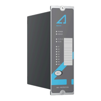
Figure. 4 - 1. Arc protection devices AQ-101 (left) and AQ-101D (right). The AQ-101 is designed according to the latest protection relay standards and is therefore suitable for installations in rough environments. These include utilities and power plants (both traditional and renewable), various heavy industry applications (off-shore, marine, oil, gas, mining, steel, etc.) as well... - Page 10 5 Device features AQ-101 is an arc flash protection device which can be applied to a variety of applications. It can be used on its own as a stand-alone device, or it can be a part of a more complex arc protection system by using binary inputs and outputs to connect multiple AQ 100 series devices together.
-
Page 11: Connections
6 Connections Instruction manual Version: 2.03 6 Connections The figures below depict the connections of AQ-101 and AQ-101D. Please note that the SF relay is in the de-energized position. Figure. 6 - 2. Rear terminals of AQ-101. © Arcteq Relays Ltd... -
Page 12: Simplified Block Diagram
Instruction manual Version: 2.03 Figure. 6 - 3. Connections of AQ-101D. 6.1 Simplified block diagram The figure below presents the main components that can be found in both the AQ-101 device and the AQ-101D variant. © Arcteq Relays Ltd IM00006... - Page 13 A A Q Q -101(D -101(D) ) 6 Connections Instruction manual Version: 2.03 Figure. 6.1 - 4. Simplified block diagram of AQ-101 and AQ-101D. © Arcteq Relays Ltd IM00006...
-
Page 14: Inputs
Figure. 6.2.1 - 5. Arc point sensor connections Both AQ-101 and AQ-101D have four (4) arc point sensor channels: S1, S2, S3 and S4. Up to three (3) arc point sensors can be connected to each channel. When the arc protection system has been set up, point sensor connections are constantly monitored. -
Page 15: Outputs
AQ 100 series device's binary outputs send out a short pulse every second. Binary inputs of the receiving AQ 100 series devices use these pulses to count the number of connected binary outputs. System self-supervision chapter for more information. NOTICE! TICE! Please note that the binary ouputs are polarity-sensitive. © Arcteq Relays Ltd IM00006... -
Page 16: Trip Relays
Whenever the device detects a system error or the auxiliary power supply is disconnected, the SF relay changes its state. The state stays this way until the device returns to a healthy condition. See the System self-supervision chapter for more information. © Arcteq Relays Ltd IM00006... -
Page 17: Auxiliary Voltage
Figure. 6.4 - 11. Auxiliary power supply connection The auxiliary power supply voltage is 92….265 V AC/DC. Alternatively, the optional auxiliary power supply can be of 18…72 V DC. This choice must be specified when ordering. © Arcteq Relays Ltd IM00006... -
Page 18: Arc Sensors C Sensors
Installing a connection cable is simple as each end of the sensor has a detachable cover over the cable connectors. Please remember to reattach the cover once the wires have been installed. NOTICE! TICE! The AQ-01 point sensor does no not t come with a connection cable! © Arcteq Relays Ltd IM00006... -
Page 19: Arc Light And Pressure Point Sensor Aq-02
AQ-07 is an arc light fiber optic loop sensor, which is a robust fiber optic cable with a practically unlimited bending radius. The sensor contains hundreds of glass fiber drains covered by a plastic tube, thus making it extremely strong and durable. Fiber sensors are distributed through the protected switchgear cells. © Arcteq Relays Ltd IM00006... -
Page 20: Arc Light Fiber Optic Loop Sensor Aq-08
If necessary, the ends of an AQ-07 cable can be ordered with heat shrinking tubing to avoid light detection outside the protected zone. The covered area can be one (1) or two (2) meters by default; if other lengths are required, please consult the Arcteq sales team. You can find the Contact and reference information page at the end of this manual. -
Page 21: Connecting Sensors
7.7.2 Fiber loop sensors 1. Drill holes on the wall for the sensor cable to enter the protected compartment. 2. Install protective covers in the holes to ensure the sensor cable remains unharmed by rough edges. © Arcteq Relays Ltd IM00006... - Page 22 4. Turn the black and blue receiver (“Rx”) and transceiver (“Tx”) screws counter-clockwise and plug in the sensor cable terminals. Then turn the screws clockwise to secure the terminals in their place. © Arcteq Relays Ltd IM00006...
-
Page 23: Operation And Config Tion And Configura Uration Tion
NOTICE! TICE! Please note that while the switch numbers and their functions are the same for both AQ-101 and AQ-101D, in the DIN rail variant of the device the switches are "upside down" (that is, switch 1 is at the top of the DIP switch when normally switch 8 is at the top)! Figure. -
Page 24: Available Logic Schemes
8.2 Available logic schemes The schemes described below are the most commonly used ones for AQ-101 devices. However, additional schemes are also available; please contact your nearest Arcteq representative for more information on those schemes. The schemes are configured using the DIP switches numbered 1…4 ("Scheme selection"). - Page 25 Instruction manual Version: 2.03 Figure. 8.2.1 - 16. Example connection for AQ-101 (SS:0) Figure. 8.2.1 - 17. The trip logic matrix for SS:0. 1. Activates only if channel has been set to light only mode or overcurrent signal (BI1) is ON.
-
Page 26: Ss:1 One Outgoing Feeder Per Device
AQ-110 incomer device. AQ-110 can send a master trip command to BI2 of the AQ-101 device. BI1 can be used for receiving external overcurrent signals. You can find a more detailed description of this scheme in the AQ-SAS booklet. -
Page 27: Ss:4 Two Outgoing Feeders Per Device
S4 or S5), BO1 sends the light signal to AQ-110 incomer device. AQ-110 can send a master trip command to BI2 of the AQ-101 device which will trip all trip relays (T1-T4). BI1 can be used for receiving external overcurrent signals. -
Page 28: Push Button (Set)
SET, and it can be used for all operational functions. The push button is used for: 1. Setting up the system (also known as auto-configuration) 2. Resetting the indicator LEDs 3. Resetting latched outputs 4. Checking the input connections © Arcteq Relays Ltd IM00006... -
Page 29: System Setup (Auto-Configuration)
(2) seconds. The LEDs of the corresponding sensors, binary input channels and the “Power” LED start blinking. The LEDs blink as many times as there are connected sensors and binary output channels from other devices. © Arcteq Relays Ltd IM00006... -
Page 30: Circuit Breaker Failure Protection
8.5 LED indicator functions Both the AQ-101 and its AQ-101D variant have twelve (12) indication LEDs on the device's front panel. Apart from the "Power" and "Error" LEDs, the user can write their own identifications for each of the remaining LEDs on the text insert located in the transparent pocket next to the LEDs. -
Page 31: Non-Volatile Memory
This feature is especially important if tripping causes the device to lose its auxiliary power. The non-volatile memory does not require a power supply to maintain the information and it retains the settings and the indications permanently without power. © Arcteq Relays Ltd IM00006... -
Page 32: Sy Y St Stem Self-Super 9 S Em Self-Supervision Vision
The device goes into Error mode, if a DIP switch setting is changed after the system setup procedure has been performed. However, the configured (stored) settings are still valid and the device is still operational. © Arcteq Relays Ltd IM00006... -
Page 33: Applica A Tion Examples
I> signal to the AQ-101 (or AQ-101D) device. Please note that the S1 sensor channel can be set to operate solely on the light condition, even if other channels are set to operate on both conditions. -
Page 34: Wind Power Application (Light Only)
Figure. 10.1 - 26. Connections of the I> and L> application for AQ-101. 10.2 Wind power application (light only) AQ-101 and AQ-101D can be applied by using arc light as the only tripping criterion. This example application describes a typical wind power scheme, where a permanent magnet synchronous generator is applied with a converter cabinet and an MV/LV transformer. - Page 35 Additionally, the application uses the electronic lock-out relay T3 to provide a safety loop: it ensures that the fault is recognized and corrected before the generator is put back into service. Figure. 10.2 - 27. The wind power application's wiring diagram for AQ-101. © Arcteq Relays Ltd IM00006...
- Page 36 A A Q Q -101(D -101(D) ) 11 Wiring example Instruction manual Version: 2.03 11 Wiring example Figure. 11 - 28. Example wiring diagram for AQ-101 and AQ-101D. © Arcteq Relays Ltd IM00006...
-
Page 37: Dimensions And Installa Imensions And Installation Tion
Instruction manual Version: 2.03 12 Dimensions and installation AQ-101 can be either door-mounted or panel-mounted in a standard 19 inch rack. The device's dimensions (without PCBs) are as follows: • Height: 157 mm (6.18 in) • Width: 50 mm (1.97 in) •... - Page 38 A A Q Q -101(D -101(D) ) 12 Dimensions and installation Instruction manual Version: 2.03 Figure. 12 - 29. Dimensions of the device and its cut-out panel. © Arcteq Relays Ltd IM00006...
- Page 39 Figure. 12 - 30. Dimensions of the DIN rail variant of the device. The following image illustrates how a device is installed into a cut-out. Please note that as AQ-101 is narrower than the device in the image, they are connected to the cut-out panel by a single screw on both the top and the bottom of the front panel instead of the two depicted below.
-
Page 40: Testing Esting
10. Verify that no trip has occured and only the indicator LED of the sensor activation is lit. 11. If you are using the BO1 signal and have configured it to send light information, verify that it is activated. 12. Press the SET SET push button to reset all indications and latches. © Arcteq Relays Ltd IM00006... -
Page 41: Testing The Cbfp Function
2. Connect one of the test set's outputs to a strong camera flash to initialize the flash and to configure the set's timer to start simultaneously with the flash. 3. Connect one of the AQ-101 device's trip outputs (T1, T2, T3, T4) to a test set input and configure the input to stop the timer. -
Page 42: Test Plan Example
A A Q Q -101(D -101(D) ) 13 Testing Instruction manual Version: 2.03 13.5 Test plan example © Arcteq Relays Ltd IM00006... -
Page 43: Tr R Oubleshoo 14 T Oubleshooting Ting
A A Q Q -101(D -101(D) ) 14 Troubleshooting Instruction manual Version: 2.03 14 Troubleshooting Table. 14 - 6. Troubleshooting guide for AQ-101 variants. P P r r oblem oblem P P ossible sol ossible solution( ution(s) s) Check the sensor's cable wiring. -
Page 44: Mounting And Installation
-101(D) ) 15 Technical data Instruction manual Version: 2.03 15 Technical data 15.1 Mounting and installation Table. 15.1 - 7. Technical data for relay mounting and installation (AQ-101 & AQ-101LV). Panel: - material metal - thickness (min...max) 1.0...5.0 mm (0.04...0.20 in) -
Page 45: Operating Times
4 NO or or 3 NO + 1 NC Voltage withstand 250 V AC/DC Carry: - continuous carry - make-and-carry for 3 s 16 A - make-and-carry for 0.5 s 30 A Breaking capacity DC* 40 W (0.36 A at 110 V DC) © Arcteq Relays Ltd IM00006... -
Page 46: Binary Output(S)
Light intensity threshold 25,000 lux 50,000 lux Detection radius 180º Mechanical protection IP 20 Sensor cable specification Shielded twisted pair 0.75 mm (AWG: 18) Maximum sensor cable length (per 200 m channel) Operating temperature –20…+85 ºC © Arcteq Relays Ltd IM00006... -
Page 47: Fiber Optic Loop Sensors
AQ-07 fiber optic loop sensor Table. 15.9 - 18. Technical data for the AQ-07 fiber optic loop sensor. Material Covered glass fiber Light intensity threshold 8,000 lux Cable length (min…max) 3…50 m Cable diameter 1.2 mm Detection radius 360º © Arcteq Relays Ltd IM00006... -
Page 48: Disturbance Tests
= 150 kHz…80 MHz, 10 V/m (EN 61000-4-6, level 3) 15.11 Voltage tests Table. 15.11 - 21. Technical data for the voltage tests. Insulation test voltage (IEC 60255-5) 2 kV, 50 Hz, 1 min © Arcteq Relays Ltd IM00006... -
Page 49: Mechanical Tests
Protection: - front IP 50 - back IP 20 50 × 157 × 160 mm Device dimensions (W × H × D) 145 × 109 × 34 mm (the DIN rail variant) Weight 0.7 kg © Arcteq Relays Ltd IM00006... -
Page 50: Ordering Inf Dering Informa Ormation Tion
A A Q Q -101(D -101(D) ) 16 Ordering information Instruction manual Version: 2.03 16 Ordering information AQ-101 point sensor device (panel mounted) AQ-101D point sensor device (DIN rail mounted) © Arcteq Relays Ltd IM00006... - Page 51 Accessories Order Description Note Manufacturer code Wall mounting AQX006 For AQ-103 and AQ-110x variants (MV and LV). Arcteq Ltd. bracket Wall mounting For AQ-101, AQ-101S and AQ-102 devices (MV and AQX016 Arcteq Ltd. bracket LV). © Arcteq Relays Ltd IM00006...
-
Page 52: Contact And R Ence Informa Ormation Tion
Arcteq Relays Ltd. Visiting and postal address Kvartsikatu 2 A 1 65300 Vaasa, Finland Contacts Phone: +358 10 3221 370 Website: arcteq.fi Technical support: support.arcteq.fi +358 10 3221 388 (EET 9:00 – 17.00) E-mail (sales): sales@arcteq.fi © Arcteq Relays Ltd IM00006...
Need help?
Do you have a question about the AQ-101 and is the answer not in the manual?
Questions and answers