Table of Contents
Advertisement
Advertisement
Table of Contents

Subscribe to Our Youtube Channel
Related Manuals for Beckhoff AM3100 Series


Summary of Contents for Beckhoff AM3100 Series
- Page 1 Documentation Synchronous Servomotor AM3100 Version: 1.4 Date: 2012-04-20...
-
Page 2: Documented Motors
Drive Technology Documented motors Documented motors Stand- Rated Rotor moment of inertia Weight Standstill still supply AM3100 Rated speed without with without with torque current voltage brake brake brake brake AM3111-030x 0,21 Nm 3,22 A 3000 min 24 V DC 0,026 Kgcm 0,034 Kgcm 0,40 Kg... -
Page 3: Table Of Contents
Drive Technology Table of contents – AM3100 Chapter Page Table of contents – AM3100 Documented motors.............................2 Table of contents – AM3100 ..........................3 Foreword ..............................5 Notes on the documentation ......................5 Disclaimer ............................5 Brands ............................5 Patents ............................5 Copyright............................5 Documentation issue status......................5 Appropriate use..........................6 Guidelines and Standards ........................7 EC declaration of conformity......................7 Safety ..............................8... - Page 4 Radial / axial forces at the shaft end....................29 10.5.2 Characteristic torque / speed curves ...................29 10.6 Characteristic torque / speed curves ...................30 Appendix .............................31 11.1 Support and Service........................31 11.1.1 Beckhoff Support..........................31 11.1.2 Beckhoff Service ..........................31 11.2 Beckhoff headquarters .........................31 Version: 1.4 AM3100...
-
Page 5: Foreword
Danger for persons, the environment or equipment The motors are operated in the drive system in conjunction with Beckhoff servo motor EtherCAT terminals. Please observe the entire documentation which consists of: CAUTION −... -
Page 6: Appropriate Use
WARNING drive system. The servomotors from the AM3100 series are exclusively designed for installation as components in electrical systems or machines and may only be operated as integrated components of the system or machine. The motors may only be operated under the ambient conditions defined in this documentation. -
Page 7: Guidelines And Standards
Guidelines and Standards Danger for persons, the environment or equipment Servomotors of the AM3100 series are not classified as products within the meaning of the EC Machinery Directive. Operation of the servomotors in machines or systems is only permitted CAUTION once the machine or system manufacturers has provided evidence of CE conformity of the complete machine or system. -
Page 8: Safety
Drive Technology 3 Safety Safety General safety instructions 3.1.1 Personnel qualification This description is only intended for trained specialists in control, automation and drive engineering who are familiar with the applicable national standards. 3.1.2 Description of safety symbols The following safety symbols and associated safety instructions are used in this document. These safety instructions must be read and followed. -
Page 9: Special Safety Instructions For Am3100
The servomotors of the AM3100 series are not designed for stand-alone operation and are always installed in a machine or system. After installation the additional documentation and safety instructions provided by the machine manufacturer must be read and followed. -
Page 10: Handling
In accordance with the WEEE 2002/96/EC Directives we take old devices and accessories back for prof- essional disposal, provided the transport costs are taken over by the sender. Please send the devices to: Beckhoff Automation GmbH Eiserstrasse 5 33415 Verl Germany Version: 1.4... -
Page 11: Product Identification
Drive Technology 5 Product identification Product identification Scope of supply Please check that the delivery includes the following items: • Motor from the AM3100 series • Motor package leaflet (short info) Nameplate Standstill current Servomotor type Serial number Date of manufacture BECKHOFF S.N. -
Page 12: Technical Description
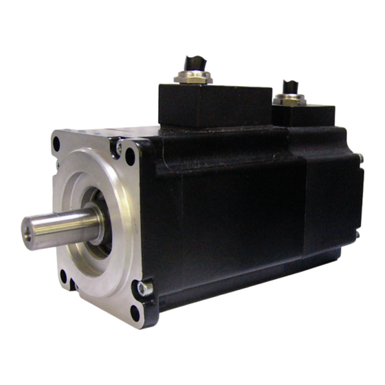
Technical description Design of the motors The synchronous servomotors of the AM3100 series are brushless three-phase motors for demanding servo- applications. In conjunction with our digital servo terminal they are particularly suitable for positioning tasks in industrial robots, machine tools, actuators etc. with demanding requirements in terms of dynamics and stability. -
Page 13: Standard Features
Drive Technology 6 Technical description Standard features 6.3.1 Style The basic style for the AM3100 synchronous servomotors is IM B5 according to DIN EN 60034-7. IM B 5 (B5) IM V 3 (V3) IM V 1 (V) 6.3.2 Shaft end, A-side Power transmission is made through the cylindrical shaft end A, fit h7 according to EN 50347. -
Page 14: Vibration Class
Drive Technology 6 Technical description 6.3.6 Vibration class The motors are made to vibration class A according to DIN EN 60034-14. For a speed range of 600-3600 rpm and a shaft centre height between 56-132 mm, this means that the actual value of the permitted vibration severity is 1.6 mm/s. -
Page 15: Options
Drive Technology 6 Technical description Options Holding brake The holding brake is integrated in the motor. It increases the motor length. Selection criteria The three-phase servomotors are designed for operation with servo terminals. Both units together form a speed or torque control loop. The main selection criteria are: —... -
Page 16: Mechanical Installation
Drive Technology 7 Mechanical installation Mechanical installation Important notes Destruction of the motors • Protect the motors from unacceptable stresses. Take care, especially during transport and handling, that components are not bent and that insulation clearances are not altered. Attention •... -
Page 17: Electrical Installation
Drive Technology 8 Electrical installation Electrical installation Important notes Serious risk of injury through electric shock! • Only staff qualified and trained in electrical engineering are allowed to wire up the motor. WARNING • Check the assignment of the servo terminal and the motor. Compare the rated voltage and the rated current of the devices. -
Page 18: Connection Of Motors With Pre-Assembled Cables
Beckhoff offers preassembled motor and feedback cables for safe, faster and flawless installation of the motors. Beckhoff cables have been tested with regard to the materials, shielding and connectors used. They ensure proper functioning and compliance with statutory regulations such as EMC, UL etc. The use of other cables may lead to unexpected interference and invalidate the warranty. - Page 19 Drive Technology 8 Electrical installation Flame resistance DIN EN 50265-2-1 Oil resistance UL 1581 Silicone-free CFC-free Halogen-free Sheath Material TMPU halogen free according to UL AWM & CSA AWM Shielding tinned copper braid Separator Polyester strap Colour Ral 2003 orange Power leads 4 x 0,75mm²...
- Page 20 Drive Technology 8 Electrical installation Max. vertical length Max. tensile load 20 N/mm² Operating temperature -20 to +60° C Standards and features UL AWM listed 80°C - 300V CSA AWM listed 80°C - 300V Flame resistance DIN EN 50265-2-1 Oil resistance UL 1581 Silicone-free CFC-free...
-
Page 21: El7201 Connection Diagram For Am3100 Motors With Resolver
Drive Technology 8 Electrical installation 8.2.2 EL7201 connection diagram for AM3100 motors with resolver Motor cable: ZK4704-0411-2xxx Resolver cable: ZK4724-0410-2xxx AM3100 Version: 1.4... -
Page 22: Screening Concept
Drive Technology 8 Electrical installation 8.2.3 Shielding concept Together with the shield busbar, the prefabricated cables from Beckhoff offer optimum protection against electromagnetic interference. Connection of the motor cable to the shield busbar Fasten the shield busbar supports (1) to the DIN rail (2). The DIN rail (2) must be in contact with the metallic rear wall of the control cabinet over a wide area. -
Page 23: Commissioning
Drive Technology 9 Commissioning Commissioning Important notes Serious risk of injury! • Only specialist personnel with extensive knowledge in the areas of electrical engineering / drive technology are allowed to install and commission the equipment. WARNING • The surface temperature of the motor can exceed 100 °C in operation. Check (measure) the temperature of the motor. - Page 24 Drive Technology 9 Commissioning Fault Possible cause Measures to remove the cause of the fault • Servo terminal not enabled • Supply ENABLE signal Motor doesn’t rotate • Break in setpoint lead • Check setpoint lead • Motor phases in wrong sequence •...
-
Page 25: Technical Data
Drive Technology 10 Technical data Technical data All data valid for 40 °C ambient temperature and 100 K overtemperature of the winding. The data can have a tolerance of +/- 10%. 10.1 Term definitions Standstill torque M [Nm] The standstill torque can be maintained indefinitely at a speed n<100 rpm and rated ambient conditions. Rated torque M [Nm] The rated torque is produced when the motor is drawing the rated current at the rated speed. -
Page 26: Electrical And Mechanical Data
Drive Technology 10 Technical data 10.2 Electrical and mechanical data Symbol Technical Data AM 3111 AM 3112 AM 3121 [Unit] Electrical data Standstill torque [Nm] 0,21 0,34 0,69 Standstill current 3,22 3,40 4,60 orms Max. mechanical speed [min 6000 6000 6000 Max. -
Page 27: Dimensional Drawing Am3111
Drive Technology 10 Technical data 10.3 Dimensional drawing AM3111 Resolver Motor type x - without brake x1 - with brake AM3111 10.3.1 Radial / axial forces at the shaft end 10.3.2 Characteristic torque / speed curves Characteristic torque / speed curves see section 10.5. AM3100 Version: 1.4... -
Page 28: Dimensional Drawing Am3112
Drive Technology 10 Technical data 10.4 Dimensional drawing AM3112 Resolver Motor type x - without brake x1 - with brake AM3112 10.4.1 Radial / axial forces at the shaft end 10.4.2 Characteristic torque / speed curves Characteristic torque / speed curves see section 10.5. Version: 1.4 AM3100... -
Page 29: Dimensional Drawing Am3121
Drive Technology 10 Technical data 10.5 Dimensional drawing AM3121 Resolver Motor type x - without brake x1 - with brake AM3121 10.5.1 Radial / axial forces at the shaft end 10.5.2 Characteristic torque / speed curves Characteristic torque / speed curves see section 10.5. AM3100 Version: 1.4... -
Page 30: Characteristic Torque / Speed Curves
Drive Technology 10 Technical data 10.6 Characteristic torque / speed curves AM3111 AM3112 AM3121 Version: 1.4 AM3100... -
Page 31: Appendix
33415 Verl Germany Phone: +49(0)5246/963-0 Fax: +49(0)5246/963-198 e-mail: info@beckhoff.com The addresses of the worldwide Beckhoff branch offices and representatives can be found on our website at www.beckhoff.com You will also find further documentation for Beckhoff components there. AM3100 Version: 1.4...
Need help?
Do you have a question about the AM3100 Series and is the answer not in the manual?
Questions and answers