Table of Contents
Advertisement
Quick Links
www.icpdas.com
Warranty
All products manufactured by ICP DAS are under warranty regarding
defective materials for a period of one year from the date of delivery to the
original purchaser.
Warning
ICP DAS assumes no liability for damages resulting from the use of this
product. ICP DAS reserves the right to change this manual at any time without
notice. The information furnished by ICP DAS is believed to be accurate and
reliable. However, no responsibility is assumed by ICP DAS for its use, or for any
infringements of patents or other rights of third parties resulting from its use.
Copyright
Copyright 2019 by ICP DAS. All rights are reserved.
Trademark
The names used for identification only may be registered trademarks of their
respective companies.
ALM-06-WF
ALM-06-WF User's Manual
User's Manual (Rev1.0, Feb./2019) ------------- 1
Advertisement
Table of Contents

Related Manuals for ICP DAS USA ALM-06-WF


Summary of Contents for ICP DAS USA ALM-06-WF
- Page 1 ALM-06-WF User’s Manual www.icpdas.com Warranty All products manufactured by ICP DAS are under warranty regarding defective materials for a period of one year from the date of delivery to the original purchaser. Warning ICP DAS assumes no liability for damages resulting from the use of this product.
- Page 2 ALM-06-WF User’s Manual Document Revision Version Date Description of changes Rev1.0 2019-05-17 First release for ALM-06-WF ALM-06-WF User’s Manual (Rev1.0, Feb./2019) ------------- 2...
-
Page 3: Table Of Contents
ALM-06-WF User’s Manual Table of Contents Introduction ..................5 1.1 Wireless connection mode ..............5 1.2 Features ....................5 1.2.1 Features Description ................ 6 Specifications ..................7 1.3 Hardware....................9 2.1 Outward Appearance ................9 2.1.1 ... - Page 4 ALM-06-WF User’s Manual 5.2.5 Data Encoding .................. 34 ALM-06-WF Address Mapping ............35 5.3 ALM-06-WF User’s Manual (Rev1.0, Feb./2019) ------------- 4...
-
Page 5: Introduction
1. Introduction The ALM-06-WF have WLAN connection complies with the IEEE802.11b/g/n standards. With the popularity of 802.11 network infrastructure, the ALM-06-WF make an easy way to incorporate wireless connectivity into monitoring and configuration. They also support Modbus TCP protocol and the network encryption configuration, which makes perfect integration to SCADA software and offer easy and safe access for users from anytime and anywhere. -
Page 6: Features Description
WEP and WPA are common types of security that are used to protect wireless networks. When WEP or WPA is turned on, ALM-06-WF uses a special security key combination to allow only devices that know this key to connect to its wireless network. -
Page 7: Specifications
ALM-06-WF User’s Manual Specifications Table 1-1: System Specifications Wi-Fi Interface Antenna Chip Antenna Output Power 18.0 dBm @ 1 DSSS / 14.5 dBm @ 54 OFDM Receive Sensitivity –95.7 dBm @ 1 DSSS /–74.0 dBm @ 54 OFDM Interface Wi-Fi 2.4G Standard Supported IEEE 802.11b/g/n... - Page 8 ALM-06-WF User’s Manual Table 1-2: I/O Specification Digital Input Channels Input Type Dry Contact: Sink Off Voltage Level: Open Dry Contact Level On Voltage Level: Close to GND Photo-Isolation 3750 VDC Input Condition Pulse Width must > 150mSec or more...
-
Page 9: Hardware
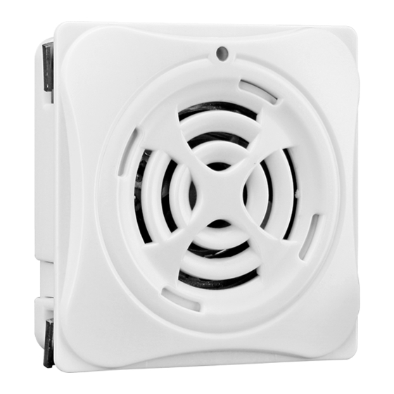
ALM-06-WF User’s Manual 2. Hardware 2.1 Outward Appearance ALM-06-WF contains I/O connectors, Micro SD, Reset to Default and LEDs. Power/Status LED Figure 2-1: Front Panel Connector Reset to Default Switch Micro SD(T-Flash) Figure 2-2: Back Panel ALM-06-WF User’s Manual (Rev1.0, Feb./2019) ------------- 9... -
Page 10: Led Indicator
Alarm Status Red LED 2.1.2 Connector Pin Define Terminal NO Pin Name Wire Color Brown Orange Yellow Green Blue DI.GND Gray Black Black Line Out Purple White White Figure 2-3: I/O Connector of ALM-06-WF ALM-06-WF User’s Manual (Rev1.0, Feb./2019) ------------- 10... -
Page 11: Reset To Default
AP mode. Figure 2-4: Reset button locate in the bottom side of ALM-06-WF Dimensions The diagrams below provide the dimensions of the ALM-06-WF to use in defining your enclosure specifications. All dimensions are in millimeters. Figure 2-5: Dimension of the ALM-06-WF ALM-06-WF User’s Manual (Rev1.0, Feb./2019) ------------- 11... -
Page 12: Wire Connection
ALM-06-WF User’s Manual Wire Connection 2.4.1 Wire connection define The following describe the wire color & function Figure 2-6: Wire color & function 2.4.2 I/O connection 2.4.2.1 Digital Input (DI) wiring Figure 2-7: DI Dry contact wiring ALM-06-WF User’s Manual (Rev1.0, Feb./2019) ------------- 12... - Page 13 ALM-06-WF User’s Manual 2.4.2.2 Relay Output wiring Figure 2-8: Relay Output wiring 2.4.2.3 Line Out wiring Figure 2-9: Line Out wiring 2.4.2.4 Power Input Figure 2-10: Power Input ALM-06-WF User’s Manual (Rev1.0, Feb./2019) ------------- 13...
-
Page 14: Software
The following is the main screens provided by ALM Utility, these utility tools can be thought as a useful tool for configuration and monitoring on the ALM-06-WF. It supplies several functions, such as Monitoring, Configuration, Connection, Wi-Fi setting and F/W upgrade, etc..,... -
Page 15: Controller Status
ALM-06-WF User’s Manual 3.1.2 Controller Status Show the connected controller information, user define Locate string, RSSI strength, Device IP & Static IP button for changing device IP in STA mode. 3.1.3 DI/DO Status & Control Show the DI/Relay Output status, The value can be read(DI) or set(Relay Output) in this area. -
Page 16: Icon Button
ALM-06-WF User’s Manual 3.1.5 Icon Button ICON function Open the Setup Screen (Android versions Setup Setup function under the icon) Red Led blinking, use to find the connected Find Controller Controller Refresh status Refresh Only Android Device, Menu Include setup, FW Version & About. -
Page 17: Configuration/Setup
ALM-06-WF User’s Manual 3.1.6 Configuration/Setup Figure 3-2: ALM Utility setup page Click apply icon to save each subject’s setting, after finish all setting click to make device take effect on new setting AP: SSID Name 1. Default Controller’s SSID in Wi-Fi AP mode, will be ALM-06-xxxxxx. - Page 18 ALM-06-WF User’s Manual Static IP: IP: Specific an IP that is not been used. Mask: Default will be 255.255.255.0. Gateway: Basically define in the AP you are going to connect. Service Set Identifier: Connected devices must be the same SSID, SSID SSID length must not exceed 31 characters.
-
Page 19: Station Mode (Sta) Ip Scanner
ALM-06-WF User’s Manual 3.2 Station Mode (STA) IP scanner There are lot of free IP scanner tools in both Windows & Android OS, for example “Advanced IP Scanner” for Windows, “Network Analyzer” for Android, those are high performance scanner tools on each OS. -
Page 20: Alarm Mode & Audio Editor
3.3 Alarm Mode & Audio Editor ALM-06-WF contain 8 kinds of alarm mode, Mode 0 ~ 3 are DI1~DI6 in single independence channel trigger, in DIx channel priority, the priority of DI channel is DI6 > DI5... > DI1. -
Page 21: Start Your Edit
Read Device button, in Device Edit mode audio file cannot be read back, can only be modify or recover. Write Device button will download all your setting & audio files into ALM-06-WF device through Wi-Fi. Also you can copy all the file inside your project directory to the Micro SD Card. - Page 22 File No. play back, select Play Source (Audio file original location) or Play Project (Audio file in project) or Play Device (Audio file in ALM-06-WF device’s SD Card, only when Device Edit selected), click File No. and press Play button to play, and Stop button to break playback.
- Page 23 ALM-06-WF User’s Manual (3) Alarm Config: Frist you need to select Alarm Mode, then you can assign audio File No. for each alarm channel from combo box, playback Repeat count & Alarm Output Relay. To simulation the alarm channel audio playback, select the channel from combo box, press Channel test button to play, and Stop to break the playback, show as below.
-
Page 24: Make A Micro Sd From Project
ALM-06-WF User’s Manual Make a Micro SD from project 3.4.1 Copy all the file to the MicroSD root directory where your project directory locate, this will be the same as Write Device from project. Insert a New MicroSD 3.4.2 To start a new MicroSD, please insert to a PC before use it, this will make Microsoft OS fill the correct capacity into the MicroSD. -
Page 25: Alarm Mode Description
When alarm in playback process, any input trigger will ignore. The highest DIx channel priority input will take place after the previous playback complete. Figure 3-8: ALM-06-WF Mode 0 Mode 1: Channel Trigger-Trigger Input priority Playback DI1 to DI6 playback in single independence trigger of 6 channels. - Page 26 Playback will repeat when input are not release & will stop immediately when input released. When multi trigger in same time the highest DIx channel priority will take place Figure 3-6: ALM-06-WF Mode 2 Mode 3: Channel Trigger- Memory Once Playback ...
- Page 27 When alarm in playback process, any input trigger will ignore. The highest binary channel priority input will take place after the previous playback complete, DI6 is the most highest channel. Figure 3-8: ALM-06-WF Mode 4 Mode 5: Binary Trigger-Trigger Input priority Playback ...
- Page 28 Playback will repeat when input are not release & will stop immediately when input released. When multi trigger in same time the highest binary channel priority will take place, DI6 is the most highest channel. Figure 3-10: ALM-06-WF Mode 6 Mode 7: Binary Trigger- Memory Once Playback ...
-
Page 29: Application
ALM-06-WF User’s Manual 4. Application Users can use a Computer or Smart Device to communicate with the ALM devices in the application. It can complete the purpose of control to wireless network by this way. Figure 4-1: ALM + PC/Laptop/Smart Device application architecture 4.1 Connection with Modbus TCP utility... - Page 30 ALM-06-WF User’s Manual e. Use the function code "0x01", and set the Reference Number as "0x00", Bit Count as "0x01" to get the Relay Output value. Figure 4-3: Relay Status reading screen g. Use the function code "0x05", and set the Reference Number as "0x00", value as "0xFF"...
-
Page 31: Modbus Applications
ALM-06-WF User’s Manual 5. Modbus Applications The ALM-06-WF include a Modbus port that allows you to access terminals data via Wi-Fi and communicates using a master-slave technique in which only one device (the master) can initiate transactions (called queries). The other devices (slaves) respond by supplying the requested data to the master, or by taking the action requested in the query. -
Page 32: Protocol Description
ALM-06-WF User’s Manual 5.2 Protocol Description The Modbus protocol defines a simple protocol data unit independent of the underlying communication layers. The mapping of Modbus protocol on network can introduce some additional fields on the application data unit. Modbus/TCP Application Data Unit... -
Page 33: Function Code
ALM-06-WF User’s Manual 5.2.2 Function Code The function code field of a Modbus data unit is coded in one byte. Valid codes are in the range of 1 ... 255 decimal (the range 128 - 255 is reserved and used or exception responses). -
Page 34: Response
ALM-06-WF User’s Manual 5.2.4 Response If no error occurs related to the Modbus function requested in a properly received Modbus PDU (Protocol Data Unit) the data field of a Modbus response from a server to a client contains the data requested. If an error related to the Modbus function requested occurs, the field contains an exception code that the server application can use to determine the next action to be taken. - Page 35 32-bits items at a time; therefore, each of these data items will fit within 2 register that is read. Value Word Word 0x12345678 0x5678 0x1234 Table 5-5: A 32-bits double word item 5.3 ALM-06-WF Address Mapping Address Descriptions Range Access Type 00001 Digital Output 0=OFF, 1=ON 00002...
- Page 36 40001 Volume Level (0~10) 16bit Word Table 5-10: FC16 Write multiple AO address (4xxxx) Technical Support If you have problems about using the ALM-06-WF controller, please contact ICP DAS Product Support. Email: service@icpdas.com ALM-06-WF User’s Manual (Rev1.0, Feb./2019) ------------- 36...
Need help?
Do you have a question about the ALM-06-WF and is the answer not in the manual?
Questions and answers