Sign In
Upload
Manuals
Brands
GREE Manuals
Inverter
GMV5 Series
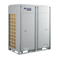
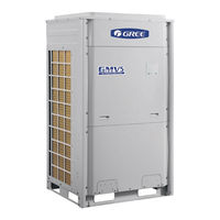
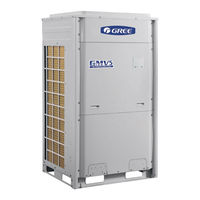
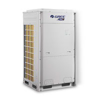
GREE GMV5 Series Manuals
Manuals and User Guides for GREE GMV5 Series. We have
12
GREE GMV5 Series manuals available for free PDF download: Service Manual, Manual, Owner's Manual, Technical & Service Manual
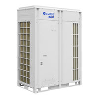
Gree GMV5 Series Service Manual (392 pages)
DC INVERTER MULTI VRF UNITS T1/R410A/50-60Hz
Brand:
Gree
| Category:
Inverter
| Size: 26 MB
Table of Contents
Table of Contents
2
Safety Precautions
6
Product List
7
Outdoor Unit
7
Hot Water Generator
7
Chapter 1: Product Introduction
7
Basic Parameter of Unit
8
Water Tank
8
Performance Parameter of Outdoor Unit
8
Performance Parameter of Hot Water Generator
9
Performance Parameter of Water Tank
10
Product Functions
11
Outline of Features
11
Description of Features
11
Basic Operational Principle
12
Flow Diagram of System
12
Instruction of Flow
12
Naming Rules of Outdoor Unit
13
Naming Rules of Indoor Unit
13
Naming Rules of Hot Water Generator
14
Naming Rules of Water Tank
14
Product Model Selection and Collocation
15
Usage Mode 1: Air Conditioner + Hot Water
15
Installation Methods
15
Usage Mode 2: Air Conditioner + Hot Water + Floor Heating
16
Usage Mode 3: Air Conditioner + Floor Heating
17
Revision of Product Capacity
20
Requirement for Connecting Quantity
20
Notices for Model Selection
20
Product Operating Range
20
Capacity Code
20
Capacity Revision Method for Indoor and Outdoor Units
20
Revision of Ambient Temperature and Collocation Rate Capacity
21
Revision of Cooling Capacity
21
Revision of Heating Capacity
28
Revision Coefficient of Heating Water Capacity
35
Revision of Floor Heating Capacity
37
Revision of Length and Fall Difference of Connecting Pipe
39
Heating Frosting Revision Factor
40
Model Selection and Installation
40
Notices for Model Selection
40
Overall Model Selection Steps
42
Usage
42
Air Conditioner+Heating Water+Floor Heating
42
Air Conditioner+Heating Water/Floor
42
Basic Conditions
43
Define Using Demand of User
43
Define Collication Method of Unit
43
Model Selection Example 1: Air Conditioner + Heating Water + Floor Heating, Air Conditioner + Floor Heating
43
Initial Selection of Outdoor Unit
44
Capacity Revision of Outdoor Unit
44
Model Selection of Generator
45
Checkup of Actual Output Capacity of each Indoor Unit
45
Calculation of Floor Heating Load
45
Model Selection of Water Tank
46
Initial Selection of Generator
46
Checkup of Quantity and Capacity of Generator
46
Calculation of Water Consumption
47
Calculation for Water Storage Capacity of Water Tank
47
Design of Floor Heating Engineering
48
Define Model of Water Tank
48
Final Conclusion for Model Selection of Whole Unit
49
Model Selection of Air Conditioner
50
Model Selection Example 2: Air Conditioner + Heating Water
50
Unit Control
51
General Control Method
51
Schematic Diagram of Unit Control
51
Chapter 2: Control
51
Capacity DIP Switch
52
Fan Emergency Operation DIP Switch
52
Explanation on Schematic Diagram
53
Master Unit Setting DIP Switch
53
Master Control System
53
Input and Output Control Quantity
53
Drive Control System
54
Hydro Box Control System
55
Operation Flowchart of Indoor Air Conditioner
56
Cooling Operation
57
Drying Operation
58
Heating Operation
59
Water Heating Operation
60
Cooling and Water Heating Operation
61
Heating and Water Heating Operation
62
Operation Flow of Outdoor Unit
63
Air Supply Operation
63
Remote Controller
69
Indoor Unit Wired Controller
70
Display
70
LCD of Wired Controller
70
LCD Display Instructions
70
Graphics of Buttons
72
Function Instructions of Buttons
72
Installation and Debugging of Wired Controller
72
Dimension of Wired Controller
72
Installation of Wired Controller
73
Selection of Communication Wire
73
Parts of Wired Controller
73
Length of Communication Wire
73
Installation Requirements
74
Wiring Requirements
74
One/Two Wired Controller Control One Indoor Unit
74
Wiring Instructions
75
One/Two Wired Controller Controls Multiple Indoor Units
75
Installation
76
Debugging
77
Set Master Indoor Unit
77
User Parameter Query
77
Disassembly
77
User Parameter Settings
79
List of User Parameter Settings
80
Engineering Parameter Query
82
List of Engineering Parameter Query
82
Engineering Parameter Settings
87
List of Engineering Parameter Settings
88
Hydro Box Wired Controller
92
Display
92
Buttons
94
Installation and Debugging of Wired Controller
95
Parameter Query
99
Parameter Settings
101
Operation Instructions
102
Switch between Water Heating Interface and Floor Heating Interface
102
On/Off of Water Heating
103
Mode Setting of Water Heating
103
Water Temperature Setting of Water Heating
103
Switch of Water Heating Functions
104
Setting of Sunflower Function
104
Setting of Water Heating Water Temperature Auto Setting
105
Setting of High-Temperature Sterilizing
105
Setting of Rapid Water Heating
107
Setting of Water Heating Timer On/Off
107
Setting of Preset Water Heating
110
On/Off of Floor Heating
113
Water Temperature Setting of Floor Heating
113
Switch of Floor Heating Functions
113
Setting of Floor Heating Water Temperature Auto Setting
114
Setting of Rapid Floor Heating
114
Setting of Floor Heating Absence Function
114
Setting of Floor Heating Timer On/Off
114
Setting of Clock
116
Malfunction Display
117
Setting of Cleaning
117
Remote Shield
117
Child Lock
117
Table of Malfunction Codes for Outdoor Unit
118
Table of Malfunction Codes for Hydro Box
122
Table of Commissioning Codes
122
Table of Status Codes
123
Engineering Installation Flowchart
124
Chapter 3 Installation
124
Common Tools and Devices
125
Preparation before Installation
127
Notices for Installation Engineering
127
Safety Requirements for Installation Engineering
127
Importance of Installation Engineering
127
Cooperation between Different Professions
128
Onsite Review of Design Drawing
129
Requirements for Cooperation with Civil Engineering
129
Requirements for Cooperation with Decoration Engineering
129
Requirements for Cooperation with Electric
129
Selection of Installation Materials
130
Requirements for Selecting Installation Materials
131
Copper Pipe
131
Condensate Water Pipe
131
Insulation Material
131
Water System Pipe
132
Floor Heating Pipe
132
Communication Cable
132
Communication Cable Selection for ODU and Idus
132
Three Operation Modes
133
Power Cable
133
Operation Mode 1: Air Conditioning + Water Heating
133
Operation Mode 2: Air Conditioning + Water Heating + Floor Heating
134
Operation Mode 3: Air Conditioning + Floor Heating
135
ODU Dimensions and Installation Hole Size
138
Selection of Outdoor Unit Installation Place
138
Installation Space Requirement for ODU
138
Monsoons Must be Considered During ODU Installation
140
Snow Must be Considered During ODU Installation
140
Installation Space Requirement for Equipment Floor
140
Preparation before Installing Static Pressure Ventilating Duct
140
Installation of Pressure Ventilating Duct
141
Installation Foundation of ODU
143
Installation of IDU
144
Vibration Reduction for ODU
144
Outline Dimension and Installation Hole Dimension of Hydro Box
145
Installation Position of Hydro Box
145
Requirements for Installation Space of Hydro Box (Unit: MM)
145
Installation Procedures of Hydro Box
147
Internal Structure and Pipeline Instruction of Hydro Box
148
Installation of Water Tank
149
Outline Dimension and Installation Dimension of Water Tank
149
Installation Position of Water Tank
150
Installation Notice for Water Tank
150
Design, Installation and Insulation of Refrigerant Pipeline
151
Notices for Pipeline Design
151
Schematic Diagram of Refrigerant Piping
152
Piping Instruction
152
Schematic Diagram for Refrigerant Piping of Top Discharge Outdoor Unit
153
Allowable Length and Height Different of Refrigerant Piping of IDU and ODU
154
Size of Refrigerant Piping
155
Installation and Insulation of Refrigerant Pipe
158
Pipe Installation for Cooling System
158
Processing to Refrigerant Pipes
158
Cut-Off and Burring
158
Installation of Refrigerant Pipes
159
Operation Sequence
159
Construction of Support, Hanger, and Bracket
159
Shaping and Fixing of Pipes
159
Pipe Connection
160
Welding Protection
160
Requirements on Manifold Installation
161
Pipe Cleaning by Nitrogen
162
Air-Tightness Test
164
Vacuumization and Desiccation for the System
164
Importance of the Air-Tightness Test
164
Procedure for Performing the Air-Tightness Test
164
Insulation for the Refrigerant System Pipe
165
Insulation Materials
165
Thickness of the Insulation Layer
165
Procedure of Insulation
165
Pipe Installation and Insulation for the Condensate Water System and Insulation for the Ducts
166
Installation of Drain Pipes for Different Types of Idus
168
Drain Pipe Installation for Hidden Duct Type IDU
168
Drain Test
169
Full Water Test
169
Drain Pipe Installation for Cassette Type IDU
169
Installation and Insulation of Hot Water System Pipeline
170
Insulation for Air Ducts
170
Connection of Hot Water System Pipeline
170
Insulation for the Condensate Water Pipe
170
Connection Schematic Diagram for Hydro Box and Water Tank
171
Connection Schematic Diagram for Hydro Box and Floor Heating
172
Schematic of Solar Water Heater Connected with System for Heating
172
Connection Schematic of Hydro Box with Water Tank and Floor Heating
172
Connection Requirements of Hydro Box and Water Tank
174
Installation Requirements of Water System
174
Capacity Setting of Water Tank
174
Installation of Floor Heating Performer (Floor Heating Water Separation Valve)
177
Electric Installation
180
Precautions
180
Installation of Power
182
Procedure for Installing the Power Cable
182
Power Cable Diameter and Circuit Breaker Selection
182
Odu
182
Hydro Box
183
Idu
183
External Wiring Diagram of Unit
185
ODU with Hydro Box and IDU
185
Hydro Box and Water Tank
185
Wiring Diagram of ODU
187
Wiring Diagram of Hydro Box
187
Installation of the Communication System
188
Connection of Communication Cable
188
Communication Way
188
Selection of the Material of Communication Cable
188
Communication Cable Selection for Idus/Hydro Box and Wired Controller
189
Communication Cable Selection for ODU and Idus/Hydro Box
189
Setting of Communication Address
190
Connection of Communication Cables
190
Connection Way and Procedures of Communication Cable
191
Connection of Communication Cable between ODU and Idus/Hydro Box
191
Communication Connection between the IDU and Wired Controller
192
One/Two Wired Controller Controlling One IDU
192
One/Two Wired Controller Controlling Multiple Idus
193
Communication Connection between the Hydro Box and Wired Controller
194
Connection between the Duct Type IDU and Receiver Board
196
Refrigerant Charging
197
Advertisement
GREE GMV5 Series Service Manual (402 pages)
HR DC INVERTER VRF UNITS
Brand:
GREE
| Category:
Inverter
| Size: 36 MB
Table of Contents
Table of Contents
2
Preface
4
Basic Operating Principle
5
Models List
5
Chapter 1 Introduction to Basic Features of Units
5
Internal Piping Design of the Units
6
Piping Diagram of GMV-Q224WM/E-X and GMV-Q280WM/E-X
6
Piping Diagram of GMV-Q335WM/E-X
7
Piping Diagram of GMV-Q400WM/E-X and GMV-Q450WM/E-X
8
Names and Main Functions of Components
8
Basic Parameters of Unit
10
Basic Parameters of ODU
10
Basic Parameters for Mode Exchanger
16
Connection Sketch Map of System
16
One-To-One Mode Exchanger NCHS1C
16
One-To-Two Mode Exchanger NCHS2C
17
One-To-Four Mode Exchanger NCHS4C
17
One-To-Eight Mode Exchanger NCHS8C
17
Electrical Parameters
19
Power Cable Wire Gauge and Circuit Breaker Selection
19
Circuit Diagram
21
Circuit Diagram of GMV-Q224WM/E-X and GMV-Q280WM/E-X
21
Circuit Diagram of GMV-Q335WM/E-X
21
Circuit Diagram of GMV-Q400WM/E-X and GMV-Q450WM/E-X
22
Basic Requirement for Pipe Connection
23
Precautions on Refrigerant Leakage
25
Unit Operating Temperature
26
Installation Safety
26
Chapter 2 Installation
26
Part 1 Engineering Installation Preparation
26
Cooperation between Different Professions
28
Requirements for Cooperation with Civil Engineering
28
Requirements for Cooperation with Decoration Engineering
28
Onsite Review of Design Drawing
30
Construction Organization Process
31
Requirement for Selecting Construction Materials
32
Requirement for Selecting Major Materials
32
Copper Pipe
32
Part 2 Material Selection
32
Insulation Material
33
Communication Cable and Control Cable
33
Power Cable
34
Selection of Communication Wire between Indoor Unit/Wired Controller
34
Connection between Indoor Units and Wired Controllers
34
Place Selection for Installing ODU
35
ODU Dimensions and Installation Hole Size
35
Part 3 Installation Space Requirement
35
Installation Space Requirement for ODU
36
Installation Space Requirements for Triple-Module Unit
37
Installation Space Requirement for Quad-Module Unit
37
Installation Space Requirement for Multiple Odus
38
Monsoons Must be Considered During ODU Installation
38
Installation Space Requirement for Mode Exchangers
43
Dimension of Outdoor Unit and Mounting Hole Position
43
NCHS1C Outline and Installation Dimension
43
NCHS2C Outline and Installation Dimension
43
NCHS8C Outline and Installation Dimension
44
Hole-Drilling for Bolt and Bolt Installation
46
Install the Mode Exchanger Temporarily
47
Check the Level of the Unit
47
Installation Site
48
Pipe Connection
49
Installation Instruction for Silencer
49
ODU Fixing
52
Vibration Reduction for ODU
52
Part 4 Requirements on Foundation Installation
52
Schematic Diagram of Piping Connection
54
Schematic Diagram of Piping Sequence
54
Part 5 Piping Connection
54
Allowable Pipe Length and Drop Height Among Indoor and Outdoor Units
55
Connection Pipe Among Outdoor Modules
57
Connection Sketch Map of Single-Module System
59
Connection Sketch Map of Multi-Module System
59
Size Requirement for Branch Pipe and Piping (Main Pipe)
59
Connecting Method for Indoor Unit with
64
Branch Selection of Indoor Unit of Mode Exchanger
64
Piping Size between Mode Exchanger and Downstream Indoor Unit
64
Precautions on Pipe Direction Design
65
Processing to Refrigerant Pipes
65
Cut-Off and Burring
65
Part 6 Pipe Installation and Insulation
65
Pipe Installation for the Cooling System
65
Pipe Cleaning
66
Pipe Bending
66
Pipe Expanding
66
Flaring
66
Installation of Refrigerant Pipes
67
Operation Sequence
67
Construction of Built-In Metal Fittings
67
Shaping and Fixing of Pipes
67
Flaring Connection
68
Socket Welding
68
Bell Socket Welding
68
Welding Protection
69
Requirements on Manifold Installation
69
Flange Connection
69
Pipe Cleaning by Nitrogen
70
Filter and Drier Installation for the ODU
71
Precautions
73
Installation of the Power Cable
73
Part 7 Electric and Controller Installation
73
Requirements on Power Cable Configuration
74
Installation of the Communication System
77
Connection of Communication Cable Terminals
78
Connection of Communication Cables
78
Connection Methods and Procedure of Communication System
81
Connection of Communication between Indoor and Outdoor Units
81
Connection of Communication between Indoor Unit and Wired Controller
84
One Wired Controller Controlling Multiple Idus
84
Two Wired Controllers Controlling Multiple Idus
85
Connection between the Air Duct Type IDU and Receiver Board
86
Communication Connection for Units with Central Control
87
Air - Tightness Test
88
Part 8: Vacuumization and Desiccation for the Refrigerant System
88
Vacuumization and Desiccation for the System
89
Calculation Method for Perfusing Refrigerant
91
Part 9: Refrigerant Perfusion
91
Method for Perfusing Refrigerant
93
Refrigerant Perfusion During Running
94
Precautions for Construction
95
Function Settings of Odus
95
Chapter 3 Commissioning Operation
95
Part 1 Security Requirements
95
Precautions for the Use of Refrigerants
95
Part 2 Introduction to Unit Functions
95
Unit Capacity DIP Switch
96
Centralized Control Address DIP Switch
96
Fan Emergency Operation DIP Switch
98
Outdoor Fan Static Pressure Setting DIP Switch
99
Reserved Function DIP Switch
99
Master Unit Setting DIP Switch
99
DIP Switch Example
100
System Function Button Operations
101
Introduction to Function Buttons
101
List of Functions
102
Description of Functions
102
A2 Refrigerant Recovery Operation
102
A6 Unit Cooling/Heating Function
103
A7 Outdoor Silent Mode
103
A8 Aftersales Vacuuming Mode
104
N0 Conservation Control
104
Forcible Defrosting Operation
104
Indoor Unit Project Number Offset
104
Function Setting Operations
105
Basic Operations
115
Restoring Factory Settings
116
Necessity of VRF Engineering Commissioning
117
Required Files and Tools for Engineering Commissioning
117
Required Tools for Engineering Commissioning of GREE VRF
117
Part 3 Commissioning Process
117
Engineering Commissioning Procedures
117
Pre-Commissioning Preparations
118
Overall Commissioning Plan
118
Composition of Commissioning Members
118
Pre-Commissioning Check
118
Electrical System Check
119
Check the Input Power
119
Communication System Check
120
Spot Check
121
References for Proper Unit Operation Parameters
140
Chapter 4 Maintenance
142
Part 1 Failure Code Table
142
How to Locate a Faulty IDU Promptly
147
Part 2 Exception and Troubleshooting
147
Exception Analyzing and Troubleshooting
148
Form Analyzing
148
System Faults
156
System Exhaust Temperature Exception
156
Pressure Exception
160
Poor Cooling/Heating Performance
165
“A0” Unit Debug Status
168
“A2” Refrigerant Recovery Operation Status
168
“A3” Defrosting Status
168
“A4” Oil Return Status
168
“A6” Cooling and Heating Function Setting Status
169
“A7” Quiet Mode Setting Status
169
“A8” Vacuum Mode
169
“AH” Heating Status
169
“AC” Cooling Status
170
“AF” Supply Air Status
170
“AE” Manual Refrigerant Charging Status
170
“AJ” Filter Dirty Alarm
170
“AU” Long-Distance Control Emergency Stop Status
171
“Ab” Emergency Stop Operation Status
171
“Ad” Limited Operation Status
171
“B1” Outdoor Ambient Temperature Sensor Error
171
“B2” Defrost Temperature Sensor 1 Error
172
“B3” Defrost Temperature Sensor 2 Error
173
“B4” Malfunction of Liquid Temperature Sensor of Sub-Cooler
174
“B5” Malfunction of Gas Temperature Sensor of Sub-Cooler
175
“C0” IDU and ODU, IDU Wired Controller Communication Error
181
“C3” Main Control and Inverter Fan Drive Communication Error
183
“C4” IDU Missing Error
185
“C5” IDU Project Code Conflict
185
“C6” Outdoor Unit Quantity Inconsistency Warning
186
“C8” Compressor Emergency Operation Status
186
“C9” Emergency Operation Status of Fan
187
“CA” Emergency Operation Status of Module
187
“CH” Rated Capacity Ratio Is too High
187
“CL” Rated Capacity Ratio Is too Low
187
“CC” no Master Controlling Unit Error
188
“CF” Multiple Master Controlling Units Error
188
“CJ” System Address Code Conflict
189
Detecting Circuit Is Abnormal
189
“CP” Multiple Master Wired Controller Error
190
“Cb” IP Address Allocation Overflow
190
“D1” Indoor Circuit Board Error
191
“D3” Ambient Temperature Sensor Error
191
“D4” Inlet Pipe Temperature Sensor Error
192
“D6” Outlet Pipe Temperature Sensor Error
193
“D7” Humidity Sensor Error
193
“D9” Jumper Cap Error
194
“Da” IDU Network Address Error
195
“Dh” Wired Controller Circuit Board Error
195
“DC” Capacity DIP Switch Setting Error
196
“Dl” Air Outlet Temperature Sensor Error
196
“Db” Project Debugging
197
“E1” High Pressure Protection
197
“E3” System Low Pressure Protection
201
“E4” Compressor High Discharge Temperature Protection
203
“F0” ODU Mainboard Error
205
“F1” High Pressure Sensor Error
205
“F3” Low Pressure Sensor Error
206
“F5” Compressor 1 Discharge Temperature Sensor Error
207
“F6” Compressor 2 Discharge Temperature Sensor Error
208
“F7” Compressor 3 Discharge Temperature Sensor Error
209
“F8” Compressor 4 Discharge Temperature Sensor Error
210
“F9” Compressor 5 Discharge Temperature Sensor Error
211
“FA” Compressor 6 Discharge Temperature Sensor Error
212
“FH” Compressor 1 Current Sensor Error
213
“FC” Compressor 2 Current Sensor Error
214
“FL” Compressor 3 Current Sensor Error
215
“FE” Compressor 4 Current Sensor Error
217
“FF” Compressor 5 Current Sensor Error
217
“FJ” Compressor 6 Current Sensor Error
218
“FU” Compressor 1 Shell Top Temperature Sensor Error
220
“Fb” Compressor 2 Shell Top Temperature Sensor Error
220
“H0” Fan Drive Board Error
221
“H1” Fan Drive Board Operation Error
222
“H2” Fan Drive Board Power Supply Voltage Protection
222
“H3” Fan Drive Module Reset Protection
222
“H5” Inverter Fan Overcurrent Protection
223
“H6” Drive IPM Module Protection of Fan
224
“H7” Fan Drive Temperature Sensor Error
225
“H8” Fan Drive IPM High Temperature Protection
226
“H9” Desynchronizing Protection of Inverter Compressor
227
“HC” AC Input Voltage of Drive of Inverter Fan
228
Gree GMV5 Series Service Manual (424 pages)
DC Inverter VRF Units For North America T1/R410A/60Hz
Brand:
Gree
| Category:
Inverter
| Size: 26 MB
Table of Contents
Table of Contents
2
Preface
4
Safty Precautions
5
Chapter 1 Introduction to Basic Features of Units
10
Models List
10
Basic Operating Principle
10
Internal Piping Design of the Units
11
Piping Diagram of GMV-72WM/B-F(U) and GMV-96WM/B-F(U)
11
Piping Diagram of GMV-120WM/B-F(U)
12
Names and Main Functions of Components
13
Basic Parameters of Unit
15
Electrical Parameters
18
Circuit Diagram
19
Optional Accessories
21
Basic Requirement for Pipe Connection
21
Precautions on Refrigerant Leakage
24
Unit Operating Temperature
26
Chapter 2 Installation
27
Chapter 2 Installation
28
Engineering Installation Preparation
28
Installation Safety
28
Importance of Installation Engineering
28
Cooperation between Different Professions
29
Onsite Review of Design Drawing
32
Construction Organization Process
33
Material Selection
34
Requirement for Selecting Construction Materials
34
Requirement for Selecting Major Materials
34
Installation Space Requirement
35
Place Selection for Installing Odu
36
Odu Dimensions and Installation Hole Size
36
Installation Space Requirement for Odu
38
Requirements on Foundation Installation
46
Odu Foundation
46
Odu Fixing
47
Vibration Reduction for Odu
47
Piping Connection
48
Schematic Diagram of Piping Connection
48
Schematic Diagram of Piping Sequence
49
Allowable Pipe Length and Drop Height Among Indoor and Outdoor Units
50
Connection Pipe Among Outdoor Modules
52
Fitting Pipe between Outdoor Unit and the First Manifold
54
Pipe Installation and Insulation
60
Pipe Installation for the Cooling System
60
Pipe Installation for the Condensate Water System
68
Insulation System
73
Electric and Controller Installation
75
Precautions
75
Installation of the Power Cable
77
Installation of the Communication System
81
Vacuumization and Desiccation for the Refrigerant System
89
Air-Tightness Test
89
Vacuumization and Desiccation for the System
90
Refrigerant Perfusion
92
Calculation Method for Perfusing Refrigerant
92
Method for Perfusing Refrigerant
94
Chapter 3 Commissioning Operation
98
Security Requirements
98
Precautions for Construction
98
Precautions for the Use of Refrigerants
98
Function Settings of Odus
98
Commissioning Process
124
Necessity of Vrf Engineering Commissioning
124
Required Files and Tools for Engineering Commissioning
124
Engineering Commissioning Procedures
125
References for Proper Unit Operation Parameters
150
Advertisement
Gree GMV5 Series Service Manual (375 pages)
DC INVERTER VRF UNITS
Brand:
Gree
| Category:
Air Conditioner
| Size: 25 MB
Table of Contents
Table of Contents
2
Chapter 1 Introduction to Basic Features of Units
4
Basic Operating Principle
4
Preface
4
Internal Piping Design of the Units
5
Basic Parameters of Unit
9
Electrical Parameters
12
Optional Accessories
17
Basic Requirement for Pipe Connection
18
Precautions on Refrigerant Leakage
21
Configuration of Full Fresh Air Conditioning Idu
22
Unit Operating Temperature
22
Chapter 2 Installation
24
Part 1 Engineering Installation Preparation
24
Installation Safety
24
Importance of Installation Engineering
24
Cooperation between Different Professions
26
Onsite Review of Design Drawing
28
Construction Organization Process
29
Part 2 Material Selection
30
Requirement for Selecting Construction Materials
30
Requirement for Selecting Major Materials
30
Part 3 Installation Space Requirement
32
Place Selection for Installing Odu
32
Odu Dimensions and Installation Hole Size
32
Installation Space Requirement for Odu
35
Part 4 Requirements on Foundation Installation
43
Odu Foundation
43
Odu Fixing
44
Vibration Reduction for Odu
44
Part 5 Piping Connection
45
Ⅰ. Schematic Diagram of Piping Connection
45
Ⅱ. Schematic Diagram of Piping Sequence
46
Ⅲ. Allowable Pipe Length and Drop Height Among Indoor and Outdoor Units
48
Ⅳ. Connection Pipe Among Outdoor Modules
50
Ⅴ. Fitting Pipe between Outdoor Unit and the First Manifold
52
Part 6 Pipe Installation and Insulation
58
Pipe Installation for the Cooling System
58
Pipe Installation for the Condensate Water System
65
Insulation System
67
Part 7 Electric and Controller Installation
69
Precautions
69
Installation of the Power Cable
69
Installation of the Communication System
73
Part 8: Vacuumization and Desiccation for the Refrigerant System
76
Air-Tightness Test
76
Vacuumization and Desiccation for the System
77
Part 9: Refrigerant Perfusion
78
Calculation Method for Perfusing Refrigerant
78
Method for Perfusing Refrigerant
79
Gree GMV5 Series Service Manual (339 pages)
DC Inverter VRF Units
Brand:
Gree
| Category:
Inverter
| Size: 34 MB
Table of Contents
Table of Contents
2
Preface
4
Safty Precautions
5
Chapter 1 Introduction to Basic Features of Units
9
Models List
9
Basic Operating Principle
10
Internal Piping Design of the Units
10
Piping Diagram of Gmv-72Wm/B-F (U) / Gmv-72Wm/B-U (U) and Gmv-96Wm/B-F (U) / Gmv-96Wm/B-U (U)
10
Piping Diagram of Gmv-120Wm/B-F(U)、Gmv-120Wm/B-U(U)
11
Piping Diagram of Gmv-144Wm/B1-F (U)
12
Piping Diagram of Gmv-168Wm/B1-F (U)
13
Names and Main Functions of Components
14
Basic Parameters of Unit
15
Electrical Parameters
23
Circuit Diagram
24
Circuit Diagram of Gmv-**Wm/B-F (U) and Gmv-**Wm/B1-F (U)
24
Circuit Diagram of Gmv-**Wm/B-U (U)
26
Unit Operating Temperature
28
Chapter 2 Installation
29
Engineering Installation Preparation
29
Installation Safety
29
Importance of Installation Engineering
29
Cooperation between Different Professions
30
Onsite Review of Design Drawing
33
Construction Organization Process
34
Material Selection
35
Requirement for Selecting Construction Materials
35
Requirement for Selecting Major Materials
35
Installation Space Requirement
38
Place Selection for Installing Odu
38
Odu Dimensions and Installation Hole Size
38
Installation Space Requirement for Odu
40
Requirements on Foundation Installation
47
Odu Foundation
47
Odu Fixing
48
Vibration Reduction for Odu
48
Piping Connection
49
Schematic Diagram of Piping Connection
49
Schematic Diagram of Piping Sequence
50
Allowable Pipe Length and Drop Height Among Indoor and Outdoor Units
53
Connection Pipe Among Outdoor Modules
55
Fitting Pipe between Outdoor Unit and the First Manifold
56
Pipe Installation and Insulation
61
Pipe Installation for the Cooling System
61
Pipe Installation for the Condensate Water System
72
Requirements on Independent Drainage for each Idu
75
Requirements on Centralized Drainage for Idus
76
Electric and Controller Installation
77
Precautions
78
Installation of the Power Cable
79
Installation of the Communication System
83
Vacuumization and Desiccation for the Refrigerant System
89
Air-Tightness Test
89
Vacuumization and Desiccation for the System
90
Refrigerant Perfusion
91
Gree GMV5 Series Service Manual (321 pages)
Photovoltaic Direct-driven Inverter Multi VRF, Solar
Brand:
Gree
| Category:
Inverter
| Size: 36 MB
Table of Contents
Table of Contents
2
Chapter 1 Introduction to Basic Features of Units
10
Models List
10
Basic Operating Principle
10
Internal Piping Design of the Units
11
Piping Diagram of GMV-Y72WM/C-F(U) 、GMV-Y96WM/C-F(U) and GMV-Y120WM/C-F(U)
11
Names and Main Functions of Components
12
Basic Parameters
13
Basic Parameter of Outdoor Unit
13
Basic Parameter of Photovoltaic Parts and Components
17
Electrical Parameters
18
Circuit Diagram
19
Circuit Diagram of GMV-Y72WM/C-F(U)
19
Circuit Diagram of GMV-Y96WM/C-F(U) and GMV-Y120WM/C-F(U)
20
Unit Operating Temperature
20
Chapter 2 Installation
21
Engineering Installation Preparation
21
Installation Safety
21
Importance of Installation Engineering
21
Cooperation between Different Professions
22
Onsite Review of Design Drawing
25
Construction Organization Process
26
Material Selection
27
Requirement for Selecting Construction Materials
27
Requirement for Selecting Major Materials
27
Installation Space Requirement
30
Place Selection for Installing ODU
30
ODU Dimensions and Installation Hole Size
30
Installation Space Requirement for ODU
32
Requirements on Foundation Installation
39
ODU Foundation
39
ODU Fixing
40
Vibration Reduction for ODU
40
Piping Connection
41
Schematic Diagram of Piping Connection
41
Schematic Diagram of Piping Sequence
42
Allowable Pipe Length and Drop Height Among Indoor and Outdoor Units
44
Connection Pipe Among Outdoor Modules
46
Fitting Pipe between Outdoor Unit and the First Manifold
47
Pipe Installation and Insulation
52
Pipe Installation for the Cooling System
52
Pipe Installation for the Condensate Water System
63
Requirements on Independent Drainage for each IDU
66
Requirements on Centralized Drainage for Idus
66
Electric and Controller Installation
68
Precautions
68
Installation of the Power Cable
69
Installation of Photovoltaic System
78
Notice for Installation
78
Installation Project of Photovoltaic System
80
Vacuumization and Desiccation for the Refrigerant System
88
Air-Tightness Test
88
Vacuumization and Desiccation for the System
89
Refrigerant Perfusion
90
Calculation Method for Perfusing Refrigerant
90
Method for Perfusing Refrigerant
93
Gree GMV5 Series Manual (153 pages)
HEAT RECOVERY VRF UNITS
Brand:
Gree
| Category:
Heating System
| Size: 20 MB
Table of Contents
Table of Contents
2
Unit Characteristics
3
Nomenclature
7
Unit Parameters
8
Electrical Specifications
34
Internal Piping Design of the Units
35
Unit Capacity Correction
40
Unit Noise Curves
114
Unit Gravity Center Diagrams
116
Unit Installation Space Requirements
118
Model Selection for Unit Piping
128
Requirements for Communication Mode
138
Electrical Connection
148
Calculation Method of Refrigerant Added for Engineering Piping
151
Optional Components
152
Unit Operating Range
152
Gree GMV5 Series Service Manual (126 pages)
COMPACT MULTI VRF UNIT
Brand:
Gree
| Category:
Air Conditioner
| Size: 7 MB
Table of Contents
Table of Contents
2
Product
4
Product List
4
Product Features
4
Specifications
6
Product Capacity Correction
7
Principle of Operation
9
Control
12
Units Control
12
Wired Controller
20
Remote Controller
46
Installation
51
Tools and Equipment for Installation and Maintenance
51
Installation Key Points and Importance
53
Installation Materials Selection
55
Installation of Outdoor Unit
58
Installation of Indoor Unit
62
Excursus
72
Maintenance
74
Trouble Table
75
Flow Chart of Trouble Shooting
79
Power Distribution
94
Disassembly and Assembly Procedure of Main Parts
98
Common Maintenance
114
Exploded View of Unit and Parts List
119
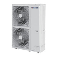
Gree GMV5 Series Owner's Manual (80 pages)
R410A Systems Outdoor Unit
Brand:
Gree
| Category:
Air Conditioner
| Size: 3 MB
Table of Contents
English
5
Table of Contents
5
Safety Instruction
6
General Introduction
8
Outdoor Unit and Indoor Unit Combination
8
Operating Range
8
Before Installation
9
Standard Accessories
9
Installation Location
9
Installation Instruction
11
Physical Dimension of the Outdoor Unit and Mounting Hole
11
Piping Design
14
Oil Return Trap Installation
17
Installation of the Connection Pipe
18
Pressure Check, Vacuum and Additional Refrigerant Charge
22
Electric Wiring
24
Communication Wiring
27
Check Items after Installation and Trial Run
30
Check Items after Installation
30
Trial Run
30
Common Malfunction and Troubleshooting
32
Check before Contacting Service Center
32
Normal Phenomenon
33
Error Display
33
Maintenance
36
Outdoor Heat Exchanger
36
Drain Pipe
36
Check before the Seasonal Use
36
Parts Replacement
37
Maintenance after the Seasonal Use
37
After-Sales Service
38
Français
45
Précautions de Sécurité
46
Combinaison D'unités Extérieures et Intérieures
48
Introduction Générale
48
Plage de Fonctionnement
48
Accessoires Standards
49
Avant la Pose
49
Emplacement de Pose
49
Dimensions Physiques de L'unité Extérieure et du Trou de Montage
51
Instructions de Pose
51
Conception de la Tuyauterie
54
Pose du Déshuileur de Retour
57
Contrôle de Pression, Vide et Charge de Réfrigérant Supplémentaire
62
Câblage Électrique
64
Câblage de Communication
67
Test de Fonctionnement
70
Éléments de Contrôle après la Pose
70
Éléments de Contrôle après la Pose et le Test de Fonctionnement
70
Dysfonctionnements Communs et Dépannage
72
Inspection Préalable à une Demande D'assistance
72
Affichage Des Erreurs
73
Phénomènes Normaux
73
Inspection Avant Utilisation Saisonnière
76
Tuyau D'évacuation
76
Échangeur de Chaleur Extérieur
76
Entretien après Utilisation Saisonnière
77
Remplacement de Pièces
77
Service Après-Vente
78
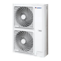
Gree GMV5 Series Owner's Manual (40 pages)
R410A Systems-Outdoor Unit
Brand:
Gree
| Category:
Air Conditioner
| Size: 1 MB
Table of Contents
Table of Contents
5
1 Safety Instruction
6
2 General Introduction
8
Outdoor Unit and Indoor Unit Combination
8
Operating Range
8
3 Before Installation
9
Standard Accessories
9
Installation Location
9
4 Installation Instruction
11
Physical Dimension of the Outdoor Unit and Mounting Hole
11
Piping Design
14
Oil Return Trap Installation
17
Installation of the Connection Pipe
18
Pressure Check, Vacuum and Additional Refrigerant Charge
22
Electric Wiring
24
Communication Wiring
27
5 Check Items after Installation and Trial Run
30
Check Items after Installation
30
Trial Run
30
6 Common Malfunction and Troubleshooting
32
Check before Contacting Service Center
32
Normal Phenomenon
33
Error Display
33
7 Maintenance
36
Outdoor Heat Exchanger
36
Drain Pipe
36
Check before the Seasonal Use
36
Maintenance after the Seasonal Use
36
Parts Replacement
37
8 After-Sales Service
38
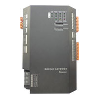
Gree GMV5 Series Technical & Service Manual (20 pages)
Brand:
Gree
| Category:
Gateway
| Size: 1 MB
Table of Contents
Table of Contents
3
Part I Installation
4
System Overview
4
Assembly Introduction
5
Assembly List
5
Safety Requirement for Engineering Installation Construction
5
Gateway Me30-24/D4(B)
5
Function Introduction
5
Appearance Picture
6
Assembly
6
Interface
7
Equipment Installation
8
Product Size and Spatial Size for Electric Control Cabinet Installation
8
Product Size
8
Spatial Size for Electric Control Cabinet Installation
8
Communication Connection
9
Material Selection for Communication Line
9
Communication Connection Method
9
Communication Connection Step
10
Part II Debug Operation
12
Hardware Debug
12
Dial-Up Setting
12
Led Display
13
DI/Do
14
Communication Debug
15
Communication Debug with Air Conditioning Equipment
15
Bacnet GATEWAY CONFIGURATION
16
Communication Debug with Bms System Equipment
16
Exception Handling
17
Part III Maintenance
19
Common Troubleshooting of Bms System
19
Gree GMV5 Series Service Manual (27 pages)
Intelligent Remote System
Brand:
Gree
| Category:
Remote Control
| Size: 5 MB
Table of Contents
Table of Contents
4
Summary
5
Components
5
Network Topological Diagram
5
Details of Gree Intelligent Remote System
5
Controller
7
Router
11
Intelligent Remote Eudemon
11
Product Installation
12
Controller Dimensions and Installation Dimensions for Electric Control Cabinet
12
Installation and Configuration of Router
13
Installation of Intelligent Remote Eudemon
14
Communication Connection
14
Communication Connection Configuration
16
Product Debugging Instruction
17
Debugging of Air Conditioner
17
Debugging of Controller
18
Debugging of Software
21
System
22
Appendix B: TCP/IP Setting
23
Advertisement
Related Products
Gree GMV-504WM/G-X
Gree GMV-560WM/G-X
Gree GMV-504WM/H-X
Gree GMV-560WM/H-X
Gree GMV-1910WM/G-X
Gree GMV-950WM/G-X
Gree GMV-1455WM/H-X
Gree GMV-Pdhm1065W2/Na-M
Gree GMV-Pdhm1460W2/Na-M
Gree GMV-Pdhm1515W2/Na-M
GREE Categories
Air Conditioner
Heat Pump
Dehumidifier
Controller
Air Handlers
More GREE Manuals
Login
Sign In
OR
Sign in with Facebook
Sign in with Google
Upload manual
Upload from disk
Upload from URL