
Subscribe to Our Youtube Channel
Related Manuals for UIrobot UIM241 Series


Summary of Contents for UIrobot UIM241 Series
- Page 1 User Manual UIM241XX Series RS232 Instruction Control Miniature Integrated Stepper Motor Controller (Closed-loop) V1.2...
- Page 2 2. UIROBOT will only work with the customer who respects the Intellectual Property (IP) protection. 3. Attempts to break UIROBOT’s IP protection feature may be a violation of the local Copyright Acts. If such acts lead to unauthorized access to UIROBOT’s IP work, UIROBOT has a right to sue for relief under that Act.
- Page 3 UIM241 Miniature Integrated Stepper Motor Controller( Closed-loop × √ √* × √ √* *: Custom-made, please contact with salesmans before purchase. Examples: UIM241L02P; UIM241C04T-MS; UIM241C08P-IE; Examples of Control Connector options: Screw Terminal Rectangular Plug / Socket UI Robot Technology Co. Ltd. M4120170509EN Page 3...
-
Page 4: General Description
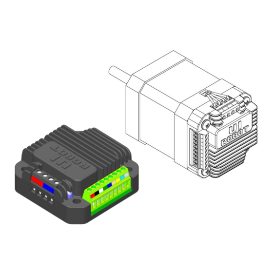
UIM24102/04/08-IE UIM24102 / 04 / 08 RS232 Instruction Control Miniature Integrated Stepper Motor Contrller Miniature Integral Design Embedded DSP Microprocessor Miniature size 42.3mm*42.3mm*16.5mm Firmware DSP, 64bits calculating precision Fit onto motors seamlessly Absolute position record / feedback, reset by instruction or sensor ... -
Page 5: Terminal Description
UIM241 Miniature Integrated Stepper Motor Controller( Closed-loop TERMINAL DESCRIPTION Figure0-1: Terminal Description Motor Terminals Control Termianals Control Terminals Terminal Designator Description Supply voltage, 12 - 48VDC Supply voltage ground To the RX pin on user device To the TX pin on user device To signal ground on user device Analog ground for sensors Sensor input port 1... - Page 6 UIM24102/04/08-IE Attention: If no special instructions, users use UIROBOT controllers must strictly follow the specification that one controller can only drive one motor. Be careful to avoid connecting more than one motor to the controller. The user should be responsible for the loss caused by that error operation, our company will be not responsible for it.
-
Page 7: Typical Application
UIM241 Miniature Integrated Stepper Motor Controller( Closed-loop TYPICAL APPLICATION Wiring of UIM241 is simple. UIM241xx controllers use 3-wire RS232 interface to communicate with user devices. Terminal 3 should be connected to the RX of user device; Terminal 4 should be connected to the TX of user device;... -
Page 8: Instruction Set Summary
UIM24102/04/08-IE INSTRUCTION SET SUMMARY Network Communication Feedback Message Instruction Description Page Header BDR; Set RS232 communication baud rate Model Check Feedback Message Instruction Description Page Header MDL; Check the model of controller Function Configuration Feedback Message Instruction Description Page Header Set enable time, boot time after ... - Page 9 UIM241 Miniature Integrated Stepper Motor Controller( Closed-loop Motion Control Feedback Message Instruction Description Page Header BLC; Set backlash compensation value η BLC; Check backlash compensation value Set acceleration rate MAC; MAC; Check acceleration rate Set deceleration rate MDE; MDE;...
-
Page 10: Characteristics
UIM24102/04/08-IE CHARACTERISTICS Absolute Maximum Ratings Supply voltage......................... 10V to 40V Voltage on S1/S2 with respect to GND..............-0.3V to +5.3V Maximum output current sunk by S1/S2...................20 mA Maximum output current sourced by S1/S2................20 mA Voltage on RX with respect to GND..................-25V to +25V Voltage on TX with respect to GND................ -
Page 11: Table Of Contents
UIM241 Miniature Integrated Stepper Motor Controller( Closed-loop CONTENTS General Description ........................4 Terminal DESCRIPTION ......................5 Typical Application........................7 Instruction set summary ......................8 Characteristics .......................... 10 Overview ........................14 Basic Control System ....................14 Advanced Motion Control Module ................15 Sensor Input Control Module.................. - Page 12 UIM24102/04/08-IE 7.10 Instruction List ......................37 Sensor Input Control ....................39 Rising and Falling Edge ....................40 Analog Input and Thresholds ..................40 Digital Input Sampling Mode ..................41 Sensor Event, Action and Binding ................41 Introduction to Sensor Input Control Instructions ............42 Sensor Input Control Register S12CON ..............
- Page 13 UIM241 Miniature Integrated Stepper Motor Controller( Closed-loop QECη Set desired quadrature encoder’s position............82 QEC Check current encoder position ................83 QERη Set Quadrature Encoder Resolution ..............84 QER Check quadrature encoder resolution ..............85 SCFη / SCFxη Set Sensor Configuration ..............86 SCF Check the value of Sensor Configuration ............
-
Page 14: Overview
UIM24102/04/08-IE 1.0 OVERVIEW UIM241 miniature integrated stepper motor controllers communicate with user device using RS232 protocol. The user device controls UIM241 through ASCII coded instructions. Communication baud rate can be changed through instruction UIM241 has a size of 42.3mm*42.3mm*16.5mm and is designed to mount onto NEMA17/23/34/42 stepper motors seamlessly. -
Page 15: Advanced Motion Control Module
UIM241 Miniature Integrated Stepper Motor Controller( Closed-loop Furthermore, with the encoder-based closed-loop control module, the UIM241 can perform self closed-loop control. Furthermore, with the encoder-based closed-loop control module, the UIM241 can perform self closed-loop control. Real-time Change Notification (RTCN) Similar to CPU’s interrupters, UIM241XX can automatically generate certain messages after predefined events and sends them to the user device. -
Page 16: Encoder-Based Closed-Loop Control Module
In case that a wrong instruction is entered, the controller will return an ACK of error message. Incorrect instructions will not be executed to prevent accidents. UIROBOT provides free Microsoft Windows based VB / VC demo software and corresponding source code to facilitate the quick start of user device side programming. -
Page 17: Instruction And Feedback Structure
UIM241 Miniature Integrated Stepper Motor Controller( Closed-loop 2.0 INSTRUCTION AND FEEDBACK STRUCTURE Once UIM241XX receives a message (instructions) from the user device, it will first ACK back (repeat) the received instruction, and then execute the instruction. UIM241XX will further send back a message to inform the user device of the completion of the instruction. Before a new instruction is received, UIM241XX will keep current working status (e.g. - Page 18 UIM24102/04/08-IE The above instruction set will cause 4 ACK messages being transferred on the RS232 bus. To facilitate the above situation, user can use the following method to send a set of instructions: {Instruction 1; Instruction 2; …Instruction N; }; (N<10) For example: {CUR 20;...
-
Page 19: Rs232 Communication
UIM241 Miniature Integrated Stepper Motor Controller( Closed-loop 3.0 RS232 COMMUNICATION UIM241xx controllers communicate and exchange information with user devices throughRS232 serial protocol. The RS232 configuration of user device, the hand-shaking methods and the instruction used to change the baud rate will be introduced in this Chapter, along with the method to reset the baud rate to factory default. -
Page 20: Instruction List
UIM24102/04/08-IE In 10 seconds, short the terminal 9 (figure 0-1) to analog ground (terminal 6) for 2 times, with intervals around 1 second. Each time, the LED on the controller will flash. If exceed 10 seconds, please restart from step 1. If successful, the LED will turn off for one second and re-lit. -
Page 21: Real-Time Change Notification
UIM241 Miniature Integrated Stepper Motor Controller( Closed-loop 4.0 REAL-TIME CHANGE NOTIFICATION UIM241 controllers support Real-time Change Notification (RTCN). Similar to interrupter of CPU, a RTCN is generated and sent when a user predefined event happens. The length of a RTCN is 4 bytes. The time from the occurrence of the event to the sending of the RTCN is less than 1 millisecond. -
Page 22: Initial And Hardware/Firmware Configuration
UIM24102/04/08-IE 5.0 INITIAL AND HARDWARE/FIRMWARE CONFIGURATION UIM241’s hardware and firmware can be configured through user instructions. There are 4 configuration registers for UIM241: Initial Configuration Register, Master Configuration Register, S12CON and Analog Threshold Register. In this chapter, only the Initial Configuration Register and Mater Configuration Register are described. -
Page 23: Auto-Enable
UIM241 Miniature Integrated Stepper Motor Controller( Closed-loop 5.2 Auto-enable Once ICFG.ENA is set to 1, UIM241 will auto enable the H-Bridge of motor after the power is on for T ms, the interval time (T) can be set through instruction. For details of the instruction, please refer to Chapter 9. -
Page 24: Instruction List
UIM24102/04/08-IE 0 = Disable the Origin (zero) position RTCN. 1 = Enable the Origin (zero) position RTCN. Once the value of pulsing counter or encoder counter is zero, a message will be send to user device automatically. Bit4 STPIE Displacement Control (STP/POS/QEC) Completion RTCN 0 = Disable the displacement control completion RTCN. -
Page 25: Basic Control Instructions
UIM241 Miniature Integrated Stepper Motor Controller( Closed-loop 6.0 BASIC CONTROL INSTRUCTIONS UIM241 controllers support abundant motion control instructions. The instructions of UIm241 are valid for both basic motion control (without acceleration/deceleration or S- curve displacement control) and advanced motion control (if the module is installed and enabled). - Page 26 UIM24102/04/08-IE As shown in Figure 6-2, UIM241 controller operates in PT mode automatically on receiving position instruction such as STP 或者 QEC until an instruction of “STP 0;” is given.(STP is a displacement control instruction. Logically “STP 0;” means no displacement. It is contradictory to send a displacement instruction of no displacement.
- Page 27 UIM241 Miniature Integrated Stepper Motor Controller( Closed-loop Figure6-2 Position Tracking Mode (without acceleration/deceleration) Position 2000 1000 T(Time) -2000 Actual Motor Speed 2000 1000 T(Time) -1000 Operation or Control Desired Current Desired Motor Motor Position Error Event Mode Position Position Speed Direction Speed Stored...
-
Page 28: Basic Instruction Acknowledgment (Ack)
UIM24102/04/08-IE Figure6-3 Shifting between Motion Control Modes Power up offline Instruction OFF; 1) H-bridge disabled, logic circuit working accept, buffer operate instructions PT Mode Instruction ENA; 1) set the desired speed, and then set the desired VT Mode Instruction STP 0; position displacement) successively... -
Page 29: Motor Status Feedback Message
UIM241 Miniature Integrated Stepper Motor Controller( Closed-loop AA denotes a basic ACK message, is a kind of reply to instructions received. ASM (Assembled byte) structure: value N/A(=0) ENA / OFF MCS – 1(0=full step,15=1/16 step) CUR (desired phase current) structure: value N/A(=0) Phase Current (e.g. -
Page 30: Instruction List
UIM24102/04/08-IE 6.4 Instruction List The following table shows the instructions mentioned in this chapter, the detail of those instructions is descriped at the end of the document. Instruction Description Page ACR; Set auto-current attenuation ratio η ACR; Check auto-current attenuation ratio Set output phase current η... -
Page 31: Advanced Motion Control
UIM241 Miniature Integrated Stepper Motor Controller( Closed-loop 7.0 ADVANCED MOTION CONTROL UIM241XX has an optional Advanced Motion Control Module (sold separately) to perform linear/non-linear acceleration/deceleration and S-curve displacement and position control. User can specify corresponding motion control parameters through instructions. Instructions for the advanced motion control includes all the basic motion instructions and 6 additional instructions. - Page 32 UIM24102/04/08-IE UIM241XX can make NEMA17/23 4000RPM (quad step) in 0.25 seconds. UIM241XX controller has the following non-linear acceleration functions. If the desired speed is higher than a certain value (i.e. the Maximum Starting Speed, defined by instruction), and current motor speed is lower than the Max. Starting Speed, then the motor speed will first step up to the Max Starting Speed and then linearly accelerated according to the acceleration rate.
-
Page 33: Nonlinear Deceleration
UIM241 Miniature Integrated Stepper Motor Controller( Closed-loop 7.4 Nonlinear Deceleration Similar to the nonlinear acceleration control, there are three cases and corresponding control algorithms as listed below. If the desired speed is higher than a certain user preset value (i.e. the Maximum Cessation Speed), UIM241XX will use the Uniform Deceleration Control algorithm. -
Page 34: S-Curve Displacement Control
UIM24102/04/08-IE Note: Setting the Maximum Starting Speed or the Maximum Cessation Speed to 0(zero) will force the controller use Linear Acceleration / Deceleration Control Algorithm. 7.5 S-curve Displacement Control S-curve displacement control essentially is the displacement control under the linear acceleration and deceleration speed control. -
Page 35: Direction Control And Position Counter
UIM241 Miniature Integrated Stepper Motor Controller( Closed-loop Figure7-10: S-curve Relative Displacement Control (case 2) Speed Desired Speed Uniform Uniform Acceleration Deceleration T(Time) All the acceleration/deceleration methods may be applied in the S-curve displacement control, including linear acceleration/deceleration and non-linear acceleration/deceleration which is not described in the above figures though. -
Page 36: Backlash Compensation
UIM24102/04/08-IE Absolute position counter is for recording the absolute position of motor. The actual angular displacement is also relative to micro stepping. The value recorded in absolute position counter will be stored automatically on Power Failure situation and can only be cleared on user instruction or preset sensor event. -
Page 37: Enable/Disable Advanced Motion Control Module (Mcfg)
UIM241 Miniature Integrated Stepper Motor Controller( Closed-loop 3) Set deceleration: MDE; Similar to mACC, the deceleration also has two ways to set as listed below. Value mode If the DM bit of the Master Configuration Register is clear to zero (MCFG<DM>=0), then the value of the instruction will be interpreted as the value of the deceleration rate. - Page 38 UIM24102/04/08-IE MDE; Check deceleration rate Set maximum cessation speed η MMD; MMD; Check maximum cessation speed Set maximum starting speed η MMS; MMS; Check maximum starting speed Page 38 M4120170509EN UI Robot Technology Co. Ltd.
-
Page 39: Sensor Input Control
UIM241 Miniature Integrated Stepper Motor Controller( Closed-loop 8.0 SENSOR INPUT CONTROL UIM241XX Motion Controller has an optional (sold separately) Sensor Control Module which supports two sensor input ports: S1, S2. Port S2 can be configured for digital input (0-5V). Port S1 can be configured for either digital input or analog input. Besides digital input condition circuit, UIM241XX has a 12 bits ADC (analog/digital converter) and a 5V reference voltage. -
Page 40: Rising And Falling Edge
UIM24102/04/08-IE 8.1 Rising and Falling Edge When port S1 and S2 is configured for digital input, if the sensor module detects a voltage change on S1(S2) from 0V to 5V, an Sx rising-edge event will be created, meanwhile S1(S2) is assigned a logic value 1 (i.e. S1=1). If the sensor module detects a change on S1(S2) from 5V to 0V, an S1(S2) falling-edge event will be created, meanwhile S1(S2)=0. -
Page 41: Digital Input Sampling Mode
UIM241 Miniature Integrated Stepper Motor Controller( Closed-loop 8.3 Digital Input Sampling Mode Digital input of UIM241 has three sampling mode: 1) Continuous sampling 2) Intermittent sampling 3) Single sampling Continuous Sampling In continuous sampling mode, UIM241 controllers detect level fluctuation at port S1/S2 uninterruptrdly. -
Page 42: Introduction To Sensor Input Control Instructions
UIM24102/04/08-IE • Reset position and encoder counter (code: 6) • Reset position and encoder counter + Reverse displacement control follow the preset motion parameters (speed, displacement, acceleration) (code: 7) • Reset position and encoder counter + Decelerate at preset deceleration until stop (code: •... -
Page 43: Sensor Input Control Register S12Con
UIM241 Miniature Integrated Stepper Motor Controller( Closed-loop 8.6 Sensor Input Control Register S12CON S12CON(Sensor 1/2 Control)defines the binding relationship between S1 and S2 sensor events and actions, as well as the activation of corresponding RTCNs. It is a 16bits register inside the controller, and can be configured using the instruction SCF. When writing to it user needs to affix a 4bits suffix-code to point to this register. - Page 44 UIM24102/04/08-IE Defination Reserved AL <11:0> 位 15-12 Unimplemented, read as 0. 位 11-0 AL<11:0> Lower limit of analog threshold. Note: ATCONH / ATCONL input range is 0 ~ 4095, with 0 corresponding to 0V and 4095 corresponding to 5V. (4095 is the maximum of a 12bits data). Page 44 M4120170509EN UI Robot Technology Co.
-
Page 45: Instruction List
UIM241 Miniature Integrated Stepper Motor Controller( Closed-loop 8.8 Instruction List The following table shows the instructions mentioned in this chapter, the detail of those instructions is descriped at the end of the document. Instruction Description Page SCF; Set sensor control configuration register η SCF;... -
Page 46: Example Of Atconh, Atconl Configuration
UIM24102/04/08-IE 13. If enable auto-feedback, once the motor touches limit switch, user device will receive a feedback message of falling-edge on port S1/S2. 8.10 Example of ATCONH, ATCONL Configuration Similar to S12CON configuration, user needs to first fill every bit of the ATCONH (ATCONL) according to the information provided in previous sections, and then affixes the suffix code 0011 (0010). - Page 47 UIM241 Miniature Integrated Stepper Motor Controller( Closed-loop UI Robot Technology Co. Ltd. M4120170509EN Page 47...
-
Page 48: Encoder And Closed-Loop Control
Also, for this case, encoder power supply is to be provided by user. For UIROBOT UIM241 controller with internal encoder, the S1 and S2 ports are not occupied and therefore are available for sensors. Whether the encoder is built-in or external, the controlling mode and the instructions are the same. -
Page 49: Instruction List
UIM241 Miniature Integrated Stepper Motor Controller( Closed-loop Enable Closed-loop Control Module The Encoder-based Closed-loop Control Module (hereinafter referred to as Closed-loop Control Module) is enabled by configuring the QEM bit of MCFG (MCFG<11>). When MCFG<QEM>=0, this module is disabled; when MCFG<QEI>=1, it is enabled. Please note, closed-loop control module is a must even if user uses external encoders. -
Page 50: Instruction
UIM24102/04/08-IE 10.0 INSTRUCTION This chapter describes the detail of the instructions mentioned in this document. 10.1 Instruction Structure An instruction is a message sent from the user device to motion controller to command certain operatio. Instructions of UIM241 follow the rules listed below: Length of an instruction (including the ending semicolon “;”) should be within 20 characters Coded with standard 7 bits ASCII code (1-127). - Page 51 UIM241 Miniature Integrated Stepper Motor Controller( Closed-loop AA represents the ACK message, which is a repeat of the received instruction. CC represents the status feedback, which is a description of current working status. EE represents the error message. Controller ID The identification number of current controller in a network (also known as Node ID) For UIM 241, Node ID is always 00.
- Page 52 UIM24102/04/08-IE Figure 10-2: Conversion from five 7bits message data to a 32bits data Page 52 M4120170509EN UI Robot Technology Co. Ltd.
- Page 53 UIM241 Miniature Integrated Stepper Motor Controller( Closed-loop UI Robot Technology Co. Ltd. M4120170509EN Page 53...
-
Page 54: Instruction Description
UIM24102/04/08-IE 10.3 Instruction Description This section describes the detail of the instructions mentioned in this document. (In the alphabetic order) ; Check desired motor status Format: Description: Check desired motor status ACK: AA 00 [ASB] [CUR] [V0] [V1] [V2] [P0] [P1] [P2] [P3] [P4] FF Comment: [ASB] >>... -
Page 55: Acrη Set Auto-Current Reduction Ratio
UIM241 Miniature Integrated Stepper Motor Controller( Closed-loop ACRη Set auto-current reduction ratio Format: ACR; set auto-current reduction ratio Description: = 0,1,…,99. = 0, disable auto-current reduction. Standby-CUR = working current. = 1, in standeby mode, current reduces to 50%. Standby-CUR = working current / 2. -
Page 56: Acr Check Auto-Current Reduction Ratio
UIM24102/04/08-IE Check auto-current reduction ratio Format: ACR; Description: Check auto-current reduction ratio ACK: AA 00 BA [A0] FF Comment: Refer to ACK comment of instruction ACR; Note: Require controller Firmware version being 1232 or higher. Page 56 M4120170509EN UI Robot Technology Co. Ltd. -
Page 57: Bdr Set Rs232 Baud Rate
UIM241 Miniature Integrated Stepper Motor Controller( Closed-loop BDR Set RS232 Baud Rate Format: BDR; Description: Set RS232 Baud Rate = 9600, 19200, 38400, 56000, 100000, 115200, 250000; Other value of baud rate is also available, but it must be integral multiple of 100. -
Page 58: Blcη Backlash Compensation
UIM24102/04/08-IE BLCη Backlash compensation Format: BLCη; Description: Set value of backlash compensation in reciprocating motion η = 0,1,…,65535 (Unsigned integer) Units: pps (open-loop) ACK: AA 00 DE [B0] [B1] [B2] FF Comment: >> Message ID of instruction BLCη; [B0] ~ [B2] >>... -
Page 59: Blc Check Backlash Compensation
UIM241 Miniature Integrated Stepper Motor Controller( Closed-loop Check backlash compensation Format: BLC; Description: Check the value of backlash compensation in reciprocating motion ACK: AA 00 DE [B0] [B1] [B2] FF Comment: Refer to ACK comment of instruction BLC; UI Robot Technology Co. Ltd. M4120170509EN Page 59... -
Page 60: Curη Motor Current Adjusting
UIM24102/04/08-IE CURη Motor Current Adjusting Format: CUR; Set the output phase current to . Description: = 0,1,…,80 (unsigned integer) 0…80 represent 0…8.0 amps. ACK: AA 00 [ASB] [CUR] [V0] [V1] [V2] [P0] [P1] [P2] [P3] [P4] FF Comment: [ASB] >>... -
Page 61: Ena H-Bridge Enable
UIM241 Miniature Integrated Stepper Motor Controller( Closed-loop H-Bridge Enable Format: ENA; Description: Enable the stepper motor driver (i.e. H-bridge driving circuit). ACK: AA 00 [ASB] [CUR] [V0] [V1] [V2] [P0] [P1] [P2] [P3] [P4] FF Comment: [ASB] >> Received data 0 [CUR] >>... -
Page 62: Enaη Set Enable Time
UIM24102/04/08-IE ENAη Set enable time Format: ENA; Description: Set auto-enable time register ENAtimer. Controller auto-enable the H-bridge circuit afer power is on for ms. = 1,2,…,60000; ACK: AA 00 A0 [E0] [E1] [E2] FF Comment: >> Message ID of instruction ENA; [E0] ~ [E2] >>... -
Page 63: Enaxffff Check Enable Time
UIM241 Miniature Integrated Stepper Motor Controller( Closed-loop ENAxFFFF Check enable time Format: ENAxFFFF; Description: Check auto-enable time ACK: AA 00 A0 [E0] [E1] [E2] FF Comment: Refer to ACK comment of instruction ENA;. Note: This instruction checks ENAtimer only, can not enable controller. Require controller Firmware version being 1232 or higher. -
Page 64: Fbk Motor Status Feedback Inquiry
UIM24102/04/08-IE Motor Status Feedback Inquiry Format: FBK; Description: Check the current motor status ACK: AA 00 [ASB] [CUR] [V0] [V1] [V2] [P0] [P1] [P2] [P3] [P4] FF Comment: [ASB] >> Received data 0 [CUR] >> Received data 1 [V0] ~ [P4] >>... -
Page 65: Icfxη Initial Configuration Register Instruction
UIM241 Miniature Integrated Stepper Motor Controller( Closed-loop ICFxη Initial Configuration Register Instruction Format: ICFx; Description: Configure the initial configuration register (InitCFG) Parameter has two bytes, structure is as follow: Byte Defination Where, [D1 D0] compose a hexadecimal 16bit data. D1 is high, D0 is low. Example: Initial Configuration = 0x1234;... -
Page 66: Icf Check Initial Configuration Register
UIM24102/04/08-IE Check Initial Configuration Register Format: ICF; Description: Check initial configuration register ACK: AA 00 DA [C0] [C1] [C2] FF Comment: Refer to ACK comment of ICFx; Note: Require controller Firmware version being 1232 or higher. Page 66 M4120170509EN UI Robot Technology Co. Ltd. -
Page 67: Macη Set Acceleration Rate
UIM241 Miniature Integrated Stepper Motor Controller( Closed-loop MACη Set Acceleration Rate Format: MAC; Set the acceleration rate to . Description: = 1、2 … 65,000,000; (Pre-requiring MCFG<AM> = 0, value mode) = 1、2 … 60,000; (Pre-requiring MCFG<AM> = 1, period mode) ACK: AA 00 B1 [FG] [A0] [A1] [A2] [A3] [A4] FF Comment:... -
Page 68: Mac Check Current Acceleration Rate
UIM24102/04/08-IE Check Current Acceleration Rate Format: MAC; Description: Check current acceleration rate ACK: AA 00 B1 [FG] [A0] [A1] [A2] [A3] [A4] FF Comment: Refer to ACK comment of MAC;. Page 68 M4120170509EN UI Robot Technology Co. Ltd. -
Page 69: Mcfη / Mcfxη Master Configuration Register Instruction
UIM241 Miniature Integrated Stepper Motor Controller( Closed-loop MCFη / MCFxη Master Configuration Register Instruction Format: MCF; or MCFx; Description: Setup Master Configuration Register 1) If is decimal, Use format: MCF; Where, = 0,1,…65535 (16 bits unsigned integer) 2) If is hexadecimal, Use format MCFx;... -
Page 70: Mcf Check Master Configuration Register
UIM24102/04/08-IE Check Master Configuration Register Format: MCF; Description: Check the value of the Master Configuration Register ACK: AA 00 B0 [C0] [C1] [C2] FF Comment: Refer to ACK comment of MCF; Page 70 M4120170509EN UI Robot Technology Co. Ltd. -
Page 71: Mcsη Setup Micro Stepping
UIM241 Miniature Integrated Stepper Motor Controller( Closed-loop MCSη Setup Micro Stepping Format: MCS; Description: Set micro-stepping resolution. = 1,2,4,8,16 (unsigned integer); = 1, 2, 4, 8, 16 represents the full, half, quarter, eighth and sixteenth step resolution, respectively. ACK: AA 00 [ASB] [CUR] [V0] [V1] [V2] [P0] [P1] [P2] [P3] [P4] FF Comment:... -
Page 72: Mdeη Set Deceleration Rate
UIM24102/04/08-IE MDEη Set Deceleration Rate Format: MDE; Set the deceleration rate to . Description: = 1、2 … 65,000,000;(Pre-requiring MCFG<DM> = 0, value mode) = 1、2 … 60,000; (Pre-requiring MCFG<DM> = 1, period mode) ACK: AA 00 B2 [FG] [D0] [D1] [D2] [D3] [D4] FF Comment: >>... -
Page 73: Mde Check Current Deceleration Rate
UIM241 Miniature Integrated Stepper Motor Controller( Closed-loop Check Current Deceleration Rate Format: MDE; Description: Check current deceleration rate ACK: AA 00 B2 [FG] [D0] [D1] [D2] [D3] [D4] FF Comment: Refer to ACK comment of MDE;. UI Robot Technology Co. Ltd. M4120170509EN Page 73... -
Page 74: Mdl Check Controller Model
UIM24102/04/08-IE Check Controller Model Format: MDL; Description: Check the Model, installed optional modules and firmware version of current controller. ACK: CC 00 DE 18 02 [CUR] [asb] [V0] [V1] [V2] FF Note: [ ] denotes one byte, the data is hexadecimal. Comment: >>... -
Page 75: Mmdη Set Maximum Cessation Speed
UIM241 Miniature Integrated Stepper Motor Controller( Closed-loop MMDη Set Maximum Cessation Speed Format: MMD; Set the maximum cessation speed at . Description: = 1、2 … 65,000,000; (unsigned integer) ACK: AA 00 B4 [M0] [M1] [M2] FF COMMENT: >> The message ID of MMD; [M0] ~ [M2] >>... -
Page 76: Mmd Check Current Maximum Cessation Speed
UIM24102/04/08-IE Check current Maximum Cessation Speed Format: MMD; Description: Check the maximum cessation speed ACK: AA 00 B4 [M0] [M1] [M2] FF Comment: Refer to ACK comment of MMD;. Page 76 M4120170509EN UI Robot Technology Co. Ltd. -
Page 77: Mmsη Set Maximum Starting Speed
UIM241 Miniature Integrated Stepper Motor Controller( Closed-loop MMSη Set Maximum Starting Speed Format: MMS; Set the maximum starting speed at . Description: = 1、2 … 65,000,000; (unsigned integer) ACK: AA 00 B3 [M0] [M1] [M2] FF Comment: >> The message ID of MMS; [M0] ~ [M2] >>... -
Page 78: Mms Check Current Maximum Starting Speed
UIM24102/04/08-IE Check current Maximum Starting Speed Format: MMS; Description: Check the maximum starting speed ACK: AA 00 B3 [M0] [M1] [M2] FF Comment: Refer to ACK comment of MMS; Page 78 M4120170509EN UI Robot Technology Co. Ltd. -
Page 79: Off H- Bridge Disable
UIM241 Miniature Integrated Stepper Motor Controller( Closed-loop H- Bridge Disable Format: OFF; Description: Disable the stepper motor driver (i.e. H-bridge driving circuit). ACK: AA 00 [ASB] [CUR] [V0] [V1] [V2] [P0] [P1] [P2] [P3] [P4] FF Comment: [ASB] >> Received data 0 [CUR] >>... -
Page 80: Org Reset Position Counter
UIM24102/04/08-IE Reset Position Counter Format: ORG; Description: Reset the position/encoder counter to zero (0), is equivalent to instruction ORG=0; ACK: AA 00 B7 [P0] [P1] [P2] [P3] [P4] FF Comment: Please refer to “29. POS;”. Page 80 M4120170509EN UI Robot Technology Co. Ltd. -
Page 81: Orgη Reset Position Counter
UIM241 Miniature Integrated Stepper Motor Controller( Closed-loop ORGη Reset Position Counter Format: ORG; Reset the position/encoder counter to a given value . Description: = - 2147483647 ~ + 2147483647 (signed integer) = 0, reset the position/encoder counter to zero (0) ... -
Page 82: Qecη Set Desired Quadrature Encoder's Position
UIM24102/04/08-IE QECη Set desired quadrature encoder’s position Format: QECη; Description: Set desired encoder positon to η. η = - 2,000,000,000…-1, 0, 1 … + 2,000,000,000。 ACK: AA 00 B8 [Q0] [Q1] [Q2] [Q3] [Q4] FF Comment: >> Message ID of desired encoder positon; [Q0] ~ [Q4] >>... -
Page 83: Qec Check Current Encoder Position
UIM241 Miniature Integrated Stepper Motor Controller( Closed-loop Check current encoder position Format: QEC; Description: Check current encoder position ACK: CC 00 B8 [Q0] [Q1] [Q2] [Q3] [Q4] FF Comment: >> Message ID of current encoder position; [Q0] ~ [Q4] >> Received data 0 ~ 4 [Q0] ~ [Q4] is the converted value for current encoder position. -
Page 84: Qerη Set Quadrature Encoder Resolution
UIM24102/04/08-IE QERη Set Quadrature Encoder Resolution Format: QERη; Description: Set the quadrature encoder resolution to η. η = 0, 1 … 65000。 ACK: AA 00 C2 [R0] [R1] [R2] FF Comment: >> Message ID of QER; [R0] ~ [R2] >> Received data 0 ~ 2 [R0] ~ [R2] is the converted value for encoder resolution. -
Page 85: Qer Check Quadrature Encoder Resolution
UIM241 Miniature Integrated Stepper Motor Controller( Closed-loop Check quadrature encoder resolution Format: QER; Description: Check current quadrature encoder resolution ACK: AA 00 C2 [R0] [R1] [R2] FF Comment: Refer to ACK comment of instruction QERη; UI Robot Technology Co. Ltd. M4120170509EN Page 85... -
Page 86: Scfη / Scfxη Set Sensor Configuration
UIM24102/04/08-IE SCFη / SCFxη Set Sensor Configuration Format: SCF; or SCFx; Description: Configure S12CON、ATCONH and ATCONL. 1) When is decimal: Instruction type is SCF; Where, = 0,1 … 1048575 (24 bits unsigned integer) 2) When is hexadecimal: Instruction is SCFx;... -
Page 87: Scf Check The Value Of Sensor Configuration
UIM241 Miniature Integrated Stepper Motor Controller( Closed-loop Check the value of Sensor Configuration Format: SCF; Description: Check the current value of S12CON\ATCONH and ATCONL ACK: AA 00 C0 [S0] [S1] [S2] [AL0] [AL1] [AH0] [AH1] FF Comment: Refer to ACK comment of SCF; UI Robot Technology Co. -
Page 88: Sfb Check Sensor Data
UIM24102/04/08-IE Check Sensor Data Format: SFB; Description: Check sensor readings and status ACK: CC 00 C1 [D1] [D2] [AN0] [AN1] FF Comment: >> The message ID of SFB; [D1] ~ [D2] >> Received data 1 ~ 2 [AN0] ~ [AN1] >> Received data 4 ~ 5 [D1] ~ [D2] represent the logic level of S1, S2 respectively (0/1). -
Page 89: Spdη Speed Adjusting
UIM241 Miniature Integrated Stepper Motor Controller( Closed-loop SPDη Speed Adjusting Format: SPD; Set the desired speed to . Description: = - 65535…-1, 0, 1 … + 65535; (signed integer) ACK: AA 00 B5 [V0] [V1] [V2] FF Comment: >> The message ID for desired speed [V0] ~ [V2] >>... -
Page 90: Spd Check Current Speed
UIM24102/04/08-IE Check Current Speed Format: SPD; Description: Check current speed ACK: CC 00 B2 [V0] [V1] [V2] FF Comment: >> The message ID of current speed [V0] ~ [V2] >> Received data 0 ~ 2 [V0] ~ [V2] is the converted value for the value of desired speed. (16 bits) (Figure 10-1) Unit: Pluse/ Second,PPS or Hz. -
Page 91: Sqtη Set Tolerance Of Blocked Alarm
UIM241 Miniature Integrated Stepper Motor Controller( Closed-loop SQTη Set tolerance of blocked alarm Format: SQTη; Description: Set tolerance of blocked alarm. Alarm when deciation of reading between encoder and pulse counter is larger than η. η= 0, 1 … + 65535。 AA 00 B8 [Q0] [Q1] [Q2] [Q3] [Q4] FF Comment: >>... -
Page 92: Stgxη Set Digital Input Sampling Mode
UIM24102/04/08-IE STGxη Set Digital Input Sampling Mode Format: STGx; Description: Set sampling mode of digital input: continnous, intermittent and single sampling. Structure of : Byte Defination Where, [D1 D0] compose a hexadecimal 16bit data, D1 is high, D0 is low. IDX = 00,01 (hexadecimal) denotes configurating sensor 1,2;... -
Page 93: Stg Check Digital Input Sampling Mode
UIM241 Miniature Integrated Stepper Motor Controller( Closed-loop Check Digital Input Sampling Mode Format: STG; Description: Check digital input sampling mode of S1, S2 ACK: AA 00 C9 [S0] [S1] [S2] [S3] [S4] [S5] FF Comment: Refer to ACK comment of instruction STGx; UI Robot Technology Co. -
Page 94: Sto Eeprom Store
UIM24102/04/08-IE EEPROM Store Format: STO; Description: Banding motion parameters to motions (Triggered by sensor edge or controllered by instruction) Motion parameters include: 1) Acceleration 2) Deceleration 3) Max. starting speed 4) Max. cessation speed For sensor, there also has: 5) Speed 6)... -
Page 95: Stoη Parameter Banding
UIM241 Miniature Integrated Stepper Motor Controller( Closed-loop STOη Parameter Banding Format: STO; Description: Banding motion parameters to motions (Triggered by sensor edge or controllered by instruction) = 0,1,…,5 = 0, >> Montion controlled by instrcution = 1, >> Only for close-loop ... -
Page 96: Stpη Displacement Control
UIM24102/04/08-IE STPη Displacement Control Format: STP; Description: Set the desired incremental displacement, i.e. the displacement relative to current position = - 2,000,000,000…-1, 0, 1 … + 2,000,000,000; (signed integer) ACK: AA 00 B6 [P0] [P1] [P2] [P3] [P4] FF Comment: >>... -
Page 97: Stp Check Displacement
UIM241 Miniature Integrated Stepper Motor Controller( Closed-loop Check Displacement Format: STP; Description: Check current incremental displacement. ACK: CC 00 B3 [P0] [P1] [P2] [P3] [P4] FF Comment: >> The message ID of current incremental displacement [P0] ~ [P4] >> Received data 0 ~ 4 [P0] ~ [P4] is the converted value for the current incremental displacement (32 bits) (Figure 10-2) UI Robot Technology Co. - Page 98 UIM24102/04/08-IE APPENDIX A DIMENSIONS Units: mm Page 98 M4120170509EN UI Robot Technology Co. Ltd.
- Page 99 UIM241 Miniature Integrated Stepper Motor Controller( Closed-loop APPENDIX B INSTALLATION INSTRUCTION NEMA 17 (do not need flange) Fix the UIM controller on motor with screw (2 or 4) Connect the motor pin to motor terminal of UIM controller NEMA 23/34/42 (need flange) Fix flange on motor Fix the UIM controller on flange with screw Connect the motor pin to motor terminal of UIM controller...
Need help?
Do you have a question about the UIM241 Series and is the answer not in the manual?
Questions and answers